Do-it-yourself homemade outer CV joint puller: drawings, dimensions, photos and videos of homemade work in action.
The craftsman Andrei Mashkov made with his own hands - a device, a puller for CV joints. The design itself is simple and fully functional.
The figure shows drawings of a device for removing CV joints.
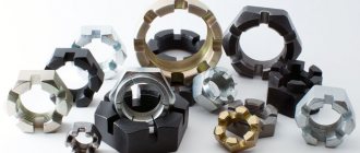
The photo shows the design of the puller; it is made of two blanks with a wall thickness of 10 mm and welded to a nut with an outer diameter of 46 mm and an inner diameter of 30 mm. Two fastening plates were also made, two nuts were welded into one of them.
Using the device is quite simple; we fasten the plates with bolts.
We also fix the device itself between the plates with bolts.
We unscrew it with a wrench and remove the CV joint from the splines.
In this video, the author shows in detail his homemade product in action.
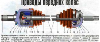
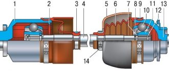
Types of CV joints, their design and operating principle
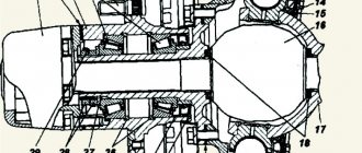
CV joint device: 1. Right front wheel drive;
2. Gearbox; 3. Left front wheel drive; 4. External joint housing; 5. Retaining ring of the hinge cage; 6. 18. Hinge cage; 7. 19. Hinge separator; 8. 17. Hinge ball; 9. Outer clamp of the cover; 10. 15. Protective cover for the hinge; 11. Thrust ring; 12. 14. Left wheel drive shaft; 13. Inner clamp of the cover; 14. Internal hinge lock; 15. 20. Retaining ring of the inner joint cage; 16. 21. Shaft buffer; 17. 22. Internal hinge housing; 18. 23. Axle gear retaining ring. There are several types of CV joints, but only two are widespread in passenger cars:
The design of a ball CV joint includes two cages - an internal one, in the form of a spherical fist (fitted onto the shaft), and an external one (made integral with the shaft end, which is inserted into the hub or gearbox). Between them there are balls placed in special grooves, which are kept from falling out of the hinge by a separator. It is the balls and the grooves along which they move that are the main working elements of the CV joint, since they transmit rotation and allow you to change the angle of one race relative to the other.
To prevent the inner race from coming off the shaft, it is secured with a retaining spring ring located in a special groove on the shaft. The locking ring is also used on the shaft ends of the outer race of the internal joint.
The tripoid joint does not have an internal race; instead, a three-pin fork mounted on the shaft is used. Each cleat on this fork has spherical rollers on needle bearings. Thanks to these rollers, rotation is transmitted, the shaft with the fork can change the angle relative to the cage, and also move longitudinally relative to the outer cage (enter into it), which makes it possible to change the length of the drive.
The connection between the fork and the shaft is splined, but at the same time it fits onto the shaft quite tightly. Additionally, the fork is secured with a retaining ring to prevent it from jumping off.
It is noteworthy that tripoidal CV joints are used only on the gearbox side, but they are not used on the hub side.
Ball joints can be located on both sides. That is, you can find drive shafts on cars with two ball joints, internal tripoid joints and external ball joints, but never with two tripoid CV joints. This is due to the peculiarities of the operation of each of these types of hinges.
It is interesting that some cars (for example, Volkswagen Golf 2) use an internal ball joint of an interesting design - the outer race with the shaft end is not made at the same time, but they are connected to each other by bolts. We'll touch on them a little later.
Drive Features
Making a car with driving front wheels allows constant velocity joints (CV joints), which are used in the drive design. The peculiarity of this type of hinge is the ability to transmit torque without loss when rotating one component of the drive relative to another at an angle of up to 70 degrees.
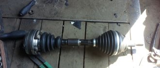
Car front wheel drive shaft
The drive shaft of a vehicle with a front drive axle must perform several functions, and simultaneously. It must transmit torque to the wheel hub from the gearbox, provide the ability for the wheel to move relative to the body (when driving over uneven surfaces), and also allow changing the angle of the wheel, that is, making turns (which is accompanied by the need to change the length of the shaft). And all this is done thanks to constant velocity joints.
In general, the design of the drive shaft of a front-wheel drive car consists of three elements:
- shaft (with splines at the ends for connection with hinges);
- internal CV joint (which connects the drive to the gearbox);
- external CV joint (for connection to the wheel hub).
There are two such drive shafts in a front-wheel drive car, one for each drive wheel.
Replacing the inner CV joint with your own hands
Oil filter puller: factory and home-made varieties
» alt=»»> The procedure for replacing the “grenade” is the same for the entire front-wheel drive VAZ line, starting with 2108 and ending with the VAZ-2115, “Kalina”, “Priora”, “Granta”. Before removing the inner CV joint, the oil is drained from the gearbox. Then proceed according to the following algorithm:
- Unlock and unscrew the hub nut. To make the work easier, a piece of pipe about 1 meter long should be put on the key.
- The desired side of the car is hung on a jack or lift.
- Remove the wheel.
- Remove the washer located under the hub nut installation site.
- Disconnect the steering tip.
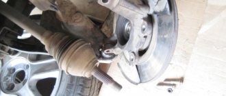
- The CV joint is removed from the hub.
- Using a pry bar, remove the drive and internal joint from the gearbox.
How to change the “grenade” with the drive removed? To do this, clamp the shaft in a vice, loosen the clamps and remove the boot. After this, the hinge is knocked off the splines with hammer blows.
CV joint puller: principle of operation and its necessity
Replacing the CV joint boot: how to change the boot yourself
It happens that it is necessary to replace not the entire CV joint, but its front part or the outer boot. In this case, the rationale for completely dismantling the “grenade” drive is called into question. Most experienced motorists in such situations choose partial disassembly of the CV joint, that is, removal of its outer part. Sometimes such an event is quite difficult to carry out without special devices - pullers, which greatly facilitate the process, making it less labor-intensive and chaotic.
The CV joint puller is a squeezing and pulling mechanism. With the help of some bolts, the device is fixed on the open part of the shaft, and with the help of others, the inside of the grenade is pushed out. For a clearer understanding of the operating principle of the puller, study the image below.
A few movements with a wrench when using a removable CV joint device help, as they say, to kill several birds with one stone:
- reduce the risk of breakage of the “grenade” and its surrounding elements to zero, which can happen when using handicraft repair methods (hammer, pry bar, etc.);
- facilitate the repair process;
- do the procedure without getting particularly dirty;
- carry out replacement quickly and efficiently.
As you can see, a device for removing constant velocity joints is very effective for partial repair of a part (replacing the outer part or boot, for example). Purchased accessories
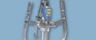
It is worth noting that in addition to pullers for the outer part of the CV joint, there are similar devices for the internal “grenade” and universal ones (suitable for both repair options). If for the first case it is quite possible to make the device yourself, then for removing the internal hinge it is very difficult. In this case, it is easier to resort to buying a ready-made device from a car store.
To be fair, we note that there will definitely be no problems in this aspect. Almost every auto shop has CV joint pullers in its assortment. The price category of these products varies widely, since the cost of the device depends on the quality of the metals used and its reliability. Moreover, if you wish, you can find not only a puller for removing the CV joint (its various parts), but also a puller for CV joint clamps, which is sometimes simply necessary during repairs.
When choosing and purchasing a removable device for grenades, you should follow simple recommendations:
- By first studying reviews about certain pullers or manufacturers on the Internet, you can quickly and without risks make the right choice.
- Do not buy the cheapest devices (100-300 rubles), as they are often made of low-quality metals and are “disposable”. Often such pullers break during the repair process.
- However, you shouldn’t take too expensive devices, because in most cases the markup is for the brand (excluding multifunctional universal pullers).
By following the tips above, you are guaranteed not to make a mistake and make the right choice.
puller for outer CV joints without dismantling.
Replacement of outer CV joint for Ford Focus 2
Now I'll know what he's for)))
I took this one a long time ago. I’ve never used ska before))) ska in Fig. 7
Now I'll know what he's for)))
100 rubles maybe even less
why buy it? there are enough drills and monkeys to do it.
It is often faster to buy if it costs little than to waste time searching for pieces of iron and processing them. and yes, everything is primitive.
Googled it. This is the type of design that is commonly found.
what's the point there? that it is necessary to push it out of the shaft using the inner race. (if you change the boot) because with the puller that you dug, the load will be on the balls and working surfaces of the CV joint. but this half of the puller will leave a half ring (6), and sharpen the part at the bottom in your photo for the wedge.
Hello everyone interested in the topic. The tuning studio “From Matches and Acorns” is with you, and today I will tell you how I made an external CV joint puller from junk, for free, without SMS and registration. Perhaps my experience will be useful to someone and give them some ideas.
In the process of a large-scale repair of the basin, I needed to bring the drive shafts into decent shape, namely, perform a full range of maintenance work: assess the wear of the hinges and their suitability for further use, replace cracked boots, lubricant, clean everything and paint. For all these operations, the hinges must be removed from the shafts. And this is where things get interesting. You can use a sledgehammer to knock it down through the extension the old fashioned way; you can use various types of pullers. Due to the fact that there are no assistants or a powerful workbench with yews available, the first method disappeared by itself. Three of the four hinges were removed normally using a traditional and simple expanding puller made of two split rings, but the fourth decided to put up desperate resistance. The clamping force of the stop on the shaft was not enough - instead of a clip, as it should have been, the force moved the stop along the shaft. Twice I tore off the clamping bolts, even the protrusion under the boot did not stop it - instead of resting against it, the puller crawled onto it, crushing the stronger bolts and pulling the threads already in the piece of iron. After organizing a more reliable stop, the threads of the spacer bolts eventually broke due to wild force. The CV joint remained unshaken and seemed to grin.
There are universal outer CV joint pullers on sale that tighten the joint with its own nut or bolt. This design and principle of operation formed the basis of the homemade product, and with the money saved you can buy more spare parts.
Reverse hammer for body repair: step-by-step instructions
The process of manufacturing a reverse hammer begins with the preparation of the material. A metal rod 12 mm thick and 50 centimeters long will be used as a handle.
1. Making a movable “weight”
The weight for the reverse hammer is made of a rod with a diameter of 16 mm. The rod is cut into 5 even pieces, the length of which is 12-16 centimeters. The rods are secured to the main handle using electrical tape, and then they are welded together using a longitudinal welding seam. It is important to consider the absence of weld slag on the surface of the handle.
2. Tapping the top of the recoil hammer handle
The thread is cut for a long nut about 2-3 centimeters along the rod. This procedure should be carried out taking into account all angles, as this determines how strong the reverse straightening hammer will be.
3. Making bent hooks for a reverse hammer
These hooks are necessary for aligning parts in different planes. The production of elements is carried out individually depending on the needs of the user. The bending procedure is carried out using a sledgehammer and a stop.
4. Threading metal hooks
The threads are also cut on the finished hooks for the reverse hammer in order to use a long nut to connect the two elements necessary for the operation of this tool. The cutting must occur at an even angle so that the two connected parts are without distortions, otherwise the hook may break off the thread during the working process.
5. Installing lock washers on the handle
To obtain a high-quality universal return hammer, it is necessary to make reliable lock washers. These elements take most of the load during impacts, so their installation must be carried out taking into account all angles. A thread is cut at the end of the handle onto which a nut and washer are then screwed. Before installing the washer, a rubber handle made of electrical tape or rubber hose is mounted.
6. Checking the functionality of the reverse hammer assembly
The completed return hammer should work without jamming or any difficulties. All mechanisms move smoothly.
Features of replacing a tripod CV joint
Finally, let’s look at how the internal tripod joint of angular velocity changes using the example of the Ford Focus 2. The tools you will need are the same as those indicated above, as well as a universal three-legged puller and pliers for removing the retaining rings.
The difficulty of replacement is that you will have to completely remove the drive shaft. Everything is done like this:
- We take out the external hinge from the hub (identical to the VAZ-2110).
- We climb under the car, cut off the large clamp of the inner CV joint, and tighten the boot.
- We remove the shaft (there remains an assembled outer joint on one side and a three-pin fork on the other, while the outer race remains in the gearbox).
- We remove the outer race (push out the limit switch using a pry bar driven between the race and the gearbox);
- Using pliers, remove the retaining ring holding the fork.
- We pull the fork itself from the shaft with a puller.
- We place the boot and the new element on the shaft and install the retaining ring back.
- We put the outer ring in place (you can carefully hammer it in with a hammer with an adapter).
- Install the drive shaft.
- Apply grease, pull the boot onto the outer race and secure it with clamps.
- We collect everything removed in reverse order.
As you can see, there is no particular difficulty in replacing CV joints, and all work can be done independently in a garage.
Varieties
Despite the fact that the design of the reverse hammer is quite simple, over time even it has had several modifications. This or that option is used in different cases - it all depends on the skill, as well as the type of deformation. But in general, the design is always the same, the operating principle is the same. The differences lie only in the method of attaching such a tool to the body.
The simplest version of the hammer:
- This is a metal rod, at one end of which there is a hook, and at the other - a load and a stop;
- A hook is attached to the washer, and the washer is welded to the place of deformation by welding;
- Provided impact forces are applied to the load, the deformation is extended to the desired moment.
But the second option (also quite simple) will differ somewhat from the first. At the end, instead of a hook, there is a simple thread. In order to level the surface using such a device, a hole is made in the center of the deformation, into which the threaded end is inserted, and a nut and washer are attached to it on the reverse side.
A vacuum hammer is the most complex version of its implementation. It is attached to the surface of the deformed area using rarefied air. The suction cup begins to work both in the usual way and with the help of a compressor.
Thanks to the vacuum device, minor body damage can be repaired and the paintwork can be preserved intact.
The CV joint is crunching - how to determine which one, and what to do?
Hello, dear motorists! A car enthusiast can only consider himself a real car owner when he is truly concerned about the condition of the car’s components and assemblies, and every new knock, creaking and other signs of car breakdowns haunt him.
Driving a car can be called comfortable only if all elements are in good working order.
However, each part, especially those that operate under load and friction like a CV joint, has its own working life.
Sooner or later, the material wears out and loses its properties, which leads to failure of the part. This is objective. And a “hint” about an impending breakdown from the part itself must be taken seriously. It’s better not to wait for the car to stop on a long journey, but to immediately begin troubleshooting and fixing it.
Owners of front-wheel drive cars are familiar with such an unpleasant phenomenon as a CV joint crunching. Considering that the front suspension of the car, in addition to its main functions, must also ensure the transmission of rotation from the differential gears to the drive wheels, it is equipped with unique devices: constant velocity joints, which in its abbreviated version sounds like “CV joint”.
This part is very important and quite complex in design; therefore, it is expensive and requires increased attention. If the CV joint crunches, then without any hesitation you need to take the car in for repairs and change it.
Why does the CV joint crunch?
Video of replacing the outer left CV joint
Experienced drivers are able to determine the location of a car breakdown by ear. Such skills are acquired over time, but the crunch of a CV joint cannot be confused with anything.
In order to understand the nature of this characteristic noise, you should remember how the CV joint is designed. The task of the CV joint is the transmission of rotation from one axle shaft to another, provided that the angle between them continuously changes.
This property is due to the need not only to rotate the drive wheel, but also to give it the ability to turn and move up and down on a spring.
The CV joint consists of the following main elements:
- outer body in the form of a bowl with six semicircular grooves inside and a semi-axis outside;
- the inner race is in the form of a spherical fist and also has six grooves and a splined connection for the axle shaft;
- Between the inner walls of the bowl and the holder there are 6 balls in the separator.
All elements are made so precisely that they have no play when assembled. The cage transmits force through the balls to the body and rotates it, and moving the balls along the grooves makes it possible to change the angle between the axle shafts.
Over time, a hole forms at the point where the balls come into contact with other elements and a backlash appears. The free movement of the balls (rolling) generates a sound that is very similar to crunching.
Considering that CV joints are installed two on each wheel, when alarming symptoms appear, it becomes difficult to find out which CV joint is crunching: inner or outer, right or left.
How to determine which CV joint is crunching: external or internal, right or left?
As you know, each drive wheel of a front-wheel drive car has two equal angular velocity joints: the inner one transmits rotation from the differential gears to the axle, and the outer one directly from the axle to the wheel hub. The outer and inner CV joints have the same design, but different sizes. The outer one wears out more intensively and fails faster.
You can determine for yourself which CV joint is crunching in two ways:
- on a stationary car, trying to pull the axle one by one at the hinges. In a working CV joint there should be no play. If it knocks, it means the output is already large enough;
- in motion, performing various maneuvers and listening to the sounds made.
First you should try to diagnose the outer CV joints. To do this, turn the steering wheel as much as possible while moving on a flat surface in one direction, and then in the other.
If the CV joint knocks when turning to the right, then, accordingly, the right one is faulty, and when turning to the left, the left one is faulty.
The wear of the inner CV joint is determined during straight-line movement, but it is necessary to deliberately select an uneven section of the road, where there will be a ditch or hole, so that the wheel drops as low as possible while moving.
By driving the right and left wheels alternately into the recess, you can determine which side of the CV joint requires replacement. And of course, after you diagnose which one is crunching, immediately begin replacing the CV joint.
How to make a CV joint puller yourself
There are a huge number of ways to make removable devices for grenades. Each of them is good and convenient in its own way, but the general principle of their construction is simple. To make most pullers, you will need the help of a turner, who can make the device within half an hour.
To understand how to make a CV joint puller with your own hands, check out the diagrams/images and videos below:
CV joint (constant velocity joint) is a mechanism that allows you to transmit torque between misaligned shafts. The device is actively used on front-wheel drive vehicles. On each shaft coming out of the gearbox there are two of them - internal and external. Repair is impossible; if the unit breaks down, it is replaced as an assembly.
Puller drawings. Repair equipment. Tool
Rear hub and brake disc remover.
Photo of the puller
A device for removing the CV joint from the gearbox.
Made from an old open-end wrench with a welded pipe.
Replacing the CV joint boot.
A vodka cap is suitable, but other suitable containers can be used. The principle is shown in the figure. We apply oil and everything goes completely smoothly.
Drawing of a CV joint puller.
The puller consists of three parts. Moreover, different half rings are needed for the outer and inner CV joints.
A set of mandrels for pressing oil seals into the gearbox.
Drawing of a mandrel for installing oil seals.
Device for grinding valves.
Device for grinding valves.
A device for grinding valves using an electric drill.
The device for grinding valves using a drill is a crank mechanism.
The procedure for assembling the device and the nature of the connection of its parts are given below.
The rotational motion from the electric drill is transmitted to the roller 1, disk 11 with the crank (pin) 12 and is converted into the rocking movement of the slide 4, which, in turn, is converted into the required rocking movement of the lever 9.
Lever 9 is connected to roller 7, which ensures the lapping movement. The connection of the roller 7 with the valve is carried out using a suction cup.
Valve grinding occurs as follows. We hold the drill with one hand, and with the other we hold on to body 5. There is no need to press the valve, the weight of the drill is enough. During operation, we gradually turn the device, moving the grinding zone. An external sign of the end of lapping is the receipt of an even, continuous matte or shiny strip 1.2 mm wide on the working surfaces of the valve and its seat.
After grinding in, thoroughly wash the valves and seats so that the paste does not get on the working surfaces of the valve stem and bushing, otherwise intensive wear of the latter will occur.
How to make a CV joint puller yourself
There are a huge number of ways to make removable devices for grenades. Each of them is good and convenient in its own way, but the general principle of their construction is simple. To make most pullers, you will need the help of a turner, who can make the device within half an hour.
To understand how to make a CV joint puller with your own hands, check out the diagrams/images and videos below:
https://youtube.com/watch?v=JwzIAu7h5Jc
CV joint (constant velocity joint) is a mechanism that allows you to transmit torque between misaligned shafts. The device is actively used on front-wheel drive vehicles. On each shaft coming out of the gearbox there are two of them - internal and external. Repair is impossible; if the unit breaks down, it is replaced as an assembly.
FakeHeader
Comments 62
What I mean is, if a hook is needed at the end of a new tool, have you prepared a bolt with a hook?