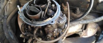
You can buy a subwoofer at any specialized car audio store. There are both passive and active models on sale, designed for any power. You can buy a passive speaker and a separate ULF unit. Despite the large selection, many prefer to make the box and amplifier for the car subwoofer with their own hands. The design must reliably operate from the vehicle’s on-board network, provide appropriate output power and a certain coefficient of nonlinear distortion. The low frequency device must be built securely to withstand constant shaking and vibration. Amplifier circuits for subwoofers can be implemented using bipolar transistors, field-effect components or integrated circuits.
Homemade subwoofer amplifier
It is better to make an amplifier for a subwoofer with your own hands using an integrated circuit. A large number of integrated components are now produced that work stably from a car battery, provide good performance and are reliable in any operating conditions. A circuit assembled on discrete elements contains a large number of solders and connections, which has a negative effect when operating in conditions of constant vibration. The design for a car subwoofer can be assembled according to one of two schemes:
- Class AB
- Class D
The analog version with low efficiency, average power and high quality reproduction of the entire spectrum of sound frequencies is well suited for a car. Low-frequency Class A systems provide better performance, but they are rarely used in real-life conditions. Class D or digital circuit provides high efficiency and high power output. Due to the special operating mode of the output semiconductor devices, the sound contains nonlinear distortions, causing the sound to take on an unnatural hue.
Powerful DIY subwoofer amplifier
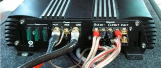
You can make a simple amplifier for a subwoofer with your own hands using the TDA1562Q chip. The integrated circuit is a powerful ULF that is suitable for building car sound systems. The advantage of the TDA1562Q is that the unit assembled on it does not require a bipolar power source for its operation and can be connected directly to a car battery. The reproduced frequency band starts at 15 Hz, so the microcircuit is suitable as a low-frequency amplifier for a subwoofer. At a 4 Ohm load, the rated power is 50 watts with a harmonic distortion of 0.05% and a signal-to-noise ratio of 90 dB. At a load of 8 Ohms, the power drops to 30 watts. The maximum power reaches 70 watts. The minimum and maximum supply voltage of the microcircuit is 8 and 18 volts, respectively. To ensure normal thermal conditions, the microcircuit must be installed on a radiator with an area of at least 400 cm2. A homemade subwoofer amplifier contains a small number of discrete elements.
Before I start my article, I want to say that if you have strong nerves, a lot of free time, certain skills in electronics, like to listen to very loud music in the car, powerful bass and are willing to spend a lot of money on such a project, then this article is just for you !
The idea of creating a high-power amplifier has been around for a long time, but due to lack of time and finances, the project was postponed. And then summer... vacation... It was decided to turn the idea into reality and exactly 3 months were spent for this, since there were big problems with the parts, but despite this, the amplifier complex was successfully assembled and tested.
To begin with, I would like to clarify the meaning of the expression “enhancing complex”. The fact is that it was decided to assemble a high-quality amplifier that could power the entire car audio system. The entire power section (power amplifiers) had to be combined “under one roof”, the result was 5 separate amplifiers with a total power of 680 watts, do not confuse with Chinese watts, there is a pure 680 watts of rated power, the maximum power of the system reaches 750 watts. The requirements for the complex were as follows. 1) High sound quality 2) High output power 3) Relatively simple design 4) Low cost compared to the prices of factory systems of this kind 5) Ability to power 10 -12 speakers + subwoofer To implement this idea, 5 separate power amplifiers were used, including a high-quality amplifier based on the Lanzar circuit to power the subwoofer channel.
Below are the parameters and series of microcircuits that were used in this amplifier. TDA 7384 - 4x40W (2 pieces, total chip power 320 watts or 8 channels, 40 watts per channel) TDA 2005 - 1x20W (2x10W) (2 pieces, total power 40 watts or 2 channels 20 watts each)
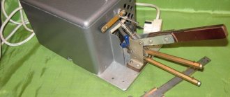
The above microcircuits are designed to power front speakers. This solution is the most economical; to create an amplifier of this kind, you can find out about the monetary costs at the end of the article. The most difficult part in any amplifier of this kind is the voltage converter, it is designed to power the subwoofer amplifier, perhaps we’ll start with it. Voltage transformer
It took me exactly two weeks to create.
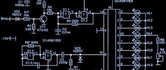
The voltage converter pulse generator (from now on PN) is built on a traditional TL494 microcircuit. This is a high-precision push-pull PWM controller, a domestic analogue of 1114EU3/4. The microcircuit does not contain an additional output amplifier. The additional stage is built on low-power transistors, the signal from them is fed to the gates of the field switches.
The circuit is known as a push-pull or push-pull converter. The circuit is not new, but I had to change some of the circuit values to suit my needs. On each shoulder there are two powerful field workers of the IRF3205 series. Through heat-conducting gaskets they are mounted on heat sinks that were removed from computer power supplies
In the rectifier part, KD213A diodes are used, they are just for such purposes, since they can operate at frequencies of 70-100 kHz, and the maximum current reaches 10 amperes; in this circuit, the diodes do not need additional heat sinks, I did not notice any overheating.
I used 2 relays for power supply, 20 amperes each, but it is advisable to install a relay for 50-60 amperes, since the converter draws a considerable current. The remote control system (REM) is implemented in the PN, i.e. No powerful switches are needed to turn on the subwoofer. By applying plus to the remote control, the relays are instantly activated and power is supplied to the converter.
I especially struggled with winding the transformer, since the transformer was of my own design. Unfortunately, I could not find ferrite rings, so I had to go for an alternative solution. We got several computer power supplies for free, and large transformers were soldered out of them.
The ferrite halves are tightly glued to each other, so they need to be heated with a lighter for 30 seconds, then carefully removed from the frame. As a result, the standard windings were unwound from the transformers, and the terminals were cleaned.
Next, the side wall of each frame was cut off.
At the end the frames are attached to each other. The result is one elongated frame onto which we can freely wind the windings we need
Through experiments, the required number of turns in the primary winding was found. As a result, the primary winding contains 10 turns (2x5vit) with a tap from the middle.
Winding was done immediately with 5 strands of 0.8 mm wire. First, 5 turns are wound along the entire length of the frame, then we insulate the winding and wind another 5 turns on top identical to the first. We wind the windings IN THE SAME DIRECTION, for example clockwise.
After winding the wires, we twist them into a pigtail, not forgetting to remove the varnish in advance, then we tin them and cover them with a layer of tin. Now you need to phase the windings. In fact, there is nothing difficult here, you just need to find the “beginning” and “end” of the windings and connect, for example, the beginning of the first winding with the end of the second or the beginning of the second with the end of the first, the connection point is a tap to which the plus from the general power supply is supplied ( see diagram). After phasing the windings, we wind a test secondary winding; it is needed so that if the phasing is incorrect, we do not wind the entire secondary winding. The test winding can contain any number of turns, for example 3 turns with 0.8 mm wire, then we assemble the transformer by inserting the core halves.
When turning on the circuit, the transformer should not emit a “buzz”; the transistors should not overheat if the converter is idle. We connect a 12-volt incandescent lamp of a couple of watts to the secondary winding, which should light up with almost full heat, while the transistors should be cold and only after a few minutes of operation you can feel a slight heat release. If everything is normal, then remove the test winding and wind in its place a normal one, which is wound according to the same principle as the primary.
This time the winding is wound with two strands of 0.8-1mm wire and contains 30 turns (2x15 vit). Two identical windings are wound, each with 15 turns and stretched along the length of the entire frame. After winding the first half, we insulate the winding and wind the second one on top. The windings are phased according to the same principle as the primary.
After winding the secondary winding, the wires at the ends are twisted and tinned. At the final stage, the core halves are strengthened. The transformer is ready!
IMPORTANT! In converters of this kind (push-pull) there should be no gap between the halves of the core! Even the slightest gap of a fraction of a millimeter will lead to a sharp increase in the quiescent current and overheating of the field-effect transistors! It was because of my clumsiness that I burned several field-effect transistors. Make sure that the ferrite halves are pressed against each other as tightly as possible. Such a transformer is capable of providing the required voltage and current to power the subwoofer amplifier. We solder the transformer onto the board and begin winding the chokes.
Chokes The circuit uses 3 chokes. They are designed to filter out RF noise and interference that can form on the power lines. The main choke is used on the positive power line of the converter. It is wound with 4 strands of 0.8 mm wire. The ring used those in computer power supplies. The number of throttle turns is 13.
The remaining two chokes are located after the diode rectifier in the PN, they are also wound on rings from computer power supplies and contain 8 turns of 3 cores of 0.8 mm wire.
To be honest, I didn’t expect that such a high-quality voltage supply would be obtained, the quiescent current of the circuit does not exceed 200 mA, this is normal for such a monster, the output voltage is +/-63 volts, the slope is insignificant, only half a volt. The maximum power of the converter would allow powering two of these amplifier, but here it works with a large margin.
Amplifiers based on TDA2005, for low-power heads
Assembling this block took only 2 hours. During this time, two identical power amplifiers were assembled. The amplifiers were chosen as the cheapest option for low-power speakers; they can be used to power speakers located on the front panel of the car. Each microcircuit develops 20-24 watts of power and has very good sound quality.
Each microcircuit is connected via a bridge circuit; with a stereo connection, one microcircuit is capable of delivering up to 12 watts into a 4 ohm load
The microcircuits are installed on the heat sink through an insulating gasket. The volume is adjusted in advance using a regulator. At first, another board was planned, amplifiers were assembled from this one, then a general board was invented, which was entered into the project archive.
TDA 7384 for front speakers
For more powerful speakers, TDA 7384 quadraphonic microcircuits are used. Each microcircuit is capable of delivering up to 40 watts of power per channel into a 4 Ohm load. The result is 8 channels of 40 watts, sounds very good.
Such microcircuits are used in car radios; if you are too lazy to buy them, you can get them from non-working radios.
Microcircuits have different filters independent of each other; if you use a common filter, then noise and excitation are possible. Both amplifiers start working when +12 volts are supplied from the battery to the REM pin. The amplifiers were assembled on one board, but later the blocks had to be rearranged, so each amplifier was implemented on a separate board.
Subwoofer amplifier
The famous Lanzar circuit, full description, assembly, circuit and configuration are described here, so there is no need to talk about this amplifier. The amplifier is completely assembled using transistors, has very good sound quality and increased output power. I made some changes in the diagram and below is the diagram I used to assemble it, the original diagram in the same forum thread.
Since I could not find some of the circuit ratings, I had to make some changes, in particular the emitter resistors were replaced with 0.39 Ohm 5 watts. The BD139 transistor was replaced with a domestic analog KT815G, in addition, the low-power transistors of the differential stages and pre-output stages of the circuit were replaced.
Electrolytic capacitors can be removed at the input if the input is replaced with 2.2 µF or more.
It is advisable to do the first start-up of the amplifier with one pair of output transistors with the input shorted to ground, so that in case of breakdowns the transistors of the final stage do not burn out; they are the most expensive thing in this amplifier.
Pay special attention to the installation of the circuit, monitor the pinouts of the transistors and the correct connection of the zener diodes, the latter, if connected incorrectly, work like a diode. I installed a regular quiescent current regulator, I do not advise anyone to repeat my mistake, it is better to install a multi-turn one, it can be used to accurately adjust the quiescent current of the circuit, also convenient for setup.
The output stage of the amplifier operates in AB mode, this is essentially a fully symmetrical circuit, the level of nonlinear distortion is reduced to a minimum. Due to its high performance, this amplifier belongs to the Hi-Fi category; getting 300 watts from this amplifier is not a problem. It is also possible to connect a 2 Ohm load at the output, i.e. you can power as many as two subwoofer heads by connecting them in parallel. In this case, you cannot raise the amplifier voltage above 45-50 volts.
You can increase the power of the amplifier by adding one or two more pairs of output transistors, but do not forget about increasing the power supply, since the output power of the amplifier directly depends on the power supply.
AC protection
Despite the fact that the power amplifier is quite reliable, sometimes problems can occur. The output stage is the most vulnerable part of any amplifier; due to the failure of the output transistors, a constant voltage is formed at the output. The constant disables the expensive dynamic head. Any amplifier of this kind has protection that will protect the speakers from constant voltage. When the amplifier is turned on, the relay closes, including the head; with a constant voltage at the output of the PA, the relay opens, maintaining the head
The protection has a relatively simple circuit, contains 3 active components (transistors), a 10-20 ampere relay, and the rest is little things. When the PA is turned on, the relay closes with a slight delay. Power for protection is supplied from one arm of the converter, through a limiting resistor of 1 kiloohm, select a resistor with a power of 1-2 watts.
Low-power transistors can be replaced with any others whose parameters are similar to those used. The relay is connected to the collector of a more powerful transistor, therefore, the final transistor needs a more powerful one. From the domestic interior, you can use transistors KT 815.817 or more powerful - KT805.819. I noticed heat generation on this transistor, so I mounted it on a small heat sink. Protection and output signal indicator are mounted on one board.
Stabilization block
Bipolar voltage stabilizer provides the necessary voltage to power the filter unit and audio signal indicator. Zener diodes stabilize voltage up to 15 volts.
This unit is assembled on a separate board; it is advisable to use zener diodes with a power of 0.5 watts
Audio level indicator
I won’t go too deep into the operation of the circuit, since the circuit of such an indicator is described in one of my
article.
The indicator uses LM324 microcircuits. It is advisable to use an operational amplifier for these purposes, since the microcircuits cost only $0.7 (each). The indicator uses 8 LEDs; you can install any LEDs that are at hand. The indicator operates in the “column” mode. The indicator is powered by a voltage converter, then the voltage is stabilized to the desired value and supplied to the level indicator. The indicator is connected to the output of the power amplifier, using a trimmer we adjust the indicator to the desired level of LED response.
Adder and low-pass filter block
The adder is designed to sum the signal of both channels, since we have only one subwoofer. After this, the signal is filtered, frequencies lower than 16Hz and higher than 300Hz are cut off. The control filter cuts the signal from 35Hz - 150Hz.
Assembly
After a thorough check of all blocks, you can begin installation.
Unfortunately, I couldn’t find a case from a DVD player or anything else convenient. I attached indicator LEDs to the front panel, where the display used to be located. All boards are attached to the bottom of the amplifier through insulating washers, which in turn were removed from domestic equipment
All microcircuits and transistors are screwed to the heat sinks through insulating gaskets. It is advisable to use thermal paste; unfortunately, we do not sell it, but even without it everything is not so bad. The input connectors of the amplifiers were soldered out of the DVD, and a connector from the car radio was used as output terminals.
My design uses only one cooler, it is designed to cool the heat sinks of the PN and TDA7384 power switches; the subwoofer amplifier does not need forced cooling, since for it I selected a huge heat sink that practically does not heat up. The power wires of each amplifier are connected to common power terminals. REM control allows you to turn off any of the amplifiers (for example, a pair of TDA 2005) at the right time. Each amplifier is powered through relays, which are activated when positive is applied to the REM pin.
Each of the amplifiers has a separate remote control system, which is located on the contact platform on the side of the housing.
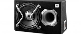
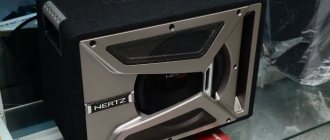
Subwoofer box
A couple of months after the start of assembly, I managed to buy a SONY XPLOD XS-GTX120L subwoofer head, the head parameters are below. Rated power - 300 W Peak power - 1000 W Frequency range 30 - 1000 Hz Sensitivity - 86 dB Output impedance - 4 Ohms Frequency range - 30 - 1000 Hz Diffuser material - polypropylene
Since stores only sold laminated chipboards, and we don’t have MDF at all, we had to choose from what was available. Fortunately, we were lucky with the material. Chipboard from USSR times was perfectly preserved in the attic, thickness 22 mm.
Next, the store purchased self-tapping screws with a length of 50mm (50 pcs.) and white silicone sealant (if available, buy transparent). The box was calculated using the WinISD program. Volume is about 83 liters.
The diameter of the FI port is 14 cm, the length of the pipe is 7 cm. A hole with a diameter of 28 cm was cut for the head. After making all the parts of the box, it was time to assemble it. It is convenient to start assembly by joining the bottom and front of the box. First, holes for the screws were made with a drill (with a small diameter drill), and only then the screws were screwed on. Before this, the fastening points were covered with PVA glue. There is no need to spare glue, so as not to complain about whistling later. I got a pretty good box, I worked as neatly as possible. Finally, the seams were coated with silicone on the inside of the box (silicone has an unpleasant odor, so this work should be done in a garage or outdoors). After assembling the box, I couldn’t resist, put the head where it was supposed to be and turned it on
I cannot convey this in words or even in a video, because it needs to be felt, not heard. You can feel the full volume of the box, the scope of the head, the power and quality of Lanzar, and all this is embodied in pressure on the chest…. It’s impossible to describe this in words, and only then do you begin to understand that everything around you is collapsing and falling apart, the glass is moving on the table by itself, the glass is beginning to “swell” from the pressure. In a word, everything in the house was under a “dose” of vibration.
Next, the box was covered with carpet. Carpet 120x200mm, enough for the entire box.
We sold special glue for carpet, but a can of aerosol costs $25, so we had to use PVA glue. To begin with, I sanded the box; this process took me 4 hours. Apply PVA glue to the already cut carpet. After this, the box needs to be “rolled” over a pre-cut carpet. We wrapped the box, now in order for the glue to dry properly, we hammer small nails along the edges, then after drying they can be removed or left.
Then we cut out the holes for the head and the bass reflex. The head is attached to the box with ten self-tapping screws, this ensures tight contact, no additional gaskets are needed.
The output contacts of the box are made from a connector for the network cable of a computer power supply unit; the manufacturing process is clear from the photographs.
This alternative solution is again caused by a shortage of factory connectors.
It turned out well. A separate hole was cut for it. On the inside, after sealing the wire, the connector hole was sealed with silicone sealant to avoid whistles and unwanted noise.
Total construction costs
Voltage converter: BC557 3pcs - $2.5 TL494 1pc - $1 IRF3205 4pcs - $10 Diodes KD213A 4pcs - $4 Polar capacitors - $10 Non-polar capacitors - $3 Resistors - $2 Chokes and transformers - from old PC power supplies Relays - from a voltage stabilizer
Lanzar amplifier: Transistors 2SA1943 2pcs - $6 2SC5200 2pcs - $6 2SB649 2pcs - $2 2SD669 2pcs - $2 2N5401 2pcs - $1 2N5551 2pcs - $1 Resistors 5 watt - 4 pcs - $3 Other resistors - $4 Non-polar capacitors — 3$ Polar capacitors - 5$ Zener diodes - 2 pcs - 1$
Other amplifiers: TDA7388 2 pcs - $15 TDA2005 2 pcs - $2.5 Resistors - $2 Non-polar capacitors - $4 Non-polar capacitors - $6
Filter block: TL072 1 piece - $1 TL084 1 piece - $1 Non-polar capacitors - $3 Resistors - $2 Regulators 3 pieces - $4
Indicator block: LM324 2pcs - $2 LEDs and everything else - $2
Stabilizer block: Transistors $2 Zener diodes 13 volt 6 pcs - $1.5 Stabilizers 7815 2 pcs - $1.5 Zener diodes 7915 1 pc - $0.7 The rest - $2
AC protection: Transistors - $2 Relays - everything else is free $1 Plugs, sockets and connectors were fortunately in stock
Subwoofer box: screws 50 pcs - $0.5 Sealant 2 bottles - $2
Chipboard - free PVA glue - free Head - $65 Carpet - $15
Results
That's all. I'm pleased with the results, very pleased! It is not possible to buy such an amplifier; amplifiers of similar power cost from $400! Although Chinese manufacturers offer for significantly little money, quality and reliability... In general, the amplifier turned out to be a thrice cheers! Everything works great, all you have to do is buy a car and enjoy your hand-made amplifier, while the amplifier will work at home for now, from a powerful 12-volt power supply.
The author of the project is AKA KASYAN. E-mail E-mail address is protected from spambots. Javascript must be enabled in your browser to view the address.
Homemade amplifier for a subwoofer in a car
The circuit is assembled on a printed circuit board made of foil PCB. It is better to use film capacitors C1 and C2. In case of an emergency, the red LED lights up intermittently. Such a situation is overheating of the microcircuit case, large signal distortion or a short circuit at the output.
A do-it-yourself amplifier for a subwoofer in a car can be mounted in the same housing with the speaker or installed separately. It is necessary to provide air access to the radiator so that the microcircuit is cooled properly. The current consumption of the device can reach 10 A, so you need to install a fuse block in the power circuit, and connect the amplifier to the battery using a thick power cable.
Subwoofer connection problems
If you connect subwoofers yourself, problems with its operation may arise. The most common errors are incorrect connections, as well as poor contact or the use of conductors of insufficient cross-section.
Examples of problems that users have encountered:
- After connecting the subwoofer, the power is activated, the “power” indicator lights up, but no sound is played. The reason for this behavior is insufficiently good contact with the masses. It is recommended to install an additional ground cable from the battery. The cable must have a cross-section comparable to the grounding cross-section of the amplifier.
- Some radios are equipped with line outputs designed for installing only an active subwoofer. The passive device is connected via an active analog signal converter. When connected directly, the subwoofer is quiet and intermittent. Using a converter involves connecting the main speakers through an amplifier.
- When an active subwoofer is connected to two RCA signal cables coming from the radio, the volume decreases. Disabling one input restores operation. This is due to the fact that the amplifier has a so-called signal doubler in its design. In this case, it is enough to leave one cable and not use the second.
- The active speaker is installed via RCA tulips. The sound is quiet; when you try to turn up the volume, noises and wheezing occur. The reason may be insufficient wire cross-section or a faulty line output fuse (available on radios from a number of manufacturers, for example, Pioneer).
DIY 10 W amplifier for subwoofer
If more power is not required, then an amplifier for a subwoofer can be assembled using an integrated circuit or transistors. A very good ULF circuit for a subwoofer can be assembled using the TDA2003 integrated circuit. If you use only one case, the output power will be about 10 watts. For low-frequency car speaker systems, a bridge connection of two microcircuits is often used. This inclusion allows you to get up to 25 watts into a 4 ohm load. The circuit is powered from the vehicle's on-board network. Since the number of discrete elements in the circuit is small, the printed circuit board can be designed independently. You can make an amplifier for a subwoofer without a printed circuit board by soldering the elements on a breadboard with stands or petals. To avoid overheating of microcircuit cases, they must be mounted on radiators with heat-conducting paste.
Power converter UMZCH subwoofer
This converter is based on TL494 (KA7500) driver. There is overvoltage protection - it turns off if the voltage exceeds 15 volts at the input. Undervoltage protection will protect against severe battery discharge - the driver will be turned off if the voltage drops to 9 V. Current protection takes care of the output transistors and the overall safety of the entire circuit. A green diode means normal operation, a red diode means one of the protections has disabled the driver. The soft start circuit allows the converter to start slowly despite the large output capacitances.
You can make your own transformer or take one from the ATX unit (in the computer power supply). Use 5V and 12V lines, the transformation ratio will be 2.4x. This means that if we supply 14V of battery voltage across a 5V line, we get 2.4x the voltage on the 12V line - about +/-33V to power the amplifier chip. This is a very good and simple solution. Switching frequency - 50 kHz. You can change it by installing a capacitor on pin5 of the TL494. For example, 1nF will give a frequency of about 50 kHz, 1.5nF - 30 kHz.
You can replace the IRFZ44N field-effect transistors with other transistors, you just need to provide more than 100 W of output power, and IRFZ44N up to 300 watts.
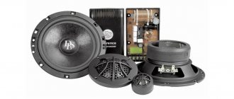
How to build a music amplifier for a subwoofer
Many radio amateurs use low-frequency channel circuits with high output power, but this parameter is limited by the supply voltage of the vehicle's on-board network. To obtain good power, you will need a voltage converter, since most microcircuits operate on bipolar voltage, the value of which exceeds the capabilities of a car battery. You can make your own amplifier for a passive subwoofer using the TDA7294 chip. You will only need to assemble an amplifier for an active subwoofer if its output power is too low. You can assemble two similar circuits and organize a bridge connection of the load. The output power will increase to 200 watts, but the load should not be less than 8 ohms. To make an amplifier for a subwoofer in a car, you will need a voltage converter. Chips must be installed on radiators to avoid overheating of the case. You can install a computer cooler in the speaker, which will cool the radiators of a powerful amplifier
Description of devices
The term subwoofer refers to an acoustic speaker or system capable of reproducing sound waves in the frequency range of 20-120 Hz. The work is based on the principle of converting electrical signals from an amplifier into sound. For this, an electromechanical device is used - a speaker, which has a special design that ensures the generation of low-frequency sound signals. To improve the sound, it is installed in a housing with a strictly defined volume. Parts of the housing and speaker suspension should not create extraneous sounds (creaking).
Design features of subwoofers
There are several designs for installing the speaker:
- Open speaker installation or unrestricted acoustic baffle. The element is placed on a box with a large volume. On a car, a similar box is the luggage compartment in cars with a sedan body type.
- Installation in a small closed box. The dimensions of the box impose restrictions on the frequency ranges, cutting off the very bottom.
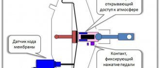
- Bass reflex housing. In such a device, a channel is used that has certain overall dimensions. The bass reflex is based on the effect of the meeting of waves emitted by the outer and inner sides of the speaker.
- A strip body, which is a bass reflex with an additional bulkhead. The speaker is located inside, on the partition. The sound is transmitted through the bass reflex hole. The design is used to create small-sized devices with improved sound parameters.
- The housing of a passive radiator, which is a combination of active and passive speakers with identical characteristics. The elements operate in antiphase. Due to the distance and dimensions, which are calculated individually for each device, it is possible to obtain clear sound with a low frequency.