Spot welding is a subtype of resistance welding. In this type of welding, metal elements are fastened in one or more places.
This surface welding method has high production technology and a variety of applications in various industrial fields, and can be used in the production of electronic devices, automobiles, ships, aircraft and other industrial production fields.
When using this type of welding, a very high strength of connection between structural parts is achieved. The degree of strength at the junction is determined by the efforts to squeeze the surfaces of the fastened elements and the physical force of the device's electric current.
In modern production, different versions of these devices are used, from stationary machines to easily transportable devices. As an example, the picture shows a photo of a manual spot welding machine.
Hardware Features
This type of welding is based on the method of heating a metal part (plate) with an electric current pulse. To ensure the welding effect, the parts (elements) are strongly pressed together.
At the point of greatest compression, parts are spot welded by passing an electric charge between the electrodes of the device. At the point of contact, a molten point of metal no larger than twelve mm in size is formed.
Features and principle of operation
Spot welding works using a powerful short-term electrical pulse supplied to the electrodes from an inverter. The parts are heated to their melting temperature, then they are connected to each other. At the junction site, a strong weld remains between the two electrodes. The peculiarity of the work is that the place of spot welding is limited by the diameter of the electrode used.
Before combining the two metal parts, they are pressed tightly against each other. After resistance welding, they need to be kept under pressure.
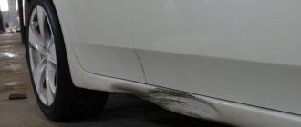
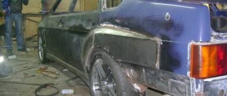
Spot welding allows you to weld metal in small areas of a car body during body work, solder wires and small parts together, and repair electronics.
Spot welding methods
This type of welding is conventionally divided into two methods: soft and hard.
Soft mode. In this mode, when welding, the parts are gradually heated using a low current. It takes about three seconds to weld metal surfaces in this mode.
In this mode, the power consumption of the machine (device) is reduced. The mode is usually used when welding metals with hardening properties.
Hard mode. It is determined by a short duration of high electric current and powerful squeezing of the welded elements at the welding point. The density of consumed electric current in this mode reaches 300A per 1mm2. The welding process takes up to one and a half seconds.
The main disadvantage of this method is the large demand for electricity (machines) and large overloads of the industrial network. The advantage is minimal time for welding surfaces.
This mode is usually used when welding surfaces with good thermal conductivity, high-alloy steel or bonding surfaces of different thicknesses.
How resistance welding works
This is a thermomechanical type of welding. Before starting work, the welded parts are arranged in the desired position. Next, each part of them is fixed between hardware electrodes, under their action the parts are compressed.
The current passing through the electrodes heats the parts, and an alloy is formed at this point. It is the connecting element of two parts. Devices of this type in production have high productivity. They are capable of making 600 weld points in a minute.
But in order for the surfaces to become hot and begin to melt, an electric current of enormous strength is supplied to them. Such an impulse leads to almost instantaneous melting of metals. Its duration depends on the type of metals being fused. Typically the time range is 0.01-0.1 seconds.
In this case, the molten metal surfaces form a welding drop between themselves, which must harden. To do this, the welded parts are kept compressed for some time. The molten drop at this moment forms a kind of crystal lattice.
Pressure plays an important role in this process. It prevents the molten drop from spreading over the area of the parts, thus being held together at one point. The compression force is gradually reduced, then the weld is better set. This work requires clean surfaces of the parts.
Therefore, before work, the intended location of the weld is treated with a special solution. This removes corrosion elements and other oxide films. The result is a high quality seam.
Welding methods
There are several methods for spot welding:
Spot - welding of elements occurs in one or many places. It is used in instrument making, the automotive industry, and the construction of sea, river and aircraft vessels.
Provides welding of steel sheets up to twenty millimeters thick.
Relief method - structural elements are welded in one or several prepared places. The difference between this method and the previous one is due to the shape of the fastened elements at the welding site.
Seam method - the welded elements are fastened with a series of welding seams. A seam can consist of individual weld pixels or overlapping ones. Used for the manufacture of various tanks requiring a high degree of tightness.
How to assemble a simple welding machine at home: drawings of inverter models and step-by-step assembly instructionsDo-it-yourself welding table - step-by-step instructions for manufacturing and assembly (65 photos)
What types of welding machines are there: types, principles of operation and classification of devices
Docking - elements are welded along the adjacent contact area under high temperature. They are used in laying pipelines and making anchor chains for ships.
We make the welding ourselves
This type of welding tool is not a cheap tool. It is more practical to make a spot welding machine with your own hands.
The main element of such a device is a transformer (used in various household appliances). To provide the necessary electric current for this type of work, it is necessary to rewind its windings. During the creation of the 1st winding, intermediate terminals are also prepared. The wire on the windings must be impregnated with varnish and wrapped with special paper.
The components of the device are selected according to the parameters of the transformer. Its design depends on the parts (surfaces) to be worked on. Electrical elements must be designed with a high degree of reliability.
Pincers can be of two types: stationary and remote. Stationary ones are simpler to manufacture; they are firmly fastened together and reliably insulated. Remote ones are more suitable for use when performing various types of work. They can be easily installed and removed. It is convenient to bring them to the place of direct welding.
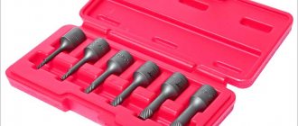
When using external pliers, it is necessary to ensure their reliable connection to the device itself and their waterproofing. To make electrodes, you can use copper rods, bronze or an old soldering iron tip.
The electrical diagram for connecting such a device can be easily found on the Internet.
Spot welding under a microscope
Hamsters welcome you, friends! Today's post will be devoted to a machine for spot welding of 18650 batteries and others. During the process, we will assemble such a device, analyze the basic principles of its operation and examine the welded areas in detail under a microscope. Batteries are going to have a tough time today. It would seem like a welding machine that literally consists of one transformer and a controller, what could go wrong here?!
Imagine that one fine morning your screwdriver died. Turning screws with a screwdriver is not a royal task, so you need to solve the problem. The culprits of this incident were nickel batteries that prematurely went to Valhalla to drink wine and fight with swords. They have been replaced by compact, high-current lithium-ion batteries, which are many times superior in performance to their predecessors. According to the technology, such banks are connected by spot welding, which welds the conductive tape to the body of the battery. It is not recommended to use a soldering iron here because of the possible overheating of the battery’s internals, which can lead to premature failure. We install the so-called BMS board with a balancer on the assembly and assemble the screwdriver. Now it works like new.
Vitya gave me the idea to create a welding machine.
A man who literally repairs everything. To repack batteries in various devices, he uses a resistance spot welding machine. The connection here is so strong that the tape literally comes off completely. I was impressed by this device, and I needed to figure out what and how it works.
In fact, everything turned out to be quite simple.
The heart of the device is a transformer from a microwave with a rewound secondary winding, and a controller that ensures the connection of the primary winding of the MOT to the supply voltage for the required time to form a welding pulse. We also need a power supply for the controller, a pair of copper cable lugs, and a network cable with a cross-section of 1.5 square meters. mm. and a housing that will house all the electronics. I had a 700 W MOT lying around for a long time with a cut off secondary winding, and just had a reason to attach it somewhere.
We remove the magnetic shunts and carefully clean the holes where the thick wire will be inserted. We pay special attention to the edges; they are quite sharp and can easily damage the cable insulation.
As for the cable itself, it’s better not to save money and take this guy.
RKGM with a cross section of 25 sq. mm. Made in Russia "Rybinskkabel". This is a clever multi-core wire with insulation made of silicon-organic rubber of increased hardness, braided with fiberglass impregnated with enamel or heat-resistant varnish. It is very thin and flexible. The wire insulation is absolutely indifferent to elevated temperatures; the flame of a lighter is barely capable of causing at least some smoldering. The length of the heat-resistant kite is 2.2 meters.
Lubricate the internal holes of the magnetic circuit with Vaseline.
We carry out the same procedure with the cable. Even though the cable is quite thin compared to its cheaper counterparts, you should try to fit 4-5 turns into the transformer. But here's the problem. 700 W MOT allows you to accommodate only 3 turns. No problem! A system of levers and screwdrivers comes to the rescue. In general, use your wits and wind 4 turns into such a small transformer.
Cable lugs.
Good, copper, 25 square meters. According to the technology, they need to be compressed with a special hydraulic press. Soldering is not considered here due to the possible heating of the wire during further experiments. The wire is crimped here in a 6-sided matrix, which evenly crimps the copper sleeve from all sides, creating a high-quality connection. After crimping, small ears may form on the tip; they must be removed with a file. As a result, we will have beautiful crimped lugs at the ends of the wire.
Now they need to be connected to the copper bars on the handle for resistance welding.
The bolt here is 8 mm in diameter and 20 mm long. Be sure to install the Grover washer; it will provide reliable clamping if the connecting unit becomes loose during operation.
The simplest handle for contact welding can be ordered on Aliexpress.
But I liked a more advanced version created by a folk craftsman. His name is Gennady Zbuker. He assembles welding machines himself, supplements them with handles that he designs and prints on a 3D printer. This design is called a spot welding electrode holder “ZBU 5.1” with a button and springs. 3D models of early versions of such pens can be found on the Thingiverse website; the author made sure that, if desired, everyone could make a similar holder for electrodes with their own hands. It deserves respect! You can also order consumables on his website (not an advertisement, but a recommendation).
As for the resistance welding handle.
It is made quite well. The body is printed using ABS plastic. The peculiarity of the “5.1” version is that there are two fans on board that are capable of cooling the copper busbars during continuous operation. They are powered by 5 volts via a micro USB connector. Current consumption is no more than 300 mA.
From practice, I will say that during all the experiments I did not manage to heat the handle.
The electrodes here are spring-loaded and have a “limit switch” button, which, at a certain pressing force, is triggered and gives a command to weld. This compression ensures good electrical contact with the welded surfaces, guarantees repeatable quality of weld spots, and eliminates the formation of sparks and battery burns. It is precisely because of the heating and simultaneous compression of the workpieces that this welding method was called “electric forging.” If desired, the design of the electrodes on the handle can be changed for double-sided welding.
The electrodes are made of heat-resistant chrome bronze BrKhTsr.
Since electrodes wear out quickly during welding, they are required to maintain their shape when heated to 600 degrees and compressive shock forces of up to 5 kg per square millimeter. During operation, such electrodes do not particularly stick or burn. The battery welding current pulse must be very short, otherwise there is a chance of burning a hole in the housing, which will lead to its failure.
The task of controlling the pulse duration lies with a fairly simple controller, which was taken from one site.
The device is assembled on the basis of Arduino NANO, using a liquid crystal display to display useful information. Menu control is carried out using an encoder. I thought it was elementary and simple, and began to assemble the device from the modules available on the farm.
The functionality of the controller is quite simple.
It produces two consecutive pulses with a pause between them. The first impulse is called “additive”, and the second “main”. He welds the metal to each other. All pulse timing variables are adjusted using the encoder, including the pause between them. The power transformer is controlled using a fairly powerful 40 A triac. It is installed at the input of the primary winding. Marking BTA41-600.
For ease of use of the controller, all its modules can be placed on one board.
This will allow you not to get confused in a bunch of wires coming from the arduino. We poison the board and see how everything functions. The light blinks, which means the circuit is assembled correctly. The type of homemade boards today is gradually fading into decline, because it is more profitable to order their production in China. The price really depends a lot on the size, but that’s another question.
We place the controller modules for resistance welding according to their specified locations.
You've probably already noticed that the contacts on the board are gold-plated. It was interesting to see how they would perform during the soldering process. The peculiarity of gold-plated contacts is that they are not susceptible to various types of oxidation on the metal surface, which allows the boards to be stored for quite a long time. This is relevant for large productions. Solder also spreads over contacts like oil over a frying pan.
After assembling the device, you need to upload the sketch to the Arduino board.
We do this through the FL Prog program in just a few clicks. The program is uploaded to the brain in a couple of seconds and all the necessary settings for further welding are displayed on the screen.
Now let's make a beautiful control panel.
To do this, you need to mark all the necessary windows and future holes on the plastic panel. We carefully cut out the windows with a drill, and drill holes with the same screwdriver that we repaired at the beginning.
We place the MOT, a 12-volt switching power supply inside the case and push the network wire inside. Its length is one and a half meters. We distribute all the necessary wires to their connectors, and that’s basically it. We've sorted out the electronics.
As a result of all the manipulations, we got a rather beautiful controller for spot welding.
Power wires are routed through holes in the top cover of the housing. There is also a connector for connecting the limit switch button. Everything is aesthetically pleasing and simple. It seemed like it to me. All channel subscribers know that nothing happens just like that. Something must go wrong. And this is one of those cases! It's time to check the device in action.
For welding, take an old battery and 0.15 mm thick nickel tape.
Let's set the welding time to 20 ms for each pulse. This corresponds to one period of alternating voltage from the network. If there is 50 Hz, then this is one fiftieth. As a result of the tests, it turned out that at the shortest time delays, the tape not only cooks, but burns right through. Now it’s not a battery, but continuous ventilation...
On other cans, welding proceeded somewhat differently, the burn was less, but the tape between the electrodes heated up to red hot.
It was quite interesting. Moreover, on some batteries the tape was welded so that it was practically impossible to tear it off, while on others, with the same welding time, there was no effect at all. The tape literally came off the body, leaving only two dents on the metal. A digital oscilloscope, which is capable of recording a signal for further study, helped to understand the problem.
The reason for burning through the batteries was the operating time of the power transformer, which did not correspond to the established values.
The problem here is clearly a software one, since the developer’s sketch was repeatedly downloaded to another Arduino, but this did not produce any results. Now, according to our established parameters, the signal on the optocoupler should be 10 and 60 ms. But in fact, this time is several times longer, 80 and 125 ms. Naturally, this time is enough to overheat the nickel plate between the electrodes and burn the bottom of some batteries.
If there are programmers among you, I have a request, look at the code and correct the error there.
This is a good project in terms of simplicity and repetition, but it turned out to be a pig in a poke. We tried to understand the jungle of this code, but the most we had enough knowledge for was visualizing the image when loading the program. In general, I’m distant in these matters, and that’s okay! We need to get out of the situation.
In China there are ready-made controllers for spot welding, I order and wait.
This is one of the most advanced versions of the boards. Model NY-DO2X. In addition to the fact that it gives a double impulse with a pause, there is also the ability to adjust the power. The triac is installed here BTA100 designed for a current of 100 amperes. Operating voltage 1200 V.
We mark and cut out holes for the new control panel.
At this stage, we take our time so as not to cut off anything crooked. We see several connectors on the board. The first one on the left is supplied with an alternating voltage of 9 volts. The second one connects a button from the electrode holder or an external pedal. The second option is good if you have a handle without a button, or you just like working with pedals. The transformer for powering the board can be pulled out of some old power supply from a home phone. A current of 300 mA is enough.
In general, we are trying to weld the tape to the battery.
We press the handle, there is an impulse and what do we have here. The welding did not really occur and the tape stuck to the electrodes. It feels like a 700 W transformer doesn’t have enough power to weld the tape at short shutter speeds. No question, I get dressed and go to the radio market to buy more powerful microwave MOTs.
From left to right transformers: 700 W, 800 W and 900 W.
The larger the magnetic circuit, the greater the power. Here you can see how much the 900 W version is larger than its predecessor. Dimensions: length 106 mm, height 89 mm, width 66 mm.
More advanced welders can be made using software from domestic microwave ovens, but firstly, they require a huge body, secondly, the weight, and thirdly, not everyone can handle such a rare artifact. Let's not anger God, and let's put under the knife a transformer brought from the radio market. The most convenient way to cut off the secondary winding is with a hacksaw. Copper is quite soft, so it cuts quite quickly.
We knock the wire out of the core with an iron rod.
In total, this operation takes 20 minutes. We don’t throw away the copper braids, but sell them for metal and buy beer. Be sure to remove the magnetic shunts that are installed for soft operation of the magnetron and clean the edges of the holes in the magnetic circuit as shown earlier. Such a large transformer can easily accommodate 4 turns. If desired, you can accommodate the 5th one, but I did not transfer Vaseline) In series with a powerful triac, we solder the primary winding of the just rewound MOT. We don’t skimp on solder and do everything as if it were for ourselves.
The connection diagram is simply elementary.
Even a child can handle it. It's time to try out this "second" welding machine assembled in one film. In one of the next issues there will be a triple fiasco poured on top with a thick layer of chocolate, where I spent another 600 bucks by borrowing someone else’s infrared camera. In general, the channel is an expensive pleasure. Absorb other people's experiences and mistakes. Unlike me, you don't have to pay for them. Everything is free.
A short guide to using the Chinese controller.
Press and hold the red button for about 4 seconds. The device will then enter the mains voltage calibration mode. It must be set according to the actual readings of the multimeter inserted into the socket. It is not clear why this function is needed, but the set numbers will change in proportion to the network voltage.
What do the lights above the numbers mean?
The first LED indicates the presence of power. The second LED lights up when the button on the handle is pressed. The third lights up only when there is an impulse. In general, the first three red LEDs are purely informational. The fourth green light is the operating time counter, summing up each press of the pedal or “limit switch” inside the welding pile. The counter is reset by double pressing the red button. Next is the orange LED. The first sets the duration of the “first pulse”. It is selected in periods. Let's set one to equal 20 ms. The second LED sets the pulse power. Let's say 35 percent. Minimum 30 maximum 99.9%. The green LED between the orange ones indicates the pause between pulses. Same in periods. Let's set it to 2. The last two orange LEDs also determine the duration and power, but of the “second pulse”. Let's set it to 2 periods and turn the power up to 100 percent. That's all, now you can poke some tape and see how welding happens, study the points, select modes on the controller, and so on.
Brief characteristics of the resulting spot welding machine.
The weight of the finished device was 5.7 kg. The alternating voltage on the secondary winding of the MOT was 3.8 volts. The maximum current recorded during welding showed 450 amperes. One interesting effect is associated with this during operation of the device. The magnetic field of the wires turns out to be so large that they are scattered from each other by 20 centimeters. At the same time, the magnetic core quite strongly attracts any nearby metal, so I do not recommend using an iron case for the device; it will make unpleasant sounds when welding.
If the secondary winding is short-circuited, then even a 700 W MOT can load the network to values in excess of 4 kW. I don’t know how much more, since the wattmeter goes into protection when such a load is reached. In this case, the secondary winding current goes off scale beyond 600 A, above the measurement limit of the multimeter. At the input of the primary winding, the maximum current is fixed at 21 amperes, while the voltage in the network sags from 230 to 217 volts.
During continuous operation, the core of the MOT will heat up, in 4 minutes its temperature will reach approximately 52 degrees. And this is at idle without load. In practice, as the temperature rises, the transformer begins to cook harder, which can lead to burning out the battery. In this case, it is fair to blow the transformer using fans.
Let's move on to welding.
First, let's look at what the signal should look like on an oscilloscope. Settings: first impulse one period 30 percent, 2 periods rest, second impulse two periods, full power. We make a weld point and record the signal. We see how cut off the period of 30 percent power looks. After it comes a metal two periods of rest, and then comes a powerful impulse with a duration of two periods and a power of one hundred percent.
The controller, thanks to monitoring the phase transition through zero, opens the triac at 100 percent at almost zero increase in voltage amplitude. It is clear that the voltage and current flow with a slight delay relative to each other. At 50 percent, the controller opens the triac only at half the half-cycles of the mains voltage. This method is similar to Pulse Width Modulation. This mode is used in light controllers - dimmers. The brightness of an incandescent lamp will directly depend on the area trimmed by the sinusoid. In our case, this is necessary for all kinds of delicate welding.
Now our task is quite simple.
You need to weld the spot welding tape to the battery. But a couple of questions arise here. What kind of tape will we cook and to which battery? Remember the moment when our welder with a 700 W transformer refused to weld nickel tape? An identical situation occurs with the new 900 W ILO.
At the beginning, I couldn’t understand for a long time what the reason was, but there were two important points.
A high-current battery, unlike a regular battery, has a slightly thicker case wall. Perhaps the metal of the case is different. Our nickel tape is also quite tricky. In the sum of all these factors, even powerful welding is not able to give the desired result.
The solution to the problem is to replace the nickel tape with a steel one.
It also seems to be nickel-plated on top, but from now on we will simply call it steel. Welding on the same settings as before, the steel strip was welded with a bang. It is impossible to tear it off with pliers without destroying it. The assembled apparatus fully satisfied the assigned tasks.
Now let's look at the basic requirements for spot welding.
The duration and power of the pulses must be selected in such a way that the welded areas have as little overheating as possible. It appears as tarnished colors around weld points. This is not very good, since the metal partially burns out in these places, which can lead to a weakening of the strength characteristics of the connection. An ideal weld looks like this. There is no overheating, the dots are white, the tape comes off from the body of the battery with pieces. This is exactly the result we must achieve.
Underwater rocks.
There are a lot of them, first of all you need to understand the physics of current flow in metal. The metal at the point of contact with the electrodes represents the greatest resistance to the current and therefore the place will become very hot. Our task is to heat the metal to such an extent that a so-called welding core is created. Heating in this process should not occur under the electrodes themselves, but between the sheets of metal. In this case, welded cores must be done as quickly as possible, with a very powerful and short pulse. If you heat the welding site slowly, the heat will spread throughout the battery in all directions, without achieving the desired result.
Electrodes are a whole separate world.
Imagine you spent a long time preparing an assembly of 18650 batteries and at one point decided to sharpen them. The ends came out sharp and beautiful. But at the very first welding points we will end up with a burned-out battery, since the electrodes will most likely sink into the body of the can. Some of these batteries cost a fortune, and damaging one of them is unacceptable.
What's really going on?
The point is that the sharper the electrode, the smaller its contact area with the metal; as a result, at the same current, the place will heat up faster. The weld core forms so quickly that it causes all of the metal underneath the electrode to melt.
Another very important point: when welding, the electrodes must be kept strictly perpendicular to the battery.
They should not enter at an angle. A small bevel may form on the contact, which will sooner or later lead to burnout due to uneven current flow through the electrodes. Using this same example, it becomes clear why the first additive pulse is needed at low power.
What is affected by the distance between the electrodes?
In theory, the further apart they are, the better. There will be fewer losses on the upper shunt workpiece. But as practice has shown, here you can play with the settings, and no matter what the distance is, you can achieve good quality weld points. The width of the tape you work with plays a big role here.
In general, the settings for the duration and power of the pulses decide everything.
I was able to weld 0.2 mm. a tape with such strength characteristics that it came off along with fragments of the battery casing. All the batteries in the film were dead if anything.
Recommendations when choosing welding settings.
There are many factors in this matter that influence the final result. For example: you have selected a mode that works well with the same tape and batteries. But if you change one thing, the settings may also have to be changed. Now imagine that you have a bunch of different batteries, how will you cook? The power and welding time must be adjusted from lower to higher. We put an end to it, the tape came off, no big deal, we turn up the power and take a look. Now the tape comes off in pieces. Exactly what is needed. Well, do you understand everything?
I think it’s worth once again listing all the factors that may influence the final result of spot welding.
Electrical wiring in the apartment.
An extension cord with a wire cross-section of 2.5 squares was made especially for the film. Even despite this, the weak 700 W MOT managed to drain the network under load.
The main welding characteristics depend on the power of the transformer, the cross-section of the power wire, its length, the number of turns, and the quality of the connecting nodes with the manual contact line.
An important role is played by the material of the electrodes, the distance between them, sharpening and clamping force. The material of the tape for resistance welding, its thickness, width and shape, determines a lot. Battery type and wall thickness. Even the ILO temperature is worth taking into account.
Based on all of the above, in each individual case the settings for the first and second pulses on the controller are selected to obtain the best welded cores with the least tarnish colors.
The assembled resistance welding machine turned out to be quite compact and versatile.
He was going only to weld batteries for a screwdriver and a soldering iron from China, which requires 24 volt power. Portable tools are often missing during repairs. We printed the constructor in the form of cells for 18650 batteries on a 3D printer; they simplify the task of forming assemblies with different voltages and capacities, allowing you to stack the elements in any order. The assemblies are connected to each other by special grooves. Now repacking your old scooter yourself will not be difficult.
For reference.
Filming this episode took a little over 2 months. When I started studying this topic, I could not even think that there would be so many nuances here. The cost of the film's budget exceeded the expected boundaries, since it was necessary to buy spare parts for almost 2 welding machines. In total, 3 meters of nickel tape were used up and 2 good batteries were damaged. Two dozen bad ones were put to use. Well, that’s it, I’ve voiced the video, now you can go drink and get ready for the next release.
As Master Yoda said: It’s all so difficult to listen to you. Do you hear what I said? - You should feel the power, it’s between you, me and the stone, everywhere... - Yes... but no
Full video of the project on YouTube Archive with useful things Our Instagram
Safety precautions
To ensure their own safety, the worker must know and comply with the safety instructions for spot welding:
- To prevent electric shock, ground the unit;
- Before starting work, be sure to check its serviceability;
- use personal protective equipment for hands, eyes and body;
- exclude high voltage supply to the device controls
- use only wires of the specified cross-section in the device;
- carry out work in a room with well-equipped ventilation or use special masks to protect the respiratory system.
- locks and toggle switches (buttons) for turning on or off must be in working order, clearly visible and easily accessible;
- During work, the area of the clamping mechanisms must be covered with a shield.
Compliance with these safety measures will ensure the health of the employee and others and will allow the required amount of work to be completed accurately and on time.