Simple speed metronome
Tachometer comes from two Greek words: “tacho” meaning “speed” and “metronome” meaning “to measure”. It works on the principle of a generator and determines the voltage corresponding to the speed of the shaft. It is also known as a revolution counter. Principle of operation:
- induction;
- electromagnetic;
- electronic;
- optic.
Historically, the first mechanical tachometer was developed based on the measurement of centrifugal force. In 1817 they were used to measure the speed of traction machines, but after 1840 they were used primarily to measure the speed of vehicles. A digital tachometer is an optical sensor designed to determine the angular velocity of a rotating element. Areas of use:
- Cars, planes, tractors, trains, light rail vehicles and their repair.
- Laser tools.
- Medical use. A hematachometer is a device placed in an artery or vein that measures the speed of blood movement through a rotating turbine. The indications are used to diagnose circulatory problems such as thrombophlebitis.
- Analog audio recording that measures the speed of an audio tape.
- Estimation of traffic speed and volume.
Types of modern tachometers
An important parameter that is taken into account when choosing a device is the operating speed range. It sets the limit of the measurement that the device is capable of monitoring. Another parameter is accuracy, which is specified in units such as ± RPM. Sensor technology used: contact, photoelectric, inductive and Hall effect.
In a contact type device, it comes into contact with a rotating part. A photoelectric device uses light rays, either visible or infrared, to measure speed. The frequency of the break, which is used to calculate speed. Inductive instruments use magnetic elements to induce magnetic fields and an activation frequency to measure speed. Design features:
- counters;
- timers;
- strobe
Display configurations include analog visual indicators, digital or graphic video displays. User interfaces and control types include analog front or digital panels and computer programmable interfaces. Modern tachometers are equipped with software for running on a PC. Many have network or communication interfaces. Available electrical outputs:
- analog voltage;
- analog current;
- analog modulated frequency;
- switch or alarm;
- LED screen.
Tachometers are classified based on data acquisition technology. Types of devices used:
- Analog . Consists of a meter and a dialing interface. They do not have the ability to store a database, and also do not calculate average readings and their deviations. The driving speed is converted into voltage using an external frequency converter. This measurement is then displayed by an analog voltmeter.
- Digital - consist of an LCD display or LED indicator and memory for storing information. They carry out statistical operations and are suitable for precise measurement and monitoring of all types of time. Digital tachometers are more common these days, giving numerical readings instead of using dials.
- Contact type, in contact with the rotating shaft, attached to a diesel engine or electric motor. For example, an optical encoder or magnetic sensor measures revolutions. They are capable of measuring rotation speed in the range from 0.5 rpm to 10 thousand rpm, have an LCD display, and work with an operating temperature range from 0 to + 40 C.
- The non-contact type does not require physical contact with the rotating element. In this type, a laser or optical disk is connected to a shaft and the result is read by an infrared beam or laser. This type measures speeds from 1 to 99.999 rpm (lathe), the measuring angle is less than 120 degrees. Equipped with an LCD display, they are efficient, durable, accurate and compact, and can be seen from a long distance.
- Temporal , which calculates the speed from the interval between incoming pulses. The resolution of this tachometer is not limited, so it is more accurate in low speed measurements.
- Frequency , which calculates the speed from the frequency of the pulses. This type works using a red LED and its rotation depends on the rotating element. It is used for high speed measurements. An inexpensive and highly effective Chinese version is sold on the market.
What types of car tachometers are there?
Car tachometers come in two types: digital and analog. A digital car tachometer consists of the following blocks:
The display of a digital automobile tachometer displays the results of measurements of shaft and engine revolutions. A digital tachometer is very useful when adjusting operations with electronic ignition units of a car engine, when accurately setting economizer thresholds, etc.
Analog car tachometers are more common and understandable to a larger number of car enthusiasts. It shows the measurement results using a moving arrow.
Typically an analog tachometer consists of
:
This tachometer works as follows. The signal from the crankshaft is transmitted through wires to a microcircuit, which determines the position of the arrow on a graduated dial.
It is best to have both types of tachometer in your car. So the digital one does an excellent job of adjusting the idle speed, checking the operation of the EPHH control unit (forced idle economizer) and checking the standard tachometer (since the digital tachometer has much higher accuracy). When driving a car, it is much more convenient to use a standard analog tachometer, since the human eye and brain analyzes analog information better and faster than its digital value, and better accuracy is not required at all while driving a vehicle.
In addition, tachometers are also classified according to the installation method. There are standard and remote car tachometers. The first is mounted directly into the car's dashboard. “It” is simpler and is used in most cars. The remote tachometer is designed for installation on the dashboard. They are used to give the car a more tuning appearance. The design of the remote tachometer has a leg for securing it to the dashboard.
Homemade digital tachometer car indicator
Below is a diagram of a quasi-analog electronic tachometer. The principle of its operation is as follows. Engine speed is displayed on a simplified linear LED scale. The digital tachometer scale consists of nine LEDs. Each of these roughly corresponds to 600 rpm of the engine. At idle, only the first LED lights up. The tachometer is adjusted by selecting resistance R6. Depending on it, you can set the indicators to the required number of cylinders. You can also change the division price.
The source of pulses for the correct operation of the digital tachometer can be a Hall sensor, which is present in the electronic ignition system, a shaft position sensor, and others. The main thing is that the sensor sends pulses to our circuit that change the resistance of resistor R1.
This circuit works as a simple frequency meter. Pulses that constantly come from the engine sensor are sent to the counting input of the K561IE8 decimal counter, and then to the LEDs. The circuit can be powered from the cigarette lighter or car radio connector.
Diode VD1 KD522 protects the circuit from incorrect connection of power polarity. The crankshaft speed sensor sends pulses to the base of transistor VT1. We select resistance R1 depending on the sensor (in the diagram, the resistance is selected for the Hall sensor in the contactless ignition system of a carburetor engine). From the output of VT1, the pulses go to the Schmitt trigger, made on elements D1.1-D1.2. It converts the pulses into the required rectangular shape. Capacitor C2 filters interference; paired with resistor R4, it forms a filter that cuts off high-frequency pulses. From Output D1.2, pulses are sent to the counter.
A multivibrator assembled on microcircuit elements D1.3 and D1.4 generates clock pulses with a frequency depending on R6. These pulses go to the C3-R7 chain, which forms a pulse to reset counter D2. Ultra-bright LEDs HL1-HL9 are connected directly to the outputs of the K561IE8 counter. Using R9 you can adjust the brightness of the display.
LEDs 1-4 on the printed circuit board are connected with a mounting wire.
Setting up the design begins with calculating the value of resistor R1 in accordance with the range of incoming pulses. Then we replace R6 with series-connected variable resistors of 1 Ohm and constant resistors of 10 kOhm. Next, we tighten the variable resistor to maximum resistance. Then we turn it so that only two LEDs light up when the engine is idling. We mark this position of the tuning resistor. Then we reduce the resistance so that only one LED lights up. Then we adjust the resistor to the middle position. Next, we measure the resulting resistance R8 with a multimeter.
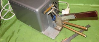
Microelectric Voltage Generated Machine
The tachometer generator converts the shaft rotation indicator into an electrical signal. Its operation uses the properties of the angular velocity of the rotor, the excitation flow, which is proportional to the generated EMF. Most modern tachogenerators are the permanent magnet type. These devices use a rotating joint, one end of which is connected to the machine shaft, inducing an electromotive force (voltage) proportional to the speed of the shaft. The armature contacts are connected to the voltmeter circuit, converting the voltage into a speed value.
These tachometers are distinguished by their accuracy, maximum permissible performance and operating temperature. Used as sensors in various automotive and electromechanical computer devices. Operate in AC or DC networks.
Another homemade tachometer
In order to measure the number of revolutions, as we already know, counting the pulses of the breaker or the voltage from the spark plugs is used. The frequency of these pulses is linearly related to the motor speed. You can also try to organize an inductive coupling with such a circuit, which will be demonstrated in this device. The basis for this option is a single-vibrator labeled LM 555.
Operating principle of a car meter
The tachometer is used to check the performance of the engine and helps the auto mechanic understand its condition to optimize operation within acceptable parameters. The operating principle of a car electronic tachometer is simple. The ignition system triggers a voltage pulse in the electromechanical part of the tachometer, which responds to the average voltage of the pulses in proportion to the engine speed. The signal is transmitted by a double shielded cable to the indicator. Tachometers are temperature compensated to process measurements in the range of -20 to + 70 C ambient.
It allows the driver to select appropriate throttle and gear settings while driving, as long-term use at high speeds causes insufficient lubrication, affecting the engine, creating overheating and leading to unnecessary wear and tear and machine failure.
Checking engine speed
While operating a car, you need to know how to check the tachometer at home. Most cars are equipped with a speedometer, pressure gauge, coolant temperature sensor and tachometer. They are installed differently depending on the make and model of the car. Sequencing:
- Check the tachometer before driving, carefully inspect the sensors. The dial usually shows single or double digit numbers, which are limited by the red stripe of the permitted operating limit.
- Start the car. Press the brake pedal with your right foot and turn on the ignition key. The tachometer reading should rise before stopping at the engine idle speed.
- Press the gas pedal and pay attention to the behavior of the tachometer.
- Monitor the readings while driving in each gear and when switching to the next.
- Avoid excessive motor overload. The red line on the scale represents the highest number of revolutions the engine can safely handle.
- If you need to further measure the vehicle's RPM to help diagnose the problem, use a handheld tachometer that measures the RPM while running.
If the tachometer on a VAZ does not work
Usually, the lack of response from the arrow is due to a broken contact in the connectors of the main wires of its connection, or damage to the wiring of the circuit. The first step is:
- Inspect the fastening of the conductor in brown insulation to terminal “K” on the ignition coil. If you detect poor contact, traces of oxidation, burning of a wire or terminal, fix the problem by cleaning the problem areas, treating them with anti-corrosion liquid, and tightening the fastening nut.
- Check the reliability of the connection of the black and white wire to the vehicle ground. If contact is broken, clean the wire and the surface to which it is attached.
- Using a tester, determine whether voltage is supplied to the red wire when the ignition is on. If there is no voltage, check the serviceability of fuse F-9, which is responsible for the integrity of the instrument panel circuit, as well as the condition of the ignition switch contacts.
- Disassemble the instrument panel and check the connections of the contacts in the tachometer wiring harness block. “Ring” all the wires going to the device with a tester.
DIY electronic tachometer
With the wide possibilities of the electronics market, it is not difficult to make a tachometer circuit at home using a multimeter. Moreover, the results obtained in such circuits are accurate in assessing the overall operating condition of the system being measured.
Circuit diagram using IC 555:
- The pulse is taken out from the scooter's spark plug and fed to the end of R6.
- The transistor responds to impulses in accordance with triggers.
- The transistor activates monostability with each incoming pulse.
- The monostable remains on for a certain moment, and when triggered, generates an average on-time output that is directly proportional to the average startup speed.
- The capacitor and resistor at the output of the IC combine the result so that it is directly read by a 10V voltmeter.
- R3 is adjusted so that the output generates an accurate interpretation of the RPM feed rate.
The above adjustment is made using a conventional tachometer. Parts for manufacturing are widely available and can be purchased at any radio supply store. List of parts for the homemade version:
- R1 = 4K7.
- R2 = 47E.
- R3 = 100 KB, may be variable.
- R4 = 3K3.
- R5 = 10K.
- R6 = 470 K.
- R7 = 1K.
- R8 = 10K.
- R9 = 100K.
- C1 = 47n.
- C2 = 100n.
- C3 = 100n.
- C4 = 33uF / 25V.
- T1 = BC547.
- IC1 = 555.
- M1 = 10V FSD meter.
- D2 = 1N4148.
- C5 with any value between 3.3uF and 4.7uF.
Before you make a tachometer with your own hands, you need to complete the installation documentation. A simple circuit designed using readily available elements with a rubberized MOC7811 opto-isolator module and two seven-segment displays measures disk speed in RPS. This circuit calculates RPS from 00 to 99; if larger values are needed, another decade counter is added.
The circuit diagram contains IC555, MOC 7811, IC CD4081, IC CD4069 and IC 4033 and a seven-segment LTS 543 display unit. On the first timer IC 555, configured as a monostable multivibrator, it generates a clock pulse when switch S2 is pressed, green LED 1 indicates the detection time .
Electrical circuit diagram
The presented tachometer circuit is distinguished by its simplicity and accessibility of parts for repetition due to the use of an integrated timer - the KR1006VI1 microcircuit (analogous to NE555).
The diagram consists of the following functional units. A pulse shaper made on VT1-VT2, a pulse width modulator on a DA1 chip of type KR1006VI1 and a resistor bridge on resistors R8-R13. An electrodynamic pointer microammeter is used to take readings. The disadvantages of the tachometer circuit include the need to balance the bridge for each type of milliammeter when repeating the circuit. But this is not a difficult operation.
The supply voltage to the tachometer circuit is supplied directly from the terminals of the car battery.