UAZ 469, 452, 3303 we repair the front wheel drive CV joint.
UAZ-469, 452, 3303
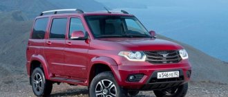
The main advantage of UAZs is all-wheel drive. For this, the owner is ready to forgive the car many shortcomings - high cross-country ability and simplicity of design make them tolerable.
But over time, when driving with the front end engaged, an ominous crunch appears, and the wheels slightly “bite” when cornering. The reason is most likely the wear of the CV joints. And it develops if there is longitudinal play in the hinge due to wear of the thrust rings. At the next TO-2, it is worth checking their condition. For this:
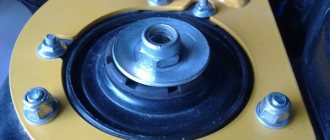
| Using a 14mm wrench, unscrew the six coupling nuts. | . and remove it. |
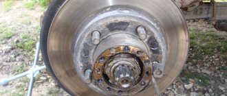
| Holding the splines of the drive, we move it towards and away from us. If you notice any play, the steering knuckle will have to be disassembled to replace the thrust washers of the hinge. | Unbend the lock washer. |
| ...and unscrew the nut. | Remove the lock washer. |
| Unscrew the second nut and remove the bearing thrust ring. | Remove the outer bearing and hub. |
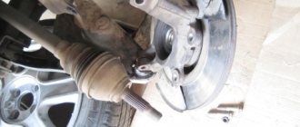
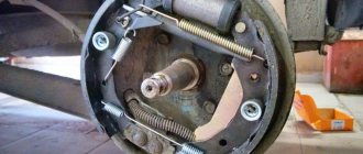
| Using a 17mm wrench, unscrew the six bolts securing the brake shield and axle. | We remove the boot... |
| ...and the brake assembly. And so as not to interfere, we put it on a spring. | We remove the trunnion. |
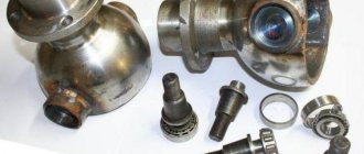
| We take out the drive and wash the parts in kerosene. |
Sometimes the hinge falls apart right in your hands. In order to make such a CV joint continue to work, it is necessary to eliminate the axial play and align the rotation axes of the hinge and the steering knuckle. When installing a new hinge, these conditions must also be observed, otherwise it will quickly fail.
| If the axle support washer is worn. | . we knock the puck out. |
| . remove the second support washer from the ball joint. |
We find the thickness C of the support washers using the formula: C = (B-A)/2, and their diameters correspond to the diameters of the sockets.
| Using a caliper, measure the distance A between the hinge support cheeks. We measure the distance B from the socket of the support washer to the end of the ball joint. |
Washers to compensate for play can be machined from steel (steel 45) and hardened. We press them into the axle and ball joint.
| Before assembly, fill the hinge cavity with “AM” or CV joint grease (about 500 g per hinge). |
We carry out assembly in reverse order. Having installed the axle and brake shield, we check whether there is any longitudinal play at the hinge and whether it rotates freely. Do not over-compress the joint. In this case, you need to remove the support washers and reduce their thickness.
Replacement of SHOPK ball joints Patriot
In our car service center, replacement of Patriot ball joints is carried out professionally and with a guarantee. All work, including repair of the UAZ Patriot steering control, is carried out by experienced craftsmen, of high quality and inexpensively. The price includes only work without spare parts and consumables.
| Automobile | UAZ Patriot |
| Category | 4x4 Tuning Removal and installation |
| Improve | Controllability |
| Car assembly | Steering |
| Periodicity | Upon breakdown |
Removing and installing the ball joint of the steering knuckle - SHOPK Patriot. Performed during repairs or to change the Castor angle of the king pins.
What is a ball joint for a steering knuckle - SHOPK
SHOPK Patriot, as its name implies, is located at the edges of the front axle beam and is attached to it with a bolted connection; it is designed to turn the wheels and control the direction of movement of the car. The steering knuckle is installed on the continuous front axle of trucks and all-wheel drive vehicles. SHOPK consists of a housing in which there is a constant velocity joint - CV joint. Also a component of the ball joint is a kingpin assembly - a kingpin, an oiler press, a steering knuckle lever, and a wheel rotation limiter bolt.
Operating principle of the steering knuckle ball joint
The work consists of turning the wheels using the steering knuckle lever connected to the steering rod. If there is a driven front axle, torque is transmitted through an axle shaft connected by a CV joint to the wheel hub. The main malfunctions of SHOPK are: - oil leaks; — grinding noise when turning the steering wheel; — wheel play; — steering instability; - “yaw” of the car along the road.
Reasons for replacing the steering knuckle ball joint
The causes of breakdowns of the steering knuckle units are the lack of high-quality lubrication of the steering knuckle and pivot assembly, high shock loads, especially when driving in off-road conditions. If there is a driven front axle, the cam mechanisms often break due to improper use of the vehicle. Namely, when connecting the front axle while driving, sharp acceleration with wheel slipping, driving with the front axle constantly engaged, or incorrect use of axle locks.
Repair of SHOPK steering knuckle ball joint
If there is play in the wheels, squeaking when turning, or rocking of the car when driving, you should immediately inspect and make the necessary repairs to the SHOPK units, since the correct operation of this unit ensures the safety of driving and controlling the car. Typically, the culprit of these problems is thinned kingpin liners. In addition, now on some cars they are plastic, which is why many motorists are replacing them with bronze ones. Repairing a ball joint or replacing a kingpin is much cheaper than subsequently replacing axle shafts, CV joints, and sometimes the steering knuckle body itself.
Navigation
Search
When operating the vehicle, pay special attention to the tightness of the pin sliding bearings. To control, you need to jack up the front wheel, grab the top and bottom of the wheel with your hands and shake it in the axial direction. If there is no play in the king pins of your car yet, it would be a good idea to fill the cavity of the ball joint with Litol 24 lubricant; better analogues of lubricant are also allowed, for example CV joint-4M. It would be nice to install a grease nipple on the pin to force periodic supply of lubricant to the friction zone, but to perform this operation properly, you will need to disassemble the entire assembly. We agree, when the speedometer shows only 10 thousand km. mileage, or a little more, doing this is not particularly pleasant. If you decide to perform this operation, do not forget to plug the hole in the hemispherical kingpin support. If there is play in the kingpins, repair is inevitable. Tightening the pins only gives the illusion that the fault has been eliminated and you can avoid looking at the unit for several thousand kilometers. The newly appeared play progresses very quickly and, as a rule, leads to failure of quite expensive mating parts, namely: a ball joint, axle, and sometimes a CV joint. Therefore, this is exactly the case when it is better to prevent a disease than to treat it. To carry out repairs you will need: a pivot wrench, a copper hammer or a soft metal mandrel, a caliper, an M 36*2 tap, an oil injection syringe, a set of keys, a torque wrench with a range of up to 30 kgf*m. Before starting repairs, it is necessary to produce spare parts - modernized kingpins, tin bronze kingpin inserts (set from Vaxoil). ATTENTION! On some vehicles, the right upper kingpin may have a longer threaded part. To determine, you need to look for the presence of a recess in the steering knuckle lever for the kingpin nut (Position 31. Figure 0). If there is a recess, the king pin is standard; if it is missing, you will need a long king pin.
So, the preparatory stage has been completed and you can proceed directly to the repair. The technology for installing a bronze liner and modernized kingpins is practically no different from that set out in the “Repair and Operation Manual for UAZ Hanter Vehicles and Its Modifications” (hereinafter referred to as OM), so below we provide only some explanations.
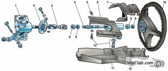
1 — wheel release clutch; 2, 9, 23 — gaskets; 3 - hub with brake disc; 4 — hub bearings; 5 — wheel mounting bolt; 6 - brake disc guard; 7 - axle; 8 — steering knuckle body; 10 — clamping bushing; 11 — kingpin; 12 — king pin insert; 13 - spring; 14 - outer sealing ring; 15 — internal sealing ring; 16 — hinge; 17 — ball joint; 18, 25 — thrust washers; 19 — kingpin support; 20 — outer race of the oil seal; 21 — overlay; 22 - nut; 24 - cuff; 26 — retaining rings; 27 — lock washer; 28 - nuts; 29 - lock washer Figure 1 - Steering knuckle and hub.
1. Manual, section “Disassembling the steering knuckle”, paragraph 6: “Use a special key to unscrew the clamping bushings 5 (the moment the bushing begins to rotate is 25-30 kgf*m).” Before starting the operation, it is necessary to strike the king pin along its axis with a copper hammer. Carefully monitor the guaranteed engagement of the spikes of the special wrench with the cutouts of the clamping sleeve (pos. 10, Fig. 1). Be careful not to damage the clamping sleeve and threads in the steering knuckle housing. 2. Operating manual, section “Front axle, maintenance”. clause 1. “Lubricate the conical surface and thread of the clamping sleeve, the rubbing surfaces of the king pin and liner with Litol 24 lubricant.” SHRUS-4M lubricant is preferable. paragraph 3 “Alternately increasing the torque by 2-3 kgf*m, tighten the clamping bushings with a final torque of 20-25 kgf*m.” When consistently increasing the torque of the clamping sleeve, each time through a soft mandrel, strike along the axis of the pins on both sides. clause 4. “Fill the cavities above the clamping bushings with LITOL 24 lubricant.” SHRUS-4M lubricant is preferable. clause 5. “Install the linings 21 (see Fig. 1) with gaskets 9 and tighten the nuts 22 with a torque of 8-10 kgf*m.” Tightening this nut allows you to adjust the turning torque of the ball joint. Pre-tighten these nuts to a torque of 5 kgf*m. The torque of rotation of the ball joint in any direction relative to the common axis of the pivot pins should be in the range of 1.0-1.5 kgf*m. Those. By holding the steering knuckle body with your hands, you should rotate it freely around the axis. If this does not happen, tighten nuts 22 on both sides until the desired result is achieved. Maximum tightening force 15 kgf*m. As a rule, if all of the above operations are performed correctly, the desired result is achieved the first time. 3. Manual, section “Assembling the front axle”. paragraph 3: “When installing the hinge, apply a thin layer of Litol 24 lubricant (anti-corrosion) to the internal cavity of the ball joint.” When performing this operation, we add about 500 grams of the same lubricant. Excess lubricant is forced out. The ball joint is pre-lubricated with CV joint grease - 4M. After running 1000 - 1500 km. it is necessary to check the preload of the pins, add a small amount of lubricant to the grease nipples, 2-3 guaranteed strokes with a syringe are enough, and if necessary, adjust the preload. The frequency of maintenance of the unit is 10 thousand km.
Blog about UAZ
It is not recommended to disassemble the constant velocity joint, constant velocity joint, front axle of vehicles of the UAZ-452 family unless absolutely necessary. If repairs are necessary, the CV joint must be disassembled and reassembled in a certain sequence.
Dismantling the CV joint of the front axle UAZ-452.
1. Mark with paint the relative positions of the hinge pins. 2. Open your fists. To do this, you need to knock with a short fist on the corner of a wooden stand. 3. Clamp the joint in a vice by the long fist with the short fist facing up. 4. Turn the short fist towards one of the peripheral balls. If the opposite ball does not come out of the grooves, you must press or hit the short fist with a copper hammer. In this case, care must be taken, since one of the balls can fly out of the hinge at high speed. 5. Remove the remaining joint balls. After selecting new repair balls of increased size or replacing one of the knuckles, assemble the hinge.
Assembling the CV joint of the front axle UAZ-452.
1. Clamp a long fist in a vice in a vertical position. 2. Insert the central ball. 3. Place a short fist on the central ball so that the marks marked with paint coincide and, turning it from side to side, install three peripheral balls in turn. 4. Spreading your fists 10-12 mm and turning the short fist to the maximum angle away from the free grooves, install the fourth ball so that it is clamped in the grooves. 5. Rotate the short fist to a vertical position. In this case, blows with a copper hammer on the rod of a short fist are allowed.
The preload in the hinge balls should be such that the moment required to rotate the fist 10-15 degrees in all directions from the vertical with another fist clamped in a vice would be equal to 300-600 kgfcm. The difference in the moments of rotation of the fist in two mutually perpendicular directions of one hinge should not exceed 100 kgfcm. To obtain the required preload and ensure proper assembly, the balls must be sorted into 9 groups.
Dimensions of diameters of CV joint drive balls, mm:
A - 25.32-25.34 B - 25.34-25.36 C - 25.36-25.38 D - 25.38-25.40 D - 25.40-25.42 E - 25.42 -25.44 F - 25.44-25.46 I - 25.46-25.48 K - 25.48-25.50
The diameter of the central ball is 26.988-0.05 mm. Each hinge must be assembled with balls of one group or two adjacent groups. For example, two balls with a diameter of 25.41 mm and two 25.43 mm. When installing, balls of the same size must be placed diametrically opposite. The difference in diameters of two pairs of balls of one joint is allowed no more than 0.04 mm.
After assembly, it is recommended to run the joint on a stand while changing the angle from 0 to 30 degrees for two minutes at a rotation speed of 300 rpm. When running in, the balls and grooves must be lubricated with oil.
Adjusting the tightening of the steering knuckle pins of the front axle of the UAZ-452.
When operating the vehicle, you should pay special attention to the tightness of the steering knuckle pins. At the factory, the pins are tightened with a preload, and the same number and thickness of shims are installed on the bottom and top. When the rubbing surfaces wear out, the preload disappears and an axial gap forms between the ends of the pins and the support rings of the ball joint.
This gap must be eliminated by removing the same number of shims from above and below. The difference between the total thicknesses of the upper and lower gaskets should not exceed 0.1 mm. To adjust you need:
1. Jack up the front axle. 2. Unscrew the fastening nuts and remove the wheel. 3. Unscrew the bolts securing the ball joint oil seal and move the oil seal away. 4. Move the steering knuckle body up and down with your hands and check for axial movement of the pins. 5. Unscrew the nuts of the studs securing the swing arm (left) or the bolts securing the upper lining (right) and remove the lever or the upper lining of the king pin. 6. Remove the 0.1 mm thin shim and install the lever or pin pad in place. 7. Unscrew the fastening bolts and remove the lower pin pad, taking out a thin 0.1 mm adjusting shim, and install the pin pad in place.
Check the build results. If the gap is not eliminated, re-adjust by removing thicker shims of 0.15 mm. The removed shims must be saved, since after several adjustments, only thick shims 0.4 mm thick may remain under the lever and pads, which will need to be replaced with several thin ones.
UAZ bridges
Many axle options were installed at the factory on UAZ vehicles of different models and at different times. Let's try to figure this out...
UAZ Timken bridge (civilian or collective farm)
This is a split type bridge, that is, a bridge consisting of two halves. A military bridge (also known as a gear or portal bridge) can also be classified as this type. From the factory, civilian axles are installed on UAZ trucks of the cargo range (loaf, flatbed, farmer), as well as on passenger cars of the UAZ-3151 (469) range.
Timken front civil axle for UAZ 469 and loaf cars
Rear axle Timken (civilian), for UAZ 469 and loaf cars
Photo of the gearbox of a half civil bridge
Photo of the Timken Civil Bridge tailpiece
The UAZ Hunter is equipped with so-called hybrid axles, with a stocking from conventional Timken axles and a steering knuckle from Spicer.
Gear ratios of the Timken bridge (civilian).
Until July 1989, civil axles were equipped with a main pair with a gear ratio of 5.125 (41 teeth), now - with a gear ratio of 4.625 (37 teeth), i.e., more “fast” but less “powerful”. You can find both in stores. You will most likely have to replace the “new” with the “old” main pair when installing very large wheels. It is recommended to replace the main pairs only as a complete set (in the front and rear axles), otherwise the front axle will have to be turned on only in mud, snow, sand, etc., so as not to damage the transfer case or spoil the tires. How to determine the gear ratio? You need to twist the cardan by hand and count the revolutions of the wheel. For example, 46 cardan revolutions - 10 wheels = 4.6 pair, etc.
Main pair for UAZ, Timken axles, hybrid, 37-8, 4.625
Weight of UAZ civil bridges:
- front axle - 132 kg
- rear axle - 100 kg
Geared (military) axles UAZ
Essentially this is the Timken Bridge, i.e. split, but it has a smaller central gearbox and has final drives. The factory installed military bridges on UAZ 469 vehicles for the army and UAZ, Bars. UAZ Bars bridges are military bridges, but with a wider gauge.
UAZ military bridges
Photos of UAZ military bridges
Photo of the UAZ final drive
Photo of the rear military bridge of the UAZ
Portal bridges UAZ Bars
UAZ Bars bridges installed on UAZ Bukhanka
Gear ratios of UAZ military bridges
The gear ratio of military axles is 5.38 (=2.77*1.94 - the gear ratios of the main and final drives, respectively) - more high-torque, but less high-speed than conventional axles.
Characteristics of a military bridge
- Ground clearance: 300 mm (with tires Ya-192 215/90 R15 (31 x 8.5 R15)
- Track: 1445 mm
- Gear axle track of UAZ Bars: 1600 mm
- Weight of the UAZ front military axle: 140 kg
- Weight of the UAZ rear military axle: 122 kg
Diagram of a UAZ gear (military) axle
UAZ rear axle with final drive:
1 – main gear housing cover; 2 – differential bearing; 3,13,49 – adjusting shims; 4 – sealing gasket; 5.7 – drive gear bearings; 6.15 – adjusting rings; 8.42 – cuffs; 9 – flange; 10 – nut; 11 – mud deflector; 12 – ring; 14 – spacer sleeve; 16 – main gear drive gear; 17 – satellite; 18 – right axle shaft; 19 – final drive housing; 20.29 – oil deflectors; 21 – axle bearing; 22,26,40 – retaining rings; 23 – sealing gasket of the final drive housing; 24 – final drive housing cover; 25 – bearing; 27 – brake shield; 28 – brake drum; 30 – wheel mounting bolt; 31 – axle; 32 – hub bearing; 33.41 – gaskets; 34 – lock washer; 35 – leading flange; 36 – hub bearing nut; 37 – lock washer; 38 – bushing; 39 – final drive driven shaft; 43 – driven shaft bearing; 44 – final drive driven gear; 45 – special nut; 46.50 – drain plugs; 47 – final drive drive gear; 48 – right cup of the satellite box; 51 – main gear housing; 52 – axle gear washer; 53 – axle gear; 54 – satellite axis; 55 – driven gear of the main gear; 56 – left cup of the satellite box; 57 – left axle shaft
Scheme of the UAZ rear military axle
Steering knuckle of the UAZ front axle with final drive:
a – signal groove; I – right steering knuckle; II – left steering knuckle; III – wheel release clutch (for an alternative design, see Fig. 180, IV); 1 – oil seal; 2 – ball joint; 3 – steering knuckle hinge; 4 – gasket; 5 – grease fitting; 6 – kingpin; 7 – overlay; 8 – steering knuckle body; 9 – pin bushing; 10 – bearing; 11 – driven shaft of final drive; 12 – hub; 13 – leading flange; 14 – coupling; 15 – locking ball; 16 – protective cap; 17 – coupling bolt; 18 – axle; 19 – lock nut; 20.23 – support washers; 21 – final drive drive gear; 22 – locking pin; 24 – rubber sealing ring; 25 – thrust washer; 26 – axle shaft casing; 27 – rotation limitation bolt; 28 – wheel rotation limiter; 29 – steering knuckle lever
Diagram of the steering knuckle of the front military axle with final drive
Replacing CV joints on a UAZ
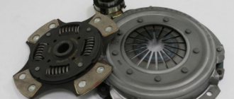
CV joint (constant velocity joint) is a transmission element of a UAZ and a number of other vehicles that ensures the same angular velocity of each wheel of the axle, regardless of how the car is moving. This structural part is used only on the front axle of both all-wheel drive and front-wheel drive units. This is due to the fact that the front wheels of the car turn, but the rear ones do not, so for the latter it is easier to use a relatively simplified differential.
A CV joint combined from two elements (axle shaft and balls) operates under conditions of constant friction and vibration, as a result of which, like any other mechanism, it fails. A faulty joint makes operating the car dangerous and extremely uncomfortable. Below you will learn how to diagnose a breakdown and replace the UAZ CV joint on different models of the brand.
UAZ CV joints in Balashikha
“One-click ordering” is available on the seller’s website. To go to the site, click “Go to store”
“One-click ordering” is available on the seller’s website. To go to the site, click “Go to store”
“One-click ordering” is available on the seller’s website. To go to the site, click “Go to store”
“One-click ordering” is available on the seller’s website. To go to the site, click “Go to store”
“One-click ordering” is available on the seller’s website. To go to the site, click “Go to store”
“One-click ordering” is available on the seller’s website. To go to the site, click “Go to store”
“One-click ordering” is available on the seller’s website. To go to the site, click “Go to store”
“One-click ordering” is available on the seller’s website. To go to the site, click “Go to store”
“One-click ordering” is available on the seller’s website. To go to the site, click “Go to store”
“One-click ordering” is available on the seller’s website. To go to the site, click “Go to store”
Popular products in stock! In the category: UAZ CV joints - buy at a good price, delivery: Balashikha, discounts!
Diagnosis of the malfunction and its causes
The CV joint, popularly called a “grenade” because of its appearance, has the following main causes of malfunction:
- defect or mechanical damage to the boot;
- factory defects (rare);
- aggressive driving style;
- lack of lubrication on the rubbing surfaces of the part.
The specific nature of the work is constant friction under load, which has an adverse effect on the condition of the part; therefore, if you want to increase the service life of CV joints, minimize the possibility of manifestation of the reasons mentioned above.
If the grenade breaks down, it needs to be replaced as soon as possible. It is often not necessary to carry out specific diagnostics of spare parts on UAZ vehicles; the malfunction manifests itself while the vehicle is moving with characteristic signs:
- crunching from the front axle and other crunch-like sounds, which manifest themselves especially strongly when cornering, during sharp acceleration or while driving off-road;
- When starting off, the car begins to move with characteristic roars.
If you still remove the CV joint from the car, then when you try to move it in different directions, the shaft moves freely. In addition to all this, a characteristic sign of a hinge malfunction is a violation of its integrity (the appearance of chips, crumbs, tears, etc.).
How does a faulty CV joint affect the performance of a UAZ?
The faulty drive begins to crunch when turning (with all-wheel drive connected); during intense acceleration, jerks are felt due to uneven transmission of power flow. Further operation leads to accelerated destruction of the drive and deterioration of vehicle controllability.
A faulty drive makes a crunching sound when turning.
Preparing for replacement
Before you start replacing, it is important to be prepared. First of all, buy a new one or new “grenades”, of which there are quite a lot in car stores, because breakdowns of CV joints on UAZs are not uncommon. During the purchasing process, the main thing is that the new part fully fits your car model.
Next, you need to prepare a standard set of tools for repair measures on the UAZ front axle, which includes:
- a set of spanners, socket wrenches and heads with a ratchet (extension);
- impact screwdriver;
- “hub” key - size 55 (less often than others);
- jack, block for wheels;
- lubricant, preferably both aerosol and creamy;
- hammer;
- rag.
The last stage of preparation for replacing the CV joint will be the correct installation of the car. It is done as follows:
- Place your UAZ over the inspection hole or lift it on a lift.
- In the first case, put the car on the handbrake and, for safety purposes, place supports in the form of a piece of wood under the rear wheels.
- If necessary, you can wash the working area of the suspension from dirt and conduct a more detailed inspection of the condition of the parts.
Determining the malfunction
CV joints are also popularly called “grenades”, which actually comes from the type of product. A CV joint malfunction can be caused by many reasons, which we will consider below:
- The main reason for the failure of the “grenade” is damage to the boot, which ultimately entails the penetration of aggressive environments into the working element of the product.
- If the part was made from low-quality materials, but this phenomenon is extremely rare.
- Aggressive handling of the car while driving.
- Lack of lubricants.
Thus, based on these reasons, the “grenade” malfunctions, which requires its immediate replacement. A CV joint is a kind of hinged product, the structure of which contains parts that work in close contact and under constant loads. As a result, any of the above factors leads to CV joint failure. It is not difficult to determine a CV joint failure. A characteristic sign of a malfunction of this product on the UAZ Patriot SUV is a crunching sound. This characteristic crunching sound comes from the balls moving along the groove due to the high degree of production.
UAZ PATRIOT: replacement of CV joints
In order to correctly replace the CV joint on a UAZ, you must have basic auto repair skills. It is advisable to carry out all repair work with protective equipment worn on the body against dirt, grease and other substances.
Replacing the UAZ PATRIOT CV joint is carried out as follows:
- Remove the two front wheels, and, if necessary, place a jack and other supports under the body.
- Remove the brake disc from the desired wheel and the ABS sensor.
- Unscrew the axle fasteners connecting it to the steering knuckle block. After releasing the axle, remove it along with the hub and coupling.
- Now you can start removing the axle shafts and the hinge itself. Regardless of the wheel, the CV joint is dismantled in the same way. Tap the desired “grenade” with a hammer and chisel and remove the part.
- Liberally lubricate the new CV joint and install it in the seat. Twist it for about a minute.
- Reassemble the entire mechanism in reverse order, periodically twisting the part in the seat.
Replacing the outer CV joint
An experienced car owner with practical skills will not encounter any problems when taking on the task of replacing the outer CV joint. The list of tools necessary to carry out the “operation” has already been presented above. In addition to tools and supplies, there are a few other things worth doing. Before removing the wheel, drain a little oil from the gearbox - this will make it easier to work with. You will also need a pry bar - it will serve as a lever when removing the drive shaft.
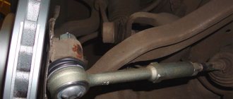
Let's assume that the problem is on the right. Replacing the right CV joint begins with removing the wheel. We unscrew the hub nut, remove the brake disc, caliper, ball joint and steering tip. We take a pry bar or crowbar and remove the splined drive shaft. Using light blows of a hammer (a support, such as a wooden block, will come in handy), we knock out the outer hinge. Next we perform the following steps:
- It is necessary to remove the hub nut and tear off the wheel bolts. We put stops under the rear wheels.
- We jack up the car, hang it up and then remove the wheel.
- Remove the bolts holding the steering knuckle to the ball joint.
- Turn the steering wheel all the way. Pulling back the steering knuckle, we pull out the outer half of the hub along with the old CV joint. If the grenade does not budge, hit it lightly with a hammer.
- We remove the old boot and clamps and throw them in the trash.
- We remove the CV joint with hammer blows, rotating it along the axle shaft.
- We fix the installed new hinges in the hub together with the boot.
UAZ 452 “Loaf”: replacing CV joints
Despite the general similarity in replacing “grenades” on all UAZs, “Loaf” very often causes some problems for motorists during such repairs. However, there is nothing to be afraid of, and anyone can carry out repairs. The entire process is discussed in detail below.
Replacing a CV joint on a UAZ “Bukhanka” requires the following actions:
- Also, on a previously prepared car, remove the front wheels.
- Using a socket or socket wrench set to “14”, unscrew the six nuts securing the coupling and remove it.
- Unbend the locking element (washer) with a special device.
- You have gained access to the CV joint fastening nut, unscrew it. Then remove the washer and, unscrewing the second nut, remove the bearing stop ring. Now you can remove the bearing and hub.
- The penultimate step before removing the “grenade” will be to dismantle all fasteners (there are 6) of the brake shield and axle using a “17” key.
- Next, you can remove the CV joint itself, also by tapping it with a hammer and chisel.
- Installation of a new one occurs in the same way as when replacing a “grenade” with a UAZ PATRIOT.
- Reassemble the entire mechanism in reverse order.
UAZ Patriot KochevniK › Logbook › Replacing the CV joint. We're all-wheel drive again!
Hi all.
As I wrote in the last entry, during the race we lost our front-wheel drive. I immediately realized that this was not RK, because... It didn't produce any sounds or errors. And the clicks came from the bridge. The right CV joint was torn. At first I tried to get through to a mechanic I knew for repairs, but “Tadpole” was stuck there for a long time. Well, I thought. Let's start mastering the skill of a mechanic! Before this I had a lot of cars, but I never repaired one myself, I always took it to a service center. And then I decided that, if possible, I wanted to work on this car myself. And so let's go. To replace the CV joint, we will need the following tools: 1. A set of heads. mostly 19 and 13. 2. Impact screwdriver. 3. Hub wrench 55 with 6 edges 4. Hammer 5. Jack and Support stand for safe repairs. 6. WD-40 It seems like I haven’t forgotten anything. Now the process itself. 1. Raise the desired side of the bridge with a jack and place it on a support post.
2. Remove the wheel. And turn the steering wheel to the right (or to the left for the other side) 3. Take a “ratchet” with an extension and a 19mm socket. Unscrew the caliper.
4. Next we will need a hammer and an impact screwdriver to remove the brake disc.
I unscrewed the disk, but it didn’t want to come off for a long time. Sprayed it with WD-40 and gently tapped it with a hammer. But only carefully so as not to damage the brake disc. 5. Now we need a hub wrench. Oh yes, the cover (I don’t know what it’s called correctly) I’ve already unscrewed the one that’s secured with 10 bolts. So we put the hub wrench on the hub nut. It won’t fit so easily; you need to carefully tap it with a hammer and put it on the nut and unscrew it.
There is a "circlip" behind this nut. We just take it out. Behind it is another similar nut. We also unscrew it and remove the hub.
6. Next we take the “ratchet” and the head. In my opinion, 15. I don’t remember exactly. And unscrew the bolts marked with red circles.
After unscrewing all the bolts, carefully tap with a hammer so that this “garbage” comes off. Sorry, but I don't know what it's called. I’m doing everything for the first time and couldn’t find any detailed information on the internet. They removed it and our CV joint right in front of us. If it is whole, then we simply take it out; if not, as in my case, we pick it out piece by piece. My CV joint fell apart. Axle shaft to diff separately, CV joint separately)))
I picked out all the scraps of the old CV joint. I cleaned and checked everything. Lubricated it with grease and inserted a new CV joint.
I filled everything with grease. And he began to assemble in reverse order. But there is a nuance when tightening the hub. It needs to be tightened until the play disappears. You can't over-tighten either! Then we install this retaining ring and lock everything with the second hub nut. In principle, that's all. I collected everything. He twisted it and pulled it out. we sit down, start it and ride))))
If you said or did something wrong, then sorry! I did everything first! There was no experience whatsoever. I couldn’t even really come up with a theory. I hope this report will be useful for people like me))) The price of the CV joint is 2400 rubles. And lubricant 110 rub. Thank you all for your attention! Good luck to all!
General algorithm of actions for replacing CV joints on all UAZs
Above, we considered the option of replacing CV joints on the two most popular UAZs in Russia and the CIS countries. It is worth noting that the principle of repair measures is similar for all models of this brand. So, for example, by analogy with the PATRIOT, you can replace it with the HUNTER. In any case, to avoid problems, below is a general algorithm for replacing CV joints on all UAZ models.
- Prepare the vehicle as described above.
- Remove the front wheels.
- Remove the brake disc (brake shield) and ABS sensor.
- Unscrew all the axle fasteners going to the steering knuckle.
- Remove the CV joints yourself.
- Install new parts.
- Reassemble the structure in reverse order.
When replacing, you must follow a number of recommendations:
- Lubricate new grenades generously before installation.
- The fastenings of the CV joint shaft are tightened strongly, but in no case with “overtightening”, otherwise the shaft will spin with a hook on the fastening and there is a risk of early failure of the new spare part.
- Before starting repairs, it is advisable to clean the suspension areas where the main work will be carried out from dirt.
- After installation, spin the wheel for a few minutes to lubricate “everything inside” and make sure that there is no play in the shaft. If there is one, you will have to redo the work.
As you can see, replacing a CV joint on a UAZ is quite simple. The main thing is to weigh your strengths wisely and follow the recommendations given above. Of course, you can’t do without some automotive repair skills, but you can’t do without them. Good luck on the roads!
Video on replacing a CV joint on a UAZ:
CV joints UAZ-3163 Patriot (with ground ball) (Ulyanovsk) set for axle
CV joints UAZ-3163 Patriot (with ground ball) (Ulyanovsk) set for axle
4 310
Dimensions (L x W x H):
0.95 x 0.12 x 0.1 m
No certificates found
Section under construction
Code: 000060287
53 pcs
4 269
Code: 000060291
Manufacturer: China
49 pcs
5 097
Code: 000110134
37 pcs
3 649
Code: 000110133
32 pcs
3 321
Code: 001511717
Manufacturer: PRAMO
3 850
Code: 001511713
Manufacturer: PRAMO
Why do you need a CV joint on a UAZ?
Reinforced type part
The drive mechanism of the driving front wheels is used on passenger cars with front-wheel drive, but it is also needed on all-wheel drive vehicles. This is due to the need to ensure equal angular velocities regardless of the vehicle’s trajectory.
This is why you need a constant velocity joint (CV joint). The design of the rear axle has a device such as a differential, which provides the ability to change the angular speed of non-steering wheels.
Which CV joint is better for the Patriot?
Because You are not logged in. To come in.
Because you are not a trust user. How to become a trustee.
Because The topic is archived.
Because You are not logged in. To come in.
Because you are not a trusted user (phone number is not verified). Enter and confirm your phone number. Read more about trusts.
Because The topic is archived.
Because You are not logged in. To come in.
Because you are not a trusted user (phone number is not verified). Enter and confirm your phone number. Read more about trusts.
Because The topic is archived.
Because You are not logged in. To come in.
Because you are not a trusted user (phone number is not verified). Enter and confirm your phone number. Read more about trusts.
Because The topic is archived.
Because You are not logged in. To come in.
Because you are not a trusted user (phone number is not verified). Enter and confirm your phone number. Read more about trusts.
Because The topic is archived.
Because You are not logged in. To come in.
Because you are not a trusted user (phone number is not verified). Enter and confirm your phone number. Read more about trusts.
Because The topic is archived.
Because You are not logged in. To come in.
Because you are not a trusted user (phone number is not verified). Enter and confirm your phone number. Read more about trusts.
Because The topic is archived.
Because You are not logged in. To come in.
Because you are not a trusted user (phone number is not verified). Enter and confirm your phone number. Read more about trusts.
Because The topic is archived.
Purpose and principle of operation
The history of the creation of constant velocity joints, including the UAZ CV joint, begins with the development of cardan drives. This transmission was created for a rear-wheel drive car and is represented by the following parts:
- drive shaft;
- driven shaft;
- intermediate shaft (if necessary);
- crosses (hinges);
- suspension supports (bearings).
The transmission of torque made it possible to transmit rotation over a certain distance, and some shift in the direction of rotation in the horizontal and vertical plane could occur. As a rule, the cardan drive worked in tandem with a differential, which changed the angular speed of rotation of the wheels. This design is called a unequal velocity joint; in this case, the driven shaft rotates with some deviation in speed relative to the drive shaft.
Location by car
The rotary joint is a mechanism consisting of two combined elements. This includes an axle shaft, one end of which is connected to the output shaft of the gearbox, and the second ends with a fist with cut longitudinal grooves. Along these grooves, balls inserted into the bowl, which is the beginning of the driven axle shaft, perform translational and rotational motion. Thus, rotation is transmitted to the wheel with a change in direction. Transmission is ensured without loss of rotation speed between the drive and driven shafts. The change in speed, taking into account the given trajectory, is still ensured by the differential located in the gearbox.
The difference between a cardan drive and the operation of a CV joint lies in the latter’s ability to transmit rotation at an angle of up to 70°, while with cardan shafts this angle is significantly lower. For high speeds, the deviation of the shafts from the common axis usually does not exceed 20°.
The design of the hinges is quite reliable and, with proper manufacturing quality, the part can function properly throughout the entire service life of the vehicle. However, under high loads that arise when the machine is actively used in difficult conditions, it becomes necessary to replace this unit. Malfunctions in the operation of the CV joint are also possible if the integrity of the protective cover is violated, when, as a result of a breakthrough, external contaminants begin to penetrate to the rubbing surfaces. Naturally, dust and sand not only impair the effectiveness of the special grease, but also destroy the surface of the interacting elements.
An emerging crunch in the CV joint of your UAZ vehicle forces you to resort to replacing the entire structure, since it is impossible to change only individual parts in this unit.
When further removing the CV joint from the axle shaft, you will need a hammer and a spacer. The main thing when striking is not to use excessive force. When struck correctly, the hinge easily comes out of its seat.
Possible faults
Despite the fact that the CV joint is the most reliable and durable unit in the entire car (its lifespan can significantly exceed the lifespan of any other part of the car under normal operating conditions), various problems often arise in it. Usually they are associated with a violation of the so-called normal operation mode, that is, with the ingress of water, dust or dirt into it. The hinge is protected from environmental influences by a protective cover - a boot, which is usually made of rubber or plastic.
The anthers are attached to the shaft using special fasteners - clamps. However, clamps for external CV joints are different from those used for water pipes. They look like this:
Also in the photo you can see a special device for tightening clamps and the principle of its operation.
So, the main malfunctions of the outer CV joint are associated, as a rule, with a violation of the integrity of the boot and the ingress of dirt and moisture into the CV joint. This leads to the formation of corrosion and increased wear tenfold. If you encounter such a problem, the severity of its consequences directly depends on how long you used the car with a damaged boot.
To repair the boot, you will need a rubber patch for car tires, sealant, and new clamps. The algorithm of actions when a violation of the integrity of the boot is detected is as follows:
- Clean the surface of the boot, degrease the area where you will stick the patch.
- Apply the patch to the boot according to the instructions.
- In order to ensure reliable tightness, fill the patch with sealant.
Important! This method is suitable for repairing only rubber boots, not plastic ones!
Another method of repairing the boot is more of a temporary measure that will allow you to get to a car service center or garage, where you will replace the boot or carry out a thorough repair (the first method). Its essence is to wrap the boot with a large amount of polyethylene and tape.
First of all, jack up the car, remove the wheel and clean the boot. Next, add lubricant to it using a syringe. Of course, the best option would be to remove the boot, wash the outer CV joint with kerosene, and pack it with new lubricant. But since we are considering a budget express method, we will be faithful to it in everything. Now take a plastic bag or film and carefully wrap it around the boot and nearby areas of the shaft. To make sure that the winding does not interfere with the normal operation of the shaft, rotate it in the direction of rotation of the wheel. Now all that remains is to wrap everything up with tape and hit the road, avoiding driving into holes, puddles or clearings with tall grass.
Advice! You can also squeeze out the old grease and replace it with new one. This will greatly increase the likelihood that no major failures will occur within the joint.
The process of repairing the boot using the second method is discussed in more detail in this video: