When operating a truck, various types of breakdowns are possible. How do you know if the clutch is broken? If the clutch fails, then it is not possible to operate the truck. It is the clutch that regulates the operation of the power plant.
In the event of a mechanism failure, it is necessary, first of all, to diagnose it and, subsequently, eliminate it. Let's look at the main breakdowns that may occur during the operation of a truck.
The clutch disc wears out no matter how the vehicle is used, so it is considered a consumable item. We must treat disk wear as a given; we must be prepared for the fact that it will have to be replaced. Of course, how long the clutch will last largely depends on the type of driving.
During normal operation, the clutch should be enough for at least 100 thousand mileage. This is the norm for trucks. It is advisable to change the clutch disc at a car service center, but you can replace it yourself. In this case, try using the recommendations in this article.
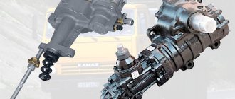
Adjusting the KAMAZ clutch: instructions
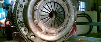
Reliability, excellent performance, efficiency - all this can be said about KAMAZ trucks. The machines are in demand for household, commercial and military purposes. The key to long-term and trouble-free operation is constant checking of the technical condition. Adjusting the KAMAZ clutch is always relevant. This brand is usually equipped with a dry double-disc or single-disc clutch (friction type). During its entire service life, the unit experiences enormous loads. Competent selection of spare parts and timely maintenance will guarantee long-term operation. Adjusting the KAMAZ clutch basket requires experience and certain knowledge.
Setting is necessary when:
- A crackling sound occurs when changing gears.
- Slipping at high speeds.
- Changing the free play of the clutch pedal (it has certain digital values).
If you ignore these signs, expect a serious accident!
KAMAZ clutch adjustment technology
Removing and adjusting the KAMAZ clutch is carried out in several steps.
Adjusting the free travel of the KAMAZ clutch pedal
The pedal must have a play of 6 to 12 mm. Measurements are taken from the central part of the plate. The pedal must be lowered until the main cylinder starts working. If there is a deviation from the norm, adjust the distance between the PSU pusher and the stop at the top.
To do this, you will need an eccentric pin connecting the pedal to the top eye of the pushrod. The pedal for traction must press the clutch pedal against the stop from above. The finger is turned so that the gap between the piston and the PSU pusher is in the range from 6 to 12 millimeters. When finished, tighten the castle nut securely. The full pedal travel should be approximately 19 centimeters.
Adjusting the KAMAZ clutch
The manufacturer recommends maintaining a free play value in the range from 3.2 to 4 millimeters. To measure, you will need to move the fork shaft lever by hand. It must move in the direction from the spherical nut of the pusher. It is located on the pneumatic or hydraulic clutch drive amplifier. Adjusting the KAMAZ clutch clearance will require removing the spring: the lever should move no more than five millimeters. If the free play is less than three millimeters, then it is adjusted using a spherical nut. The idle speed of the clutch must be from 3.2 to 4 millimeters.
Adjusting the KAMAZ clutch drive
To measure the function indicator, it is worth pressing the pedal all the way. If the value is less than 24 mm, then complete shutdown will not occur. It is necessary to measure the free play of the pedal and the volume of fluid in the master cylinder. 380 cubic centimeters is the total volume in the hydraulic drive. If the data does not satisfy the requests, it is important to get rid of air in the system. This will return all indicators to normal.
Adjusting the KAMAZ clutch pressure plate
During this operation, you must strictly follow the sequence:
- Initially, the gearbox is dismantled. You can't do it without helpers.
- Remove the clutch basket.
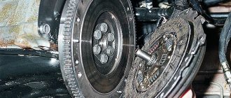
- The clutch discs are dismantled: first the driven one, then the middle one, and finally the driving one.
- New parts are being installed. The order is already reversed.
- It is important to adjust the nickel of the KAMAZ clutch basket.
- The correct installation of all mechanisms is checked in detail.
- The gearbox returns to its place.
If there is only one disc in the clutch design, the job is much easier!
But even a KAMAZ single-plate clutch, adjusting its parts will require serious skills, strength and knowledge. Don't take risks - entrust the matter to professionals. Or do a one-time replacement with a real mechanic. For some mechanics, adjusting the KAMAZ double-disc clutch without removing the gearbox is a reality.
Adjusting the legs of the KAMAZ clutch basket
The case is carried out in several steps:
- The checkpoint is dismantled. Use wrenches to unscrew the fastening bolts.
- Raise the box: it is better to do this with a cargo winch.
- Check the condition of the coupling, tension spring element, and release bearing.
- Unscrew the screws connecting the pressure plate and flywheel. To dismantle the pressure element, the driven disk must be supported.
- Carry out troubleshooting of all parts of the system (preferably).
- Check the condition of the release bearing. A working mechanism rotates easily, without unnecessary sounds.
- Conduct a visual inspection of the working surface of the pressure plate feet. After installing the new parts, the KS feet are adjusted. In this case, you will need a flat slab.
The location of the paws is oriented towards the working position of the pressure plate surface. Important : the operation does not require removing the joint from the additional flywheel. In this work you will need wrenches for the adjusting screws. The KS feet must be positioned so that the distance from the working plane of the pressure plate to the upper edges of the spherical protrusions on the inner surface of the feet is no more than 41 millimeters. But 40 mm is better.
To check the installation of the paws, you will need a special plate. The spherical protrusions must touch the control plate (it is installed on the hub). After completing the adjustment, all screws securing the support plates are tightened until they stop. Assembly proceeds in reverse order.
Source: https://gruzovik.biz/articles/regulirovka-scepleniya-kamaz-instrukciya
Clutch fails: what to do
Before the clutch failure occurred, you may have heard strange noises, the vehicle may have been moving jerkily, or the gears may have been shifting at intervals. Any breakdown is preceded by some events.
The car must be treated with due attention, then no breakdown will happen out of the blue. The driver often does not pay attention to the occurrence of extraneous sounds. This behavior can lead to serious damage and serious repair costs.
The clutch is broken: how to get to the service station
If the clutch refuses to perform its functions when the gear is engaged, then it is necessary to brake and move the box to the neutral position. If the clutch is still partially operational, you must change gears from fourth to first. In order to release the lever, you can rev the engine a little.
If the clutch fails, you need to turn off the ignition, put the transmission in first gear and turn it on again. The car will run jerkily, but then the speed will level out. This method can only be used when the engine is warm. To downshift, you need to shift the throttle.
In order to speed up and arrive at the service station as quickly as possible, you need to try to engage second gear. If the lever is in first gear, then you need to gradually increase the engine speed. Then you should reduce the gas by three quarters and put the lever in neutral.
The gas should be released completely, and only then engage the gear. It is strictly forbidden to change gear at high speed. When driving at a reduced speed, monitor the heating of the engine. At low speeds the temperature can be significant. This temperature regime can lead to jamming of the cylinder block.
Instructions for adjusting the clutch on KamAZ trucks
It is necessary to adjust the clutch on KamAZ 5320 and other models to maintain the good condition of the truck. Sometimes the need to carry out such work may arise on the road, so it is advisable for the car driver to know the basic conditions for independently and correctly setting up the mechanism.
The bulk of KamAZ trucks use a double-disc clutch with a radial arrangement of power springs. To operate the mechanism, a hydraulic drive with a pneumatic amplifier is used. Thanks to this design, the force required to press the clutch pedal is significantly reduced. During the operation of KamAZ, wear occurs on the clutch discs, which must be compensated for by adjustment. Correct adjustment of the mechanism ensures the fuel consumption declared by the factory and confident acceleration of an empty or loaded vehicle.
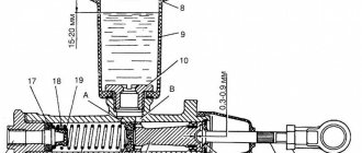
KamAZ clutch drive mechanism diagram
The main components of the drive, which is shown in the photo, are:
- pedal (1);
- hydraulic unit (2) with reservoir (3);
- highway (6);
- executive pneumatic cylinder (16).
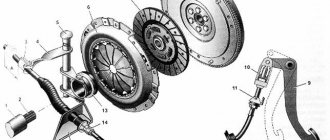
The KamAZ clutch of models 55111, 5320, as well as 43118 and 740 consists of the following structural units:
- clutch housing (A);
- release disc with stamped metal casing (B);
- pressure springs (B) and levers (D);
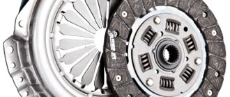
- one drive disk (E);
- two driven disks (D) with linings (W).
Clutch diagram for KamAZ 740 with diesel engine
The driven discs in the clutch design of a KamAZ truck are made using heat-resistant friction linings, which ensure a long service life of the mechanism. The design of the disks provides a damper for vibrations that occur when the motor shaft rotates. The drive pedal is mounted on special bushings and rarely requires lubrication during operation.
On more modern KamAZ models, single-disc clutches of the so-called Euro type are used. This mechanism is found, for example, on models 6520 or 4308. The supplier of elements for such units is Sachs, and amplifiers made by Wabco are used. There are several clutch models that differ in the amount of transmitted torque.
Assembly of parts and their replacement
Installing and replacing a double-disc clutch on a KAMAZ is a simple process. Common types of damage to the driven and pressure discs are cracks on their surfaces, on the linings, wear of the rings and linings, curvature of the disc, deterioration of the hub fastening, damage to the rivets, and scuffing on the disc surfaces. Replacing used gaskets with new ones requires removing old rivets. Disks that have become unusable also need to be replaced.
Not every car owner knows how to properly install clutch discs on a KAMAZ. There is a certain procedure.
The first of the driven disks is installed with the long end of its hub towards the motor, and the second - with the same end towards the gearbox. Before tightening the basket, the discs must be balanced.
As the linings on the driven disks wear out, as well as their replacement, the clutch drive should be adjusted, as well as the free play of the clutch.
Adjusting the clutch basket KAMAZ 740
Adjusting the clutch of KamAZ 5320, 43118 and other models consists of adjusting the position of the clutch, pedal, booster pusher and basket. The need for the procedure is checked by measuring the distance from the bottom of the pedal to the floor surface - the distance should be no more than 16 centimeters.
Design features of the clutch
Most KamAZ trucks use a double-disc clutch system (CC) with a radial position of power springs. To operate the mechanism, a special hydraulic drive equipped with a pneumatic amplifier is used. This scheme allows for a reduction in the effort required to depress the clutch pedal.
Clutch system diagram for KamAZ 4310 and 53215
Main elements of the device:
- Flywheel.
- Middle drive shaft.
- Driven pulley.
- Pressure disk.
- Crater device.
- Protective cover.
- Support fork.
- Gear shift lever.
- Deactivation clutch with bearing element.
- System shutdown plug.
- Thrust ring for shutdown levers.
- Release spring.
- A - play between the clutch bearing and the release lever ring.
Connection diagram for the clutch drive KamAZ 43118 and 65115
Main components of the circuit:
- Clutch pedal.
- Main cylinder.
- Cylindrical element of a pneumatic booster device.
- Pneumatic booster follower mechanism for a device with two discs.
- Air duct.
- Working hydraulic cylinder.
- Shut-off clutch equipped with a bearing element.
- Shift lever.
- Stock.
- Pipelines and pipes of the hydraulic drive.
Driven disks in SS KamAZ 55111 or 43114 are manufactured using heat-resistant friction linings, which prevent rapid wear of structural elements. The device also includes a vibration damper that occurs when the engine cranks. The pedal of the drive unit is located on special bushings and usually functions without the need for regular lubrication. More modern versions of KamAZ 55102 and 6520 use Euro class single-plate clutches.
Clutches in KamAZ systems may differ from each other in the amount of transmitted torque.
The main feature of the improved versions of the SS is the presence of a built-in indicator that determines the wear of the friction linings. The gap is measured by the distance between the body of the amplification device, as well as the washer located on the rod. In case of serious wear, this figure may be about 2.3-2.5 cm. In some SS for KamAZ 43114 and 4308 with a PGU, it may not be possible to adjust the position of the rod.
Preparing for adjustment
Before properly adjusting and bleeding the clutch on Kamaz 740, 5511 or other trucks, you must perform the following steps:
- Check the tightness of the drive device. To do this, you need to depress the clutch pedal several times. The presence of a serious air leak can be determined by hearing, and a weaker one can be determined by using a soap solution. If brake fluid is leaving the system, this can be determined visually. If problems are detected in the tightness, the components are tightened or the pipes are replaced.
- Carry out diagnostics of the fluid level in the expansion tank of the drive device. The volume of consumables should be about 15-20 mm below the edge of the tank neck. If required, the fluid level is replenished. It is not recommended to mix supplies from different manufacturers when performing this task.
- Check the operation of the pedal release springs, as well as the system release fork pulley lever.
- Tighten the bolts that secure the pneumatic reinforcement device CC. This procedure is performed using a torque wrench. The tightening torque should be about 90-100 Nm.
- Drain condensate, if any, from the pneumatic hydraulic booster.
Adjusting the clutch operation
To complete the task, you will need a special homemade product in the form of a piece of wire, one side of which should be 2 mm and bent at an angle of 90 degrees. The thickness of the rod is at least 3-4 mm. This size is optimal for controlling the gap between the tab outline and the disc release component. Adjustment is made using the nut of the pneumatic booster device. The legs must be brought to the ring through a hole located in the upper part of the crankcase.
You need to adjust the clutch like this:
- The locking screws are unscrewed with a wrench.
- The stoppers and plates are dismantled.
- Each nut is loosened and released 5 turns; for convenience, it is recommended to use a ratchet. If the penny protrudes beyond the surface of the ring, it must be recessed, checking in advance for the presence of ferodo at the bottom.
- When performing this task, you can also change the spring elements if they are worn out. The paws should be positioned so that they are in equal contact with the ring.
- The disk area runout is checked. If necessary, the bearing device is lubricated. The adjustment gap should be about 29-30 mm.
Adjusting the clutch pedal free play
According to the official regulations, the stroke for moving the pedal should be about 6-12 mm, and the measurement itself should be done from the central component of the plate. The pedal must be released until the main cylinder starts working after pressing it. Adjustment is carried out using an eccentric pin; when making adjustments, the pedal must be pressed against the upper stop. The castle nut is tightened as much as possible and the full stroke is replaced, which should be 185-195 mm.
Source: https://starifaeton.ru/info/regulirovka-korziny-sceplenija-kamaz-740/
Detailed instructions for adjusting the clutch on KamAZ trucks
Adjusting the clutch of KamAZ 5320, 43118 and other models consists of adjusting the position of the clutch, pedal, booster pusher and basket. The need for the procedure is checked by measuring the distance from the bottom of the pedal to the floor surface - the distance should be no more than 16 centimeters.
Most KamAZ trucks use a double-disc clutch system (CC) with a radial position of power springs. To operate the mechanism, a special hydraulic drive equipped with a pneumatic amplifier is used. This scheme allows for a reduction in the effort required to depress the clutch pedal.
Clutch system diagram for KamAZ 4310 and 53215
Main elements of the device:
- Flywheel.
- Middle drive shaft.
- Driven pulley.
- Pressure disk.
- Crater device.
- Protective cover.
- Support fork.
- Gear shift lever.
- Deactivation clutch with bearing element.
- System shutdown plug.
- Thrust ring for shutdown levers.
- Release spring.
- A - play between the clutch bearing and the release lever ring.
Connection diagram for the clutch drive KamAZ 43118 and 65115
Main components of the circuit:
- Clutch pedal.
- Main cylinder.
- Cylindrical element of a pneumatic booster device.
- Pneumatic booster follower mechanism for a device with two discs.
- Air duct.
- Working hydraulic cylinder.
- Shut-off clutch equipped with a bearing element.
- Shift lever.
- Stock.
- Pipelines and pipes of the hydraulic drive.