Troubleshooting in the OZS system
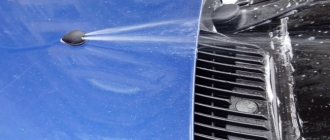
If you find signs that the rear window heating is not working, you must carefully check the entire electrical circuit of the vehicle's EOS system.
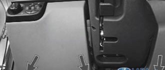
The first thing to check is the serviceability of the fuses. So, for example, on a VAZ-2110 these are rear window heating fuses F4 and F7, which are located in the mounting block. Their malfunction may occur due to a factory defect, short circuit or voltage surge in the on-board network. The faulty fuse needs to be replaced, for which it must be removed from the mounting block.
Next, you need to check the terminal connections in the OZS system. When operating a vehicle, all equipment is subject to strong vibrations. As a result, the contacts may be damaged or a terminal may become disconnected or loose.
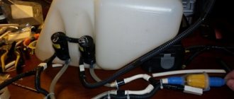
The heated rear window relay must also be checked. Breakdown of the relay is possible when the wire in the working coil of this part breaks or due to burnt contacts, due to a manufacturing defect or short circuit. To check it, the relay must be removed and checked using a tester. If this part malfunctions, it needs to be replaced with a working spare part.
You should also check the rear window heating contact. A conductive element is attached to the rear window using glue, which is a contact to which an electric current is supplied through a wire, which is transmitted through this contact to the heating filaments.
In this place, the wiring may break or, due to the fact that the glue was of poor quality, the contact element may peel off from the glass.
Quite often, the failure of the rear window heating is caused by a break or damage to the threads in the heating element on the rear window. This is detected by visual inspection or instrumental analysis. Visually, only obvious damage to the thread can be detected by identifying a gap between the damaged ends.
It is possible that during some repair work on the car, mechanical damage was caused to the surface of the glass on which the heating element is attached using glue.
However, the main tool for diagnosing this malfunction is a voltmeter or ohmmeter.
They allow you to accurately identify an area with faulty threads, even if this break cannot be visually detected.
How to find the location of a broken glass heating filament
It is not difficult to determine which heater thread is broken, since in the area where it passes, fogging does not disappear when the heater is operating. Therefore, in order to easily find the faulty thread during repairs, it is advisable to count the threads from top to bottom and remember which one is by number in the break, so that later, by visual inspection, try to find the place of its damage. But the thread break is so small that it is impossible to visually find it. Then a DC voltmeter, ohmmeter or voltage indicator will help in your search. To quickly find the location of a malfunction in a heating element, you need to understand how it works and works.
The design of the heating element of the glass heating system
The logical question is, why does it happen that only one or several threads in the heater do not work, while the rest work? To answer this question, you need to familiarize yourself with the design of the heating element.
The heating element of the rear window of a car is designed as follows. On the sides of the rear window there are two conductive busbars 1 and 2. Threads made of high-resistivity material are connected to these busbars. Each thread has a resistance of about 10 ohms. The number of threads depends on the height of the glass. Thus, each thread is a separate heating element, the operation of which does not depend on the others. A parallel connection scheme of heating elements is used. This circuit design ensures high operational reliability of the heater, since the break of one or more threads does not lead to a complete stop of its operation.
Finding a broken heater filament using a voltmeter
To work, you will need any DC voltmeter with a measurement limit of 15 V. Any pointer tester or digital multimeter will be suitable as a voltmeter. Before starting work, you need to turn on the heater.
Since one of the heating element busbars is connected to the car body, the negative terminal of the voltmeter can be connected to the car body; any screw or bolt screwed directly into the body will do. The most convenient way to connect to the trunk lid lock bracket is with an alligator clip.
Since it is difficult to visually determine whether the heater is heating with transparent glass, touching the positive probe of the voltmeter to bus 1, and then to bus 2, you will immediately understand this. There should be a voltage of +12 V on bus 1, and 0 V on bus 2. It is quite possible that the left bus in your car will be connected to ground, and the supply voltage will be supplied to the right bus. If there is no access to the tires, then measurements can be taken by touching with a probe any of the threads at the points of connection with the tires, that is, at the points where they exit the rubber seal. In the photo these are points 1 and 5.
Using a voltmeter it is easy to determine which part of the heating system is faulty. If the heater is turned on, the power indicator on the button lights up and there is 12 V on bus 1, but there is no heating, which means that the electrical wiring to bus 1 is working. If there is no voltage on bus 1, then there is a bad contact in the supply voltage terminal on bus 1, or the relay is faulty. If 12 V is present not only on bus 1, but also on bus 2, then you need to look for a bad contact in the terminal connecting the wire to bus 2 or the circuit connecting the wire to the vehicle ground.
Finding the location of the thread break
After checking the supply voltage supply system to the heater, you can begin to determine the location of the heating filament break. The thread is a tape resistance of about 10 ohms, and therefore the voltage at different points has different values. Therefore, at point 1 the voltage will be equal to 12 V, at point 3 - 6 V, and at point 5 - 0 V. Therefore, even without knowing which thread is broken, it can be easily found by measuring the voltage value at the midpoints of the length of all threads. On broken threads, the voltage will be 12 or 0 V. If the voltage is 12 V, then the break point is on the left, and if 0 V, then on the right.
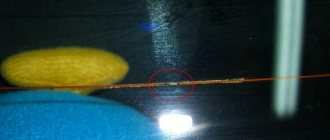
Now it is enough to slowly move the probe towards the break, in the place of a sharp change in voltage there will be a break. For example, in the photograph this is the section of thread between 6 and 7 points.
Symptoms of a malfunctioning rear window defroster
The heating system operates from the on-board electrical network. To quickly repair a car's rear window heater, you need to approximately understand the operating principle of the circuit elements and their structure. The diagram contains:
- switch;
- power switching relay;
- safety block (sometimes two);
- tapes or conductive threads.
The operation of the rear heater is extremely simple. After activating the ignition switch, the required voltage is transmitted from the battery through one (less often two) fuses to the relay block. After pressing the “heating” key, the contacts are connected, the current is transferred to the external winding of the relay and enters the heater filaments. Moisture from the rear window evaporates, revealing a full view.
A breakdown in any part of the circuit results in glass fogging occurring slowly or not at all. Depending on how quickly and efficiently the glass is cleaned, you can immediately understand where the failure occurred in the current supply circuit.
Heater doesn't work
The quality of the heater can be checked by turning the ignition key to the active position. On some cars produced before 2010, the heater starts working when the engine is running. This eliminates the rapid and excessive discharge of the battery, especially in those cars where there is an option for automatic engine warm-up, since the required current for the system to operate is 15-25 A.
The heater malfunction is checked by the button upon activation. If the "Heating" button light does not light up, the reason is a blown fuse. You can find the part in the diagram using the technical documentation for a specific car brand, if the unit was installed as standard.
The glass takes a long time to fog up
A typical reason when the rear window takes a long time to thaw is the insufficient heating of the filament. In total, a current of 10 A flows through the circuit, each thread receives a force of up to 1 A. If there is poor contact of any terminal or connector in the circuit, the power drops. The result is insufficient heating temperature of the conductive tape.
To check, use a voltmeter or tester. The tool checks the voltage parameter on the supply wire when leaving the battery.
Foggy streaks on the glass
One of the most common malfunctions in the operation of a winter heater is that the threads on the glass work fragmentarily. A non-fogged strip remains on the surface of the glass for a long time, blocking the view of the road.
The reason is a break in one or more conductive paths. Each thread has low strength and is easily removed with a hard brush, so it is forbidden to use finely abrasive products when washing - it is recommended to wipe the glass with a soft rag. In most cases, thread repair is carried out independently, using glue or conductive paste.
When the heated rear window fails for some reason and, as a result, it fogs up heavily or becomes covered with an icy crust, this greatly complicates visibility and leads to reduced safety on the road. To avoid this, it is necessary to eliminate possible breakdowns.
Scheme of work
- Voltage is supplied to the entire heating element, where the strips are connected in parallel.
- Because the metal strips conduct electricity and have some resistance, they become slightly warm. This temperature does not have a negative effect on the glass, but it can warm it up well.
- According to the methods of applying heating strips, electrochemical option, vacuum deposition or gluing can be used.
Chemical composition of the threads: resin, copper, graphite, nickel, chromium, tungsten. Manufacturers do not disseminate information about the manufacturing technology of the heating system, so you can restore its functionality by learning the striping technique. If spraying was used, it means that a carbon composition was used and conductive glue will be required for repairs.
Signs of breakdown
The main manifestations of why the rear window heating does not work include:
- complete shutdown of heating;
- Not all strips work;
- periodic performance of elements.
Experienced drivers will immediately notice when the heating is not performing its function sufficiently. In winter, the first sign of incorrect operation is fogged up windows when the heater is running for a long period of time. If the rear window heating refuses to turn on or functions intermittently, it means there is a break in the electrical circuit. All components of the heating device should be checked.
Old model VAZ 2107 fuse diagram
The “old” fuse box has 17 fuses. Each of them protects one or more electrical circuits. Purpose of fuses:
| Fuse number (rated current)* | Purpose of VAZ 2107 fuses |
| F1 (8A/10A) | Rear lights (reversing light). Reverse safety device. Heater electric motor. Heater fuse. Warning lamp and heated rear window relay (winding). Electric motor for rear window cleaner and washer (VAZ-21047) |
| F2 (8/10A) | Electric motors for wipers, windshield washers and headlights. Relay for wipers, windshield washers and headlights (contacts). Wiper fuse VAZ 2107 |
| F3/4 (8A/10A) | Reserve |
| F5 (16A/20A) | Rear window defroster heating element and its relay (contacts) |
| F6 (8A/10A) | Cigarette lighter fuse for VAZ 2107. Socket for portable lamp |
| F7 (16A/20A) | Sound signal. Radiator cooling fan electric motor. Fan fuse for VAZ 2107. |
| F8 (8A/10A) | Direction indicators in hazard warning mode. Switch and relay interrupter for direction indicators and hazard warning lights (in hazard warning mode) |
| F9 (8A/10A) | Fog lights. Generator voltage regulator G-222 (for car parts) |
| F10 (8A/10A) | Instrument cluster. Instrument panel fuse. Indicator lamp and battery charge relay. Direction indicators and corresponding warning lamps. Indicator lamps for fuel reserve, oil pressure, parking brake and brake fluid level. Voltmeter. Instruments of the carburetor electro-pneumatic valve control system. Parking brake warning light relay |
| F11 (8A/10A) | Brake light bulbs. Lamps for interior body lighting. Brake light fuse. |
| F12 (8A/10A) | High beam (right headlight). Headlight wiper relay activation coil |
| F13 (8A/10A) | High beam (left headlight) and high beam indicator lamp |
| F14 (8A/10A) | Side light (left headlight and right rear light). Indicator lamp for turning on the side light. License plate lights. Engine compartment lamp |
| F15 (8A/10A) | Side light (right headlight and left rear light). Instrument lighting lamp. Cigarette lighter lamp. Glove compartment lamp |
| F16 (8A/10A) | Low beam (right headlight). Headlight cleaner relay switching coil |
| F17 (8A/10A) | Low beam (left headlight) |
| * In the denominator for pin type fuses |
Fuse layout diagram for VAZ 2110, 2111, 2112
The photo shows fuses for VAZ 2110, 2111, 2112
As you can see, each fuse is numbered with a corresponding index. In the above illustration, the unit is located on the left side of the steering column and is integrated into the instrument panel. Below are the values of the specific fuse in this mounting block.
Table of fuse values for VAZ 2110, 2111, 2112.
| Fuse, no. | Current strength, Ampere | Values |
| F1 | 5 | Lamps for illuminating registration numbers, luggage compartment space, the entire left side of the vehicle's side lighting, as well as instrument lighting for dimensions and instruments. |
| F2 | 7,5 | Low beam left headlight |
| F3 | 10 | Left high beam |
| F4 | 10 | Front right fog lamp |
| F5 | 30 | Electric windows in doors |
| F6 | 15 | Cigarette lighter/lamp portable |
| F7 | 20 | Horn, engine radiator fan |
| F8 | 20 | Heated rear window |
| F9 | 20 | Windshield washer and wiper |
| F10 | 20 | Spare |
| F11 | 5 | Side light on the right side of the car |
| F12 | 7,5 | Low beam right headlight |
| F13 | 10 | High beam right headlight |
| F14 | 10 | Front left fog lamp |
| F15 | 20 | Heated seats |
| F16 | 10 | Left and right turn signals, hazard turn signals |
| F17 | 7,5 | Interior light, ignition switch illumination, brake lights, clock and computer illumination |
| F18 | 25 | Illumination of the glove compartment, heating controls, cigarette lighter |
| F19 | 10 | Reversing lamps, indication of instruments, computer, clock, serviceability of brake lights, door locking |
| F20 | 7,5 | Rear fog lights |
Removing and replacing the VAZ 2110, 2111 timing belt with your own hands
For clarity, the principle of parallel arrangement of some fuses is clear: F1-F3 are responsible for the electrics on the left side of the car, and those located opposite F11-F13 are responsible for the right side of the car. The rest are responsible for other vehicle functions.
Troubleshooting procedure
- Check fuses F8 (20A) and F8 (20A) (mounting block).
- We check the serviceability of the rear window heating button. Is there a “plus” on pin No. 10 of the switch button and after turning on the button on pin No. 9 (a test lamp or multimeter will be useful).
- We check +12V at the Ш5-2 output and at the connector near the rear window.
- We check the wires and their connections.
- We check the rear window heating relay - K7.
- We check the integrity of the glass heating filaments.
The algorithm for determining the cause of a malfunction is similar for most cars, the only differences are in the names of fuses, relays and connectors.
By the way, do you know that to extend the service life of the heating elements, they use a Glass Heating Regulator (DOC), and you can also install a Fresnel lens on the rear window?
Types, design and characteristics of rear window heating switches
All rear window heating switches are divided into two types according to design and operating principle:
- Key switches;
- Push-button switches.
Key switches are toggle switches in which the movable contact plate is moved using a key of one shape or another. To close the circuit, press one part of the key, and to open it, press the opposite part. Typically, two-position switches with an “On” position are used to control the defroster. and “Off,” but there are also three-position switches with a middle position and the ability to turn on various heater modes.
Push-button switches are switching devices with a button that is locked in a pressed (recessed) position. To close the circuit, press the button - it will sink into the body and lock in this position, providing current to the heater. To turn off the heating, press the button again - it will release and break the circuit. The buttons are only two-position - with the “On” positions. and "Off."
Keys and switch buttons can have a standard neutral design or be made for specific car models. Most often they are black, so they can be installed on various vehicles without disturbing the overall design of the dashboard. Therefore, today a standardized range of switches is used on both domestic and many foreign cars.
VAZ 2110 fuse and relay box
The electrical equipment is made according to the single-wire circuit of the VAZ 2110 mounting block: the negative terminals of the sources and consumers of electricity are connected to the “ground” - the body and main components of the car, which serve as the second wire. The on-board network is DC, with a rated voltage of 12 V. When the engine is not running, all consumers are powered by the battery, and after the engine is started, by an alternator with a built-in rectifier and voltage regulator. When the generator is running, the battery is charged.
Most electrical circuits are protected by fuses. Electric motors of gear motors - wipers of the windshield, rear window (VAZ 2111, 2112), headlights (if installed) - are protected by automatic reusable bimetallic fuses. The power supply circuit of the fuel injection system (VAZ 2111, 2112 engines) is protected by a fuse-link made of wire with a conductor of reduced cross-section (1 mm 2 ). The circuits for charging the battery, ignition (VAZ 2110 engine), starting the engine, “generator - ignition switch - mounting block” are not protected. Powerful consumers (headlights, cooling system fan motor, electric fuel pump, etc.) are connected via a relay.
VAZ 2110 fuse box diagram
Location of the VAZ 2110 relay: K1 - lamp health monitoring relay, K2 - windshield wiper relay VAZ 2110, K3 - turn indicator and hazard warning relay, K4 - headlight low beam relay, K5 - headlight high beam relay, K6 - additional relay, K7 - rear window heating relay, K8 - backup relay, F1 - F20 - fuses.
Most of the fuses and relays of the VAZ 2110 are located in the mounting block located in the car interior to the left and above the pedal assembly. The rated current of the fuses and the circuits they protect are indicated in the table. If the mounting block fails, it is possible to replace the printed circuit board or solder wires to replace the burned-out current-carrying tracks.
Electrical diagram of connections of the mounting block VAZ 2110 relays and fuses
The outer number in the designation of the wire tip is the number of the block, the inner number is the conventional number of the plug, K1 - K8 is the relay.
To switch the main circuits of the car, a combined ignition switch is used, consisting of a contact part and a mechanical anti-theft device.
On VAZ 2110 cars with engines 2111 and 2112, there is a fuel injection system wiring harness that is installed instead of the 2110 engine ignition system harness. The VAZ 2110 injection system relays and fuses are located near the controller, under the instrument panel console on the right.
Repair work
The filament can literally be “painted” using conductive varnish or a special repair kit.
If this does not help, you may need to install a new relay.
It is located either in the standard relay box or in the passenger compartment fuse box. Installation is simple: take out the old one, put in the new one. But before this procedure, you must disconnect the battery!
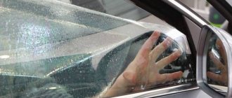
Heated rear window is useful not only in winter, when you can’t see anything on the glass due to ice and snow, but also in summer, when it rains and the glass fogs up. The malfunction of this option causes a number of inconveniences and makes the train less safe, because visibility is significantly reduced. Let's look at the reasons why the heated rear window of a car does not work.
How to repair a heated rear window of a car with your own hands
Heated rear window is actually a mandatory option, as it allows you to get a high-quality view, which is necessary for the safest operation of the car.
Heating is necessary both in summer (removing moisture from foggy windows) and in winter (it becomes possible to quickly melt ice and snow on the glass). The heating itself consists of special conductive tracks (rear window heating threads) applied to the glass from the interior side. At first glance, the solution is simple and reliable, but this is not entirely true. Unfortunately, during the operation of the car, for one reason or another, repair of the heated rear window may be required. Next, we will look at how to find the cause of the problem and troubleshoot.
Rear window heating problems
Over time, your vehicle may experience some problems with the rear window defroster relay. There is a problem with the heated rear window and side mirrors, the fuse has melted. This means it needs repairs. Such problems can arise due to a loose fit of the brush to the glass due to the driver axis being stuck in the bushing; add lubricant.
If the pad sits too tightly in the caliper frame, then you need to install new pads that move freely. There will just be a loud knocking sound when driving on uneven roads. Transmission noise will remain at the same level.
For VAZ cars, the rear window heating relay is designed for a certain time - about fifteen minutes. This system works thanks to a built-in timer.
On vehicles that are equipped with a heating relay, such a system can be installed in a standard relay and fuse box. A new one is installed in place of the standard relay and the heating is turned on with a standard button.
In addition, it is important that the relay coil is constantly connected to ground. The relay turns off the heating when the engine is not running
This is especially important because the battery does not drain.
Lada 2114 Kvarts › Logbook › Time relay for heated rear window ENERGOMASH 361.3787-02
Having gotten used to good things... (on Nexia)...I decided to install a heated rear window with automatic shut-off and a non-latching button - “press and forget”...after surfing the Internet I came across the website ENERGOMASH 12v.ru
Rear window heating time relay ENERGOMASH 361.3787-02 Designed to turn on the rear window heating for a fixed time when voltage is applied to the relay “winding”. It is used on VAZ 2104-2115, Niva, Priora, Kalina, AZLK 2141 and other cars, which provide for the installation of a rear window heating relay (type 90.3747-10) in the standard relay and fuse block and the relay is controlled by a plus. Relay 361.3787-02 is available with a built-in timer and has the ability to manually adjust the operating time (1-30 min). Adjustment is carried out using a tuning multi-turn resistor through a hole in the relay housing. An LED is provided to diagnose the operation. Convenient visual control of the time setting is ensured thanks to the transparent body of the product. The relay is supplied complete with a wire with a fuse tap.
1 Installation and connection 1.1 Install the relay in the relay and fuse block in place of the standard rear window heating relay (type 90.3747-10) or mini-relay (type 98.3747-10) using an adapter. 1.2 Connect the wire with the fuse tap coming out of the relay housing to the vehicle’s on-board network. To do this, remove one of the standard fuses, on which a “+” appears after turning on the ignition (for example, the power fuse for the turn relay in maneuvering mode), insert it into the free (lower) connector of the coupler, and install the fuse coupler in place of the removed fuse.
2 Recommendations for operation The relay is ready for operation after turning on the ignition. The relay operation is controlled by the standard button for turning on the heated rear window. 2.1 Turn on the glass heating and start the timer by pressing the button. Forced shutdown of heating is carried out by pressing the button again, as well as after turning off the ignition. 2.2 The heating is turned on again: 2.2.1 By pressing a button - when using a non-locking button. 2.2.2 By releasing the button and pressing it again - when using a button with a lock. The operating time is adjusted before the relay is turned on.
Source
The procedure for repairing a faulty OZS system
Having determined the reason why the rear window heating does not work, you can begin to repair this system.
- If the fuses or relays of the OSZ system are faulty, then the faulty parts must be removed. Replacing them with new, functional ones is not difficult. The main thing is that they are installed as indicated by the on-board electrical system diagram.
- In the case where the culprit of the damage in the OZS system is the terminal connection, restoring the heated rear window is also not difficult. It is enough to clean the contacts in the terminals. The terminal box may need to be replaced, but this will not take much time either.
- If the glue that was used to attach the contact on the rear window turned out to be of poor quality and peeling occurred, then in this case you need to buy a new high-quality conductive glue. Remove the layer of old glue from the peeled contact using a napkin with an alcohol solution. Then apply a layer of new connector and glue the contact in place.
- If a wire is torn off on one of the buses, it is necessary to solder this wire to the old place using the connection diagram. The procedure is as follows:
- remove the remnants of old solder from the wire, stripping the end; in addition, you need to clean the connection point on the bus;
- Using a brush, apply rosin paste as a flux to the cleaned surfaces of the bus and wire;
- Apply solder containing three percent silver to the cleaned and rosin-coated wire core;
- solder the wire to the bus, while avoiding overheating of the surfaces.
- The greatest care when repairing the heated rear window with your own hands is required if a break is detected in the conductive threads of the heating element of the OZS. To make this work easier, special repair kits for this system are available. To correct the damage, perform the following steps:
- in the area of the rupture, clean an area six millimeters long in each direction from the damage site;
- wipe the cleaned area with a napkin or cloth soaked in alcohol or an alcohol solution;
- On both sides of the damaged thread, stick thin strips of repair adhesive tape or ordinary construction tape, if there is no repair kit. Avoid sticking adhesive tape onto nearby threads to avoid damaging them;
- if there is no repair kit, then the role of a special mixture will be played by glue, which conducts electricity well; it can be applied with a brush, being careful;
- after repairing the damage, you need to give time for the glue or special mixture to harden; you can use a hairdryer to speed up this process;
Phased renovation
The first thing you need to do is diagnose it and purchase a repair kit. There may be several options for a repair kit, and the repair technology in each case is discussed below.
Finding a Cliff
In addition to visual diagnostics of the condition of the threads, there are several more methods that are more reliable and effective:
- Visual diagnostics require activating the heater when the rear window is foggy. Where the threads are broken, the surface will warm up almost instantly, while in other areas visibility will be problematic.
- Using a voltmeter requires activating the ignition and then turning on the heating system. One probe should lie on the vehicle ground, and the second near the center of the heating tape. First wrap the second probe with foil. The break will be localized in the area where the voltage rises to 12 V or drops to zero. Ideally, this parameter should not exceed 5 V.
- The second method of using a voltmeter involves fixing one probe to the positive terminal of the heater, and the second one must be moved along the negative terminal strip. The problem area will be where the voltage is zero.
- Using the ohmmeter requires activation of the kilo mode. The device must be analog, with an arrow. The probes should be located near the system terminals, which are located in opposite directions from each other. Use distilled water to wet the cotton wool, which must be smoothly passed over the tape. As soon as the needle of the device moves, you will be able to detect the cliff area.
Repair with conductive glue
Repair of the rear window heating threads can be carried out using conductive adhesive. It is designed for temperatures from -60 to +100 degrees. You should not choose kits with glue, which cost 150-200 rubles. Often they do not last long or may not be effective at all. A cost of 300-400 rubles would be optimal for such a set.
Work order:
- Please read the instructions included with the kit. You should have a clear understanding of the options for applying the composition and the speed of its complete drying.
- Prepare the problem surface. Soak a rag in the alcohol solution and wipe the area.
- Lightly sand the edges in the break area with grade-grade sandpaper. It is enough to simply remove plaque and carbon deposits in two movements.
- Use tape to cover the strips along the thickness of the sides. It should not overlap the thread, but also avoid going too far away from the tape. Focus specifically on the width of the thread.
- Proceed to apply conductive glue to the prepared area using a brush or syringe. The instructions will tell you how many layers to apply. The overlap on the working areas of the tape should be 1 cm to the left and right.
- Remove the tape and wait until the composition dries completely. This will not happen before 24 hours.
- Check the functionality of the system after drying.
Alternative method
Traditional methods are also suitable for restoring threads. The only difference between them is the material used:
- Wood shavings combined with paint. The first material can be obtained from a bar of copper and brass, which must be processed with files. Choose a paint that matches the color of the heating tapes. Mix the ingredients in equal proportions until you reach the consistency of a soft dough. Use masking tape or tape to create a stencil. Paste the stencil and activate the heating. Contact can be determined by a characteristic hissing sound. Apply the mixture using a stencil. This method eliminates the need to wait a day. You can operate the car immediately after the manipulations.
- Soldering of the broken area is carried out using zinc chloride. Give preference to solder with a minimum tin content - POSS-4-6 or POS-18. A copper or silver core is suitable for repairing a large section of tape.
- The shavings can be used in combination with glue, which replaces the paint mentioned in the first method. A suitable option would be BF-2.
The procedure for repairing a faulty OZS system
Having determined the reason why the rear window heating does not work, you can begin to repair this system.
- If the fuses or relays of the OSZ system are faulty, then the faulty parts must be removed. Replacing them with new, functional ones is not difficult. The main thing is that they are installed as indicated by the on-board electrical system diagram.
- In the case where the culprit of the damage in the OZS system is the terminal connection, restoring the heated rear window is also not difficult. It is enough to clean the contacts in the terminals. The terminal box may need to be replaced, but this will not take much time either.
- If the glue that was used to attach the contact on the rear window turned out to be of poor quality and peeling occurred, then in this case you need to buy a new high-quality conductive glue. Remove the layer of old glue from the peeled contact using a napkin with an alcohol solution. Then apply a layer of new connector and glue the contact in place.
- If a wire is torn off on one of the buses, it is necessary to solder this wire to the old place using the connection diagram. The procedure is as follows:
- remove the remnants of old solder from the wire, stripping the end; in addition, you need to clean the connection point on the bus;
- Using a brush, apply rosin paste as a flux to the cleaned surfaces of the bus and wire;
- Apply solder containing three percent silver to the cleaned and rosin-coated wire core;
- solder the wire to the bus, while avoiding overheating of the surfaces.
- The greatest care when repairing the heated rear window with your own hands is required if a break is detected in the conductive threads of the heating element of the OZS. To make this work easier, special repair kits for this system are available. To correct the damage, perform the following steps:
- in the area of the rupture, clean an area six millimeters long in each direction from the damage site;
- wipe the cleaned area with a napkin or cloth soaked in alcohol or an alcohol solution;
- On both sides of the damaged thread, stick thin strips of repair adhesive tape or ordinary construction tape, if there is no repair kit. Avoid sticking adhesive tape onto nearby threads to avoid damaging them;
if you have a repair kit, mix the hardener with a silver-colored composition, which, after application, will act as a conductive thread. After mixing, apply this composition with a stick or brush to the damaged area, closing the circuit.
- if there is no repair kit, then the role of a special mixture will be played by glue, which conducts electricity well; it can be applied with a brush, being careful;
- after repairing the damage, you need to give time for the glue or special mixture to harden; you can use a hairdryer to speed up this process;
after the conductive strip has dried, you must carefully remove the self-adhesive tape; to do this, it is best to cut it with a knife at the junction of the thread being repaired, so as not to damage it when removing the tape;
After the work has been completed, you need to check the functionality of the OZS by starting the car engine and pressing the OZS power button.
Possible malfunctions with heated seats
The heating device must have a fuse. On the VAZ-2114, two such elements are responsible for the stable operation of the heating. One fuse is located in the mounting block (F16), the other is located under the dashboard.
If you notice that the control lamps do not light up when the heating is turned on, the problem most likely lies in the fuses.
Relay problems:
- The system is turned on in an electromagnetic relay, which is located under the dashboard.
- After the unit is triggered, check the voltage at terminal 87 with a multimeter.
- If operation does not occur, then you need to examine the relay winding at terminals 86 and 87 with an ohmmeter.
- If the problem lies in the relay, it needs to be replaced.
Another problem may be the usual lack of nutrition. To check this, do the following:
- It is necessary to check the power with the power off at the connectors under the seats.
- The black wire is the ground of the car, the second is the power supply, which should have 12 volts.
- Use an ohmmeter to check the resistance of the heater windings. As practice shows, the problem most often lies here. The windings burn or break.
Depending on the situation, the problem with heated seats can be solved independently. However, this requires disassembling the chairs.
To summarize the article, we note that we have not considered all the possible reasons why heated seats may not work. But using the information above, you will know which direction to go to identify the problem.
Methods for solving the problem
As can be seen from the reasons, the entire malfunction lies in the vehicle’s electrical system. In this case, many car enthusiasts go “where they’re not asked” and get additional damage. Therefore, if a motorist is not sure that he can cope or does not have sufficient knowledge to diagnose and fix problems, he must contact a professional auto electrician or a car service center.
Power button
First of all, you should check the heating on/off button. Historically, the Chevrolet Lacetti has a weak and vulnerable spot, especially on later models, so checking the element should be done first; besides, it can be easily removed.
Control board
One of the most difficult places to diagnose is the control or control board for the heated glass and air conditioner. Firstly, to get to this element you will have to disassemble the instrument console. Secondly, in order to carry out diagnostic operations, you need to have some experience in repairing radio equipment.
Having studied the forum and the stories of experienced car enthusiasts, we can come to the conclusion that cracks, microcracks, desoldering or other damage usually form on the board. If this type of failure is detected, there are two options: 1 - replace the element, 2 - resolder the board itself. Of course, the first option is better and recommended, since there is a 100% guarantee that the part is intact. In the second case, if you solder elements, you can either carry out the process incorrectly or miss something. But, nevertheless, most experienced car enthusiasts recommend contacting a car service to eliminate such breakdowns.
Wiring
Repeatedly, the reason for the sudden lack of heating of the rear window was the wiring, especially in the winter season. So, in order to carry out diagnostic operations you will need a multimeter. All diagnostics come down to a simple “ringing” of the wires and determining the area where the contact has broken. Of course, the manufacturer recommends replacing the wire completely to avoid a short circuit, but our car enthusiasts do it much easier: the wires are exposed, fastened together and insulated with nice electrical tape. Simple, cheap, cheerful.
Heating panel
The last main element is the heating panels. A broken filament in the support group can cause the entire system to short out and fail. A broken element will be immediately visible, so in this case, you will still have to contact a car service to fix the problem.
Fuse
A blown fuse caused by a short circuit causes the rear window defogger to stop working. To troubleshoot the problem, you need to find and look into the mounting block, and then remove the damaged element. Perhaps this is the easiest operation in repairing heated glass and other faults.
ECU
On new car models, the wiring ring can go into the electronic control unit, which controls all processes of the vehicle. So, the presence of errors or a minor malfunction can lead to the heated rear window no longer functioning.
To troubleshoot the problem, you will have to connect to the electronic control unit using a special OBD II automotive cable and diagnose the condition of the ECU. Usually, as practice shows, a simple error reset helps. At the same time, you can carry out diagnostic work on other vehicle systems.
What are the fuses in the Lada Priora mounting block responsible for?
So let's now go over the fuses:
- Fuse F1 is responsible for the electric radiator fan of the engine cooling system
- Fuse F2 is responsible for the heated rear window
- Fuse F3 is responsible for the high beam (starboard side)
- Fuse F4 is responsible for the high beam (left side)
- Fuse F5 is responsible for the sound signal
- Fuse F6 is responsible for the low beam (left side)
- Fuse F7 is responsible for the low beam (starboard side)
- Fuse F8 is responsible for the alarm signal
- Fuse F9 is responsible for the heater fan
- Fuse F10 is responsible for the instrument cluster, interior lighting, brake light
- Fuse F11 is responsible for the windshield wiper, heated rear window (control)
- Fuse F12 is responsible for output “15” devices
- Fuse F13 is responsible for the cigarette lighter
- Fuse F14 is responsible for the side light (left side)
- Fuse F15 is responsible for the side light (right side)
- Fuse F16 is responsible for terminal “15” of the ABS
- Fuse F17 is responsible for the left fog lamp
- Fuse F18 is responsible for the right fog lamp
- Fuse F19 is responsible for seat heating
- Fuse F20 is responsible for the immobilizer control unit
- Fuse F21 is responsible for the rear fog light
- Fuse F22 – F30 – reserve location for fuse
- Fuse F31 is responsible for the electrical package control unit
- Fuse F32 – reserve location for fuse
Electrical equipment that consumes a large current during operation is connected through relays that protect the switch contacts from burning. To replace relays and pin fuses, special plastic tweezers 1 and 2 are provided in the mounting block. A blown fuse is identified by a burnt-out jumper; if in doubt, you can check it with a tester.
Fuse boxes in the engine compartment
In the repair and operating instructions they are designated as mounting blocks (MB) A and C. The first includes fuse links SA1-SA7 for protecting high-current consumers. For the second - fuses No. 1-6. The purpose is given in the table.
Location of power inserts
Mounting block A
| Fuse number | Current strength, A | Protected circuit |
| SA1 | 150 | Generator |
| SA2 | – | Reserve |
| SA3 | 110 | Starter switch, light switch, steering column switches, fuel pump, low beam headlights, front side lights |
| SA4 | 50 | Electric power steering control unit |
| SA5 | 25 | ABS |
| SA6 | 30 | Radiator fan ECU |
| SA7 | – | Reserve |
Mounting block C
| Fuse number | Current strength, A | Protected circuit |
| 1 | 25 | ABC |
| 2 | 30 | Radiator cooling fan |
| 3 | 5 | Radiator fan ECU |
| 4 | 10 | ABS |
| 5 | 5 | Used electrical equipment |
| 6 | – | Reserve |
Protected circuits and fuse numbers in the VAZ 2106
The headlight, heater fan, interior light and similar faults do not work, it is worth starting to repair them by checking the reliability of the contact on the fuse protecting this circuit.
So, let's start, the photo below shows a standard VAZ 2106 fuse box, numbering, as you can see, starts on the left side, from the driver's door. In VAZ 2106 older years of production, as well as in VAZ 2103, VAZ 2101, there is no additional fuse block. It is available in new models that have additional consumers - heated glass, electric cooling fan, etc.
Fuse box VAZ 2106
- Fuse No. 1 protects the horn, clock, brake lights, cigarette lighter, and front door open alarm circuits. Fuse rating is 16A.
- Fuse No. 2 protects the circuits of the windshield washer, windshield wipers, and heater motor. Fuse rating is 8A.
- Fuse No. 3 left high beam headlights, as well as the high beam indicator lamp in the speedometer (blue). Fuse rating is 8A.
- Fuse No. 4 protects the right high beam headlights. Fuse rating is 8A.
- Fuse No. 5 protects the left low beam headlights from short circuits. Nominal 8A.
- Fuse No. 6 protects the right low beam headlight circuit. Nominal 8A.
- No. 7 protects the trunk light circuit, instruments, license plate, cigarette lighter, left front side light and right rear side light. Nominal 8A.
- Fuse #8 protects the parking light circuit, license plate light, engine compartment light, right front side light, and left rear side light. Nominal 8A.
- Fuse No. 9 protects the tachometer circuit, the winding of the rear window heating relay, the reverse lamp, the glove compartment light, the battery charge warning lamp, the parking brake, the brake fluid level, the carburetor choke control, the oil pressure gauges, the coolant temperature and the fuel level, turn. Nominal 8A.
- Fuse No. 10 protects the battery charging circuit, namely the generator excitation circuit and the relay regulator. Nominal 8A.
- Fuses No. 11, 12,13 in the basic configuration are in reserve and can be used for additional equipment. The denomination is selected depending on the consumer.
- Fuse No. 14 protects the rear window heated element circuit, if installed. Nominal 16A.
- The protection circuit of fuse No. 15 contains an electric engine cooling fan, if one is installed in the vehicle. Nominal 16A
- Fuse No. 16 protects the turn signal and hazard warning light circuits. Nominal 8A.
Design of the rear window heating system
The system that helps clear the rear window of ice, snow or fog is not very complicated in design. The electrical circuit in general terms can be depicted as follows:
- C - generator.
- E230 - OZS system switch.
- J519 - on-board electrical network control unit.
- Z1 - heating element of the OZS system.
Although there may be some differences in different car models, nevertheless, if we consider it in detail, then in principle it includes the following main elements.
- Mounting block.
- Ignition switch.
- Heating switch ZS.
- Indicator lamp signaling the activation of the OZS.
- Heating element of the OZS system.
K6 - additional relay. K7 - OZS switching relay. A - connection to power systems.
In addition, the system has fuses, terminals and wires that connect all elements into a single whole.
When the ignition key is turned, the OZS is turned on by pressing a button, to which power is supplied through an additional relay K6. At the same time, the rear window heating relay K7 is activated, the heating element is connected and at the same time the control light comes on.
The design of the heating element on the rear window may also vary. In the standard version, it is a mesh of thin metal nickel threads, which are connected by two conductive busbars located on opposite sides. On one side, a 12V current is supplied to the bus, and on the other, the bus is shorted to ground. Such devices are attached to the glass using special glue.
On some car models, the heating element is applied to the glass using spraying, for example, aluminum. A thin film with good light transmission is attached on top of this coating using glue that conducts current.
Checking the rear window heater on Lanos
For a quality check, we need a multimeter or, as a last resort, a 12-volt test lamp with leads
How to check the heating element on glass
To do this, use a multimeter or a test lamp. First, carefully inspect the conductive strips. It is quite possible that, due to carelessness, one of them was damaged and the supply of voltage to the heater stopped. In any case, press the button to turn on the heater and measure the voltage on the bus on the left side of the car. If everything is fine with the wiring, 12 V should be supplied to the bus. If there is voltage, but the heating element is dead, the problem is in the threads. We look for a break and restore the heater. We'll figure out how to fix the heating element a little later.