Computer diagnostics of cars: basic steps
To perform diagnostics, first start your tablet or laptop, and then connect the adapter or extended cable connecting the tester to the connector. It is necessary if the operation is carried out using a desktop computer to the appropriate output. After this, you just need to take a few simple steps:
- turn the key in the ignition to turn on the power. This is necessary, since otherwise the software will not be able to receive a signal from the controller and display error codes on the computer display;
- we launch the software on a tablet or laptop. If you made no mistakes when connecting and use only working equipment, a diagram of the entire electronic part of the car will appear on the display;
- We select the type of diagnostics we need from the menu (checking the engine, suspension, electrical equipment, gearbox, etc.) and start the process.
During diagnostics, the software will display only error codes detected by the on-board computer. To identify certain faults, you will need to decipher them. It’s not difficult to do, since you can easily find the meaning of all codes on any specialized website.
How to choose the right type of diagnostic work? We suggest focusing on the symptoms of a car malfunction. For example, if fuel consumption suddenly increases, you should check the engine, and if extraneous noise appears while driving, evaluate the serviceability of the vehicle’s chassis.
The route on-board computer (MBK or BC) has become an integral part of modern cars. It talks about how useful it can be, I don’t think it’s worth it, but here’s how to connect the on-board computer yourself. interests many. And also, is it possible to connect an additional on-board computer to the car?
There are many trip computers for the “ten” (State, Gamma, Multitronics, Orion, Prestige, etc.), and as a rule, instructions for the on-board computer that describe the connection process are included. But it’s not uncommon for us to receive a used bookmaker, without the documentation we need. Installing an on-board computer with your own hands is not difficult, because the necessary block for connecting the BC is already inside the dashboard. It is a 9-pin trapezoidal block. The best way to get to it is through the right dashboard window.
The pinout of the standard on-board computer connector is shown in the figure. Additional 10 and 11 contacts are not used on all BCs and are intended for connecting an external air temperature sensor. After we insert the block into the trip computer, all that remains is to connect the K-line.
Why is K-Line needed? It is through this wiring from the ECU that the most significant information for us is transmitted (error codes, internal combustion engine temperature, etc.). The K-line is located in the diagnostic block (which is used at service stations to diagnose a car) to the left of the steering wheel, not far from the gas pedal.
Our task is to connect the K-line to the on-board computer. that is, lay a separate wire from the BC block to this diagnostic block. Thus, the on-board computer will receive the information it needs and the diagnostic block will remain operational.
The VAZ 2110 diagnostic block, depending on the year of manufacture of the car, can be of two types: Euro-2 (GM) or Euro-3 (ODB-II). Where to find the K-line in the block is shown in the diagrams:
Second on-board computer in the car
It is possible to install an additional trip computer. A good example would be BC Sigma or State X1, which are installed instead of a small plug next to the SAUO block.
- Firstly, they do not have a high price (500-900 rubles);
- Secondly, they have only 3 contacts (“+12V”, “ground” and K-line), so connecting them as an alternative on-board computer is not at all difficult, the diagram is as follows:
- Thirdly, they do not take up space in the dashboard.
Thus, in our car there will be two on-board computers, one performs modest basic functions, and the second for diagnosing and setting ECU parameters. Digital errors on the on-board computer are easy to decipher.
Conclusion
It’s not difficult to install a bookmaker yourself; it’s much more difficult to decide on the choice of its model. We have already discussed where to buy and which on-board computer is better to choose in a separate article. In some models, it is also possible to install an external temperature sensor. By the way, on-board computers on the VAZ of the tenth family are available for old and new panels, but if you wish, you can install the BC for the new panel in the old one.
Diagnosis of VAZ yourself?! - It's simple!
In this article we will tell you how easy it is to carry out independent computer diagnostics, as well as related repairs of VAZ cars (2105, 2107, 2108, 2109, 2110, 2112, 2114, 2115, Priora, Kalina).
If your car has a check engine light or you are concerned about fuel consumption, read the article, we will teach you how to identify such hidden problems.
If your engine does not pull, there is a hesitation, or the car jerks, the problem may also be in the car's electronics or sensors. Also, you shouldn’t rush off the handle and run to a car service; perhaps the problem can be solved very simply, with minimal material costs. Read our article.
No car, especially a Russian-made car, is immune from malfunctions. The most unpleasant thing in this situation is if the problem is not obvious, such as faulty electronics or sensor. The first thought in such a situation is to immediately run to an auto electrician, let him solve these seemingly extremely complex problems. But! ... Is it worth overpaying that kind of money for a job that any car enthusiast can do at home, using a laptop or even using a mobile phone!? Every injection car, without exception, has a diagnostic connector; for VAZ cars after 2004 it looks like this (see photo). Most often, the connector is located under the steering column of the car.
In order to connect the car to the laptop you need a special adapter (see photo).
This adapter is inexpensive when compared with the cost of computer engine diagnostics at a car service center. You can order this adapter on the website www.diagnost7.ru.
The adapter fits all Russian cars without exception and even some foreign-made cars. Complete with the adapter, programs for car diagnostics are supplied.
What are the capabilities of the programs? What can you do with this adapter? Diagnostics: • Engine management system Bosch M1.5.4 (R83), Itelma VS5.1 (R83), January 5.1 (R83), Bosch M1.5.4 (Euro 2), Itelma VS5.1 (Euro 2), January 5.1 (Euro 2), January 7.2 (Euro 2), Bosch M7.9.7 (Euro 2), Bosch M7.9.7 (Euro 3/4), Itelma/Avtel M73, Bosch MP7.0 (Euro 2), Bosch MP7.0 (Euro 3), Bosch ME17.9.7 (Euro 3), Itelma M74, Itelma M75, Itelma M74CAN, Itelma M74CAN MAP • Automotive anti-theft system APS6, APS6.1 • Electrical package module EP Priora, EP Kalina NORMA, EP Kalina LUX, EP Granta, Granta/Priora instrument cluster • Electric power steering Mando (Korea), KEMZ, Autoelectronics, Aviaagregat, Sever/DAAZ • Autoliv ACU3 airbags (Kalina, Priora), Takata (Granta) • Anti-lock braking system Bosch 5.3, Bosch 8.0, Bosch 8.1, Bosch 9.0, Bosch 9.0 CAN • Heater/climate (Priora, Kalina, Granta) • Windshield wiper control unit (Priora) • Jatco AY-K3 automatic transmission
By connecting to the control unit (to the brains) of your Lada. You can evaluate the health of important car sensors, lambda probe (oxygen sensor), MAF (Mass Air Flow Sensor), etc. Video review of the k-line VAG adapter using the example of a VAZ 2110 2005. made for the website www.diagnost7.ru (here you can choose an adapter for your car):
Source
Pinout
Where is the diagnostic connector on the Lada Granta
? Knowledge of the pinout may be required if a car enthusiast wants to make an adapter for computer diagnostics with his own hands, or if you need to connect without it. Experts recommend buying ready-made devices without the need to make a plug yourself. However, if you do not have such an opportunity, and diagnostics need to be carried out urgently, we will consider two main pinout options used on VAZ cars of various years of manufacture. Until 2002, AvtoVAZ products used the following pinout option:
- The 4th and 5th pins are GND outputs.
- Pin 16 – +12 V (power line).
- The 7th contact is the diagnostic line itself.
Since 2002, the pinout scheme has changed significantly. Now it looks like this:
- Pin H – +12 V (power line).
- Contact G – +12 V for the fuel pump.
- Pin A – GND output.
- Contact M – diagnostic line.
There is one important note to note regarding this diagram. If you connect the connector without a block, but directly, it is recommended to use the charge from the cigarette lighter as a source of electricity
The peculiarity of this pinout is that contact H is not always routed in the car. The use of G is also not recommended because high frequency current is supplied. This can have a negative impact on the adapter, even to the point of burning it out. However, cases of burning out the fuel pump connector are quite rare. Therefore, if you wish, you can also use this option.
As you can see, the pinout on VAZ cars of different ages is sometimes very different. Therefore, we advise you to look at the registration certificate of your car and find out what year it is made. On older vehicles you will not find the new pinout design as it did not exist yet and on newer vehicles the old design was no longer used.
What is the diagnostic connector for?
Lada Priora in Perseus color: features of the model. Lada Priora colors
Knowing exactly where the diagnostic connector is located, car owners will be able to independently check the technical serviceability of their four-wheeled friend at any time and promptly replace failed components. You can begin such a check after activating the test program. With the help of the latter it is possible to solve the following problems:
- adjust the fuel supply;
- find the cause of the transmission malfunction;
- promptly identify problems with the ECU firmware.
In order to check the operation correctly, you need not only to know the location of the connector, but also the rules for using the diagnostic device. Therefore, before purchasing a testing element, experts recommend carefully studying its features in order to accurately understand the diagnostic results obtained and promptly eliminate any, even minor, malfunctions.
Location of the connector for connecting to diagnostic equipment
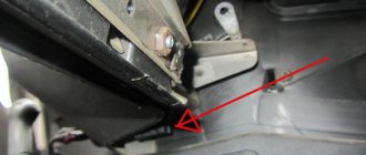
Finding the location of the connector with which the Lada Priora connects to diagnostic equipment is quite simple. This element is located immediately behind the car glove compartment, on the rear left wall. To be able to access the connector, you need to do the following:
- open the glove compartment;
- remove the glove box fastening clips;
- dismantle it.
The guideline for finding the location of the connector is the stove nozzle, which heats the passenger’s feet.
By drawing a conditional parallel line along the inside of the Lada Priora panel, you can see the element you are looking for, which is necessary for connecting to diagnostic equipment.
Priora diagnostic connector: where is it located and why is it needed?
The operation of the car control system is checked using special devices. Therefore, to test the vehicle, you need to find the Priora diagnostic connector and connect the equipment. The work takes minimal time. You just need to know the rules for connecting and using the test device.
For Lada Priora, the diagnostic connector allows you to test the ECU. The connection is completed in a matter of minutes. The connector is located near the glove compartment. You can get to it by looking under the recess for storing various small items.
Many motorists want to know where the Priora diagnostic connector is located and how to get to it. This will allow you to independently check the car. It is executed after the testing program is launched. Troubleshooting will help solve the following problems:
1. Incorrect measurement of oxygen in exhaust gases.
2. Incorrect fuel distribution.
3. Irregularities in transmission control (automatic and robotic gearboxes).
4. In difficult cases of Lada Priora, the diagnostic connector will indicate problems in the firmware of the ECU itself.
It is important not only to know where the diagnostic connector is on the Priora, but also to be able to use it correctly. Therefore, before purchasing a testing device, you should study the testing features. The results obtained will indicate any problems in the operation of the ECU.
You just need to be able to understand these problems and learn how to correct them correctly
The results obtained will indicate any problems in the operation of the ECU. You just need to be able to understand these problems and learn how to correct them correctly.
But knowing in Lada Priora where the diagnostic connector is located, you can not only repair the car. In some situations, such knowledge can lead to vehicle theft. Burglars use the connector to disable the alarm. There are several measures to solve the problem.
It is better to move the Lada Priora diagnostic connector to a new location at a service station. Specialists will do the work quickly and accurately. The driver can also perform the move. However, to do this you need to disconnect the wires from the connector and connect them to a new connector. The old one can be dismantled or left.
For the Lada Priora, the diagnostic connector, correctly installed in another location, will work properly and without interruption. And only the driver will know about the true position of the connector. You can place it near the steering column. It is very convenient to place the new connector near the gear shift knob.
Having no idea where the diagnostic connector is located in the Priora, attackers will not be able to carry out theft. And the car will work reliably and efficiently. Therefore, the connection diagram must be strictly observed during transfer. This will guarantee the normal functioning of the installation and the ECU.
To understand where the diagnostic connector on the Priora can be located during conversion, you need to study other AvtoVAZ models. Predecessors have a different connector location. Only design differences should be taken into account. The supply wires should not interfere with other car systems.
Where to look for the connector
It is important to know that on different cars the required socket is located in different parts of the car. Moreover, on some AvtoVAZ models it may be in a completely different place compared to another car
Let's look at several VAZ cars as an example:
- on the VAZ-2112, as well as on the 2110, as well as 2111, the socket is located to the right of the driver’s seat, immediately under the column;
- on models 2108, 2109 and 21099, the socket you need is located under the glove compartment, on a special shelf;
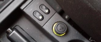
- on cars with a europanel it can be found in the center of the console, near the cigarette lighter. A special decorative cover is used to disguise it;
- on Lada Kalina cars, the connector can be found near the gear shift lever. As is the case with cars with a Europanel, it is hidden under a special cover;
- on a Priora you need to look for it right behind the glove compartment, on the wall.
We recommend: Why does the engine stall at idle? Possible causes and action plan
Why is a diagnostic connector needed in Priora?
Knowing where the special car diagnostic connector is located, each owner of a Lada Priora, without exception, is able to check the car for technical serviceability at any time convenient for him. This will allow you to timely replace the fault and replace failed components.
You can check the car after a special test program is activated, and with its help you can solve the following problems:
- Identify various types of problems that have arisen in the firmware of the electronic control unit.
- Determine the exact cause of the transmission unit malfunction.
- Adjust the fuel supply.
However, in order to carry out a correct test, it is not enough to know where the diagnostic connector is located; you also need to study the operating rules of the diagnostic device. And before buying a testing device, experts recommend that you carefully find out all the nuances in order to clearly understand what this or that result of the Lada Priora diagnostics means, in order to immediately eliminate all faults.
Do-it-yourself diagnostics
Various breakdowns of sensors and other devices can cause increased gasoline consumption, incorrect engine operation, and increased wear of car system components. Despite the presence of errors, the VAZ Priora will drive until the driver has to make expensive repairs because of them.
So that the motorist does not suddenly have to face the need for repairs, a special controller is installed on the VAZ Priora, with the help of which the driver can diagnose breakdowns. This can be done either using special additional equipment or an on-board computer installed in the car.
For example, you do not have a special tester, so we will look at diagnosing the vehicle for errors using the on-board computer. The BC is built into the dashboard and can be used to read combinations of faults. To do this, you need to activate the auto test mode.
What is it and features
The Lada Priora diagnostic connector makes a connection between the car’s control computer and a special diagnostic adapter or scanner. Manufacturers try to create their own connector in each car, but the functions remain unchanged:
- viewing and studying codes;
- determining the operating characteristics of the control system;
- cleaning diagnostic results;
- analysis of sensors with oxygen indicator;
- requests for diagnostic results while the vehicle is moving;
- control of actuators;
- View control indicators that were saved during fault codes.
What is needed for work
If you decide to diagnose faults in your VAZ 2110 yourself, then you will need several basic things for this work.
| Device | Peculiarities |
| Adapter | This is a kind of microcircuit enclosed in a housing. It allows you to connect the “brains” of your car with a computer and display the relevant information on the screen of a laptop or tablet. |
| Cable | Used to connect the adapter to the car and computer. Usually comes with an adapter |
| Computer | When choosing a computer, rely on what you have - a desktop PC, a tablet, a laptop. A laptop computer is better, since connecting a car to a stationary PC is difficult. Cables longer than 5 m are not suitable for diagnostics, so keep this in mind when connecting to a PC |
| Software | The necessary software can be found on the Internet, or you can take the software provided with the adapter. There are no problems with finding software today. |
When choosing an adapter and cable, take into account the characteristics of your vehicle. Not all adapters are universal
For the VAZ 2110, an example of an excellent adapter is the ELM327. We'll talk about it later.
How it works?
Now let’s figure out how it all works together and how you can diagnose the car yourself.
- The diagnostic program sends signals via the COM port through the adapter to the vehicle controller.
- The controller sends information in response.
- The program processes the received data, producing the corresponding result on your computer screen.
- Data exchange is carried out according to the appropriate protocol. Depending on the car manufacturer, the protocol may be different and have its own characteristics.
- To simplify diagnostics, many manufacturers use the universal ODB II protocol. Its capabilities are limited and not adapted for all cars. It is ideal for the VAZ 2110 model, since the top ten does not have an increased amount of electronics, unlike more modern cars.
- In the case of the VAZ 2110, the program on the computer screen will display the result in the form of error codes. It is enough to open the material where we described the error codes for the VAZ 2110 to understand what kind of breakdown has occurred to your car. Next, appropriate actions are taken to eliminate them.
https://youtube.com/watch?v=2RWzbHFrppk
A significant advantage of diagnostics is the fact that after it you know exactly what kind of malfunction you are dealing with. You don't have to go through half the car to find the source of the problem.
Types of diagnostics
Computer diagnostics of a car can be divided into three main types, one of which is not directly related to the VAZ 2110.
- Checking the suspension. It must be carried out if the rubber begins to wear unevenly or if extraneous sounds are heard when moving. Diagnostics will allow you to determine the reasons for the drift of the rear and front axles, which you may notice when entering turns at speed.
- Engine check. The main share of diagnostic activities falls on power units. The computer and adapter will help you if the idle speed is unstable, the car is difficult to start, fuel consumption increases, power decreases, etc.
- Automatic transmission check. Since the VAZ 2110 is not equipped with an automatic transmission, there is no point in diagnosing it.
Connectors
You have decided to carry out diagnostics. But what and where to connect?
On the VAZ 2110, the connector for computer diagnostics (CD) is located at the bottom of the steering column to the right of the driver. The connector is called OBD. This information makes finding the right adapter much easier.
To carry out the test, you should perform the following sequence of operations:
- An adapter is inserted into the OBD connector near the steering column;
- The computer must already be turned on;
- When the block is connected to the adapter, you need to turn on the ignition. Without power, the program will not be able to work and read data;
- Next, we connect the program with which testing is carried out;
- If all elements are operational, the car’s electronics will be displayed on the computer monitor;
- Start checking.
Pinout
Since for testing we need a diagnostic block, that is, OBD, it would not be amiss to learn about the features of its pinout. This way you can easily figure out how to connect:
- Contact A - is responsible for connecting the ground;
- Contact B - required to connect L-Line. Please note that not all vehicles have this contact;
- Contact M - used to connect K-Line;
- Contact H - power supply +12V;
- Contact G - controls the operation of the fuel pump.
Elm327 settings for Priora
Settings of the Torque Pro program for working with right-hand drive cars using the example of Toyota Mark II 2001 via ELM327
For right-hand drive Toyota Mark II (2001) Torque Pro, you need to write a command to programmatically reduce the speed of the ISO 14. and ISO 9. protocols (see the picture attached to the article)
For other models and brands of JDM (JDM-Japan Domestic MArket - Japanese domestic market), the following initialization lines should be entered to specify the protocol exchange rate:
Toyota Mark II 2001 y.o.: ATSP4\n ATIB96\n ATIIA13\n ATSH82 13 F0\n
Toyota Celica ZZT230: ATSH8213F1 \n ATIB96 \n ATIIA13
Toyota Vitz 01.2002: ATSH8213F1 \n ATIB96 \n ATIIA13, OBD2 protocol ISO 14230-4 (5b init, 10.4k baud)
Japan Domestic Market Nissan: ATSP5\nATAL\nATIB10\nATSH8110FC\nATST32\nATSW00
Japan Domestic Market Nadia/Harrier: ATIB96\nATIIA13\nATSH8213F1\nATSPA5\nATSW00
JDM Nadia/Harrier: ATIB96\nATIIA13\nATSH8213F1\nATSPA5\nATSW00
Toyota Common: baud rate - 10400 baud, ATIB10\nATIIA13\nATSH8013F1\nATSPA4\nATSW00
JDM Nissan(will test this with Xtrail): ATSP5\nATAL\nATIB10\nATSH8110FC\nATST32\nATSW00
Toyota Fielder: ATIB96\nATIIA13\nATSH8113F1\nATAL
JDM Toyota Caldina Gt-Four( 2004 model) Protocol: ISO 14230-4(5b init, 10.4k baud), ATIB96\nATIIA13\nATSH8113F1\nATSPA4\nATSW00
For the rest of the majority of right-handed Toyotas, it is enough to write the initialization line: ATSH8213F1\nATIB96\nATIIA13
Source
Where is the diagnostic connector on the Lada Kalina
The main purpose of the diagnostic connector (hereinafter referred to as DR) is to ensure the connection of the ECU, or electronic control unit, with an external reading device. This could be a laptop computer or a scanner. This allows Lada Kalina car owners to diagnose the on-board electrical system independently. A laptop or other device is connected to the DR via an adapter, after which a specialized program is launched that reads error codes from the control unit’s memory. And here a logical question appears: where to look for the diagnostic connector?
Diagnostic process using a laptop
We will not describe the diagnostic procedure for each software separately, since in general, regardless of the software, this process is identical.
The general diagnostic procedure is described below:
- First, you need to install the software on your computer. If you know how to use the Internet, then this step will not cause you any problems, since there is nothing complicated in its implementation. If your adapter comes with a disk with drivers, then they must also be installed, otherwise the computer simply will not recognize the device.
- Then you need to open the cover in front of the gearshift lever or remove the protective trim on the right side of the center console, depending on the version of the car. You should obtain and ensure unobstructed access to the K-Line output to which you will connect the laptop.
- Next, take the purchased cable and connect it - one side to the computer, the other to the output.
- After the cable is connected, you need to make sure that the computer recognizes it, to do this, check for connection. Alternatively, to do this, you can go to the Windows Task Manager and go to the Hardware tab. If the operating system recognizes the device, this information should be noted in this tab.
- If the connection is successful, then you need to run the test program on the laptop. After launching, the utility should ask you which components you want to diagnose (transmission, engine, etc.). If this does not happen, then navigate the menu - there should be a “Start diagnostics” button somewhere, perhaps in the File menu. All existing faults will be shown in the table in the form of error codes.
- If you go to the Parameters tab, you can see how the general condition of the vehicle is described here. In the Codes tab, all faults identified by the diagnostics should be noted.
- All you have to do is decipher the resulting combinations of numbers and start troubleshooting. As practice shows, quite often during testing, sensor malfunctions pop up - usually such problems are caused by broken wiring or poor connection of controllers. Therefore, if you encounter this, do not rush to change the sensors - try to clean the contacts on the connection connectors, and also check the integrity of the wiring.
- After the faults have been eliminated, you need to reset the control unit memory to remove all error codes from it. You can reset the unit's memory through the diagnostic program - usually this function can be found in the Management section.
The process of diagnosing a Lada Priora car using an on-board computer
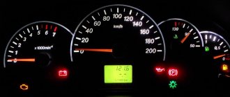
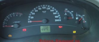
First of all, you need to know how to reset the parameters using the button to reset all daily mileage indicators. It is located on the instrument panel. You must press this button and, while continuing to hold it, you must simultaneously turn on the ignition using the key. Using these steps, you will be able to see all the error codes that have occurred and are available. Before displaying a list of error codes, the vehicle's autonomous self-diagnosis is enabled.
At this time, at the beginning of the diagnostic process, all arrows on sensors and instruments should show a jump from the minimum to the maximum indicator, at the same time at this moment all the necessary indicators and errors for checking the car should be shown on the liquid crystal display.
If at this moment any arrow does not show the correct movement or any position on the display does not appear, then you need to check the sensors and systems of the car for errors. Also, do not forget to check the display itself for faults, because A situation is possible when the car is working correctly, but errors are shown on the display solely due to the separation of any contacts.
Now, in the same mode of self-checking the car, you need to double-click any button that is responsible for switching the operating mode of the on-board computer. After these steps, certain numbers should appear on the on-board computer’s LCD screen. These are the Lada Priora error codes.
| Error code | Decoding |
| 2 | There is quite a strong voltage in the on-board control system. |
| 3 | Malfunction of the sensor, which is responsible for indicating the presence of fuel in the fuel tank. |
| 4 | Problems with the liquid that is responsible for cooling (its temperature readings may be inaccurate). |
| 5 | Failure in the system of sensors responsible for reading the air temperature outside the car |
| 6 | Engine overheating. |
| 7 | The oil pressure level will drop critically. |
| 8 | Problems in the braking system |
| 9 | The battery is dead. |
| E | There were malfunctions in the information package that was stored in the EEPROM |
An example of diagnostics using the ELM327 scanner
Below is an example of diagnosing a car with a scanner from AliExpress on version 1.5 using an Android phone and the OpenDiag application on a Lada Priora.
All manipulations with scanning the ECU must be carried out with the engine running or with the ignition on.
We connect the scanner to the OBD-2 connector and wait until the indicators blink.
Next, go to Settings/Bluetooth on your phone. There we find OBD II and pair it with it. When pairing, the device will request a password code - 1234, this code is the same for all scanners.
The next step is to go to the OpenDiag application. Click on the menu button, select the connection type and check the Bluetooth ELM box.
Next, click on the button in the upper right corner and select our device, in this case OBD II. After this the connection will occur.
The connection process is complete, then you can speed up the application itself and familiarize yourself with its functions.
Diagnostic example
Old and new VAZ-2112 diagnostic connector: pinout, where is it located?
Below is a diagnostic method using the ELM-327 device version 1.5 on a Lada Kalina car, through the OpenDiag program on the Android operating system.
Diagnostics must be carried out with the engine or ignition on.
We install the scanner into the diagnostic connector and wait for the lamps on the scanner to start blinking.
On your smartphone, go to settings in the Bluetooth section. In the available devices we find our scanner under the name OBD-II, connect to it. The device will ask for a password, enter the password – 1234.
After pairing with the scanner, open the OpenDiag program and click on the menu button, there we select the required connection type, in our case it is Bluetooth.
Click on the icon in the upper corner and select scanner from the list of devices.
The connection process is completed, the application itself will automatically detect the model and version of the ECU and display errors that are stored in the block.
Diagnostic connector type Priora
During the development of “injection” cars, various options for interrogating the ECU (electronic control unit) were developed. At first it was a system for reading codes using a warning lamp. Under special conditions different for different injection systems, the warning lamp began to flash. The master could only write down the rhythm on paper and, checking the table, determine the error.
Subsequently, special diagnostic devices were developed:
- Diagnostic adapters for personal computers.
- Automotive diagnostic scanners.
There are separate articles describing the operation of these devices. But they undoubtedly have one thing in common: a special connector is needed to connect the equipment with the ECU. At first these plugs were made different for each brand of car. There were both round and square. And just paired holes for the dipstick, like on VAG systems. But gradually manufacturers began to think about unification. So, by the early 2000s, the OBD-2 diagnostic connector, now so widespread, appeared.
OBD-2 connector design and its contacts
This connecting plug is made of plastic. The connecting part looks like a trapezoid (see photo). In total, it has 16 female contacts. The countdown starts from the top row, from left to right. The top row is considered to be the wide side of the trapezoid. The following sockets are used for the Priora car:
- Ground (ground), slots 4 and 5.
- Constant “+” 12 Volts - 16.
- Diagnostic socket - 7.
Typically, the equipment is connected to this connector through a special “plug”. The connector plug is of the same shape, but of the male type. Although those who work with various adapters can make connections directly. This is done on some types of adapters that have a separate probe for the K-line. You just need to remember that the “+” and “-” for the equipment must be taken from the battery of the vehicle being tested. Otherwise the communication signal will be incorrect.
Diagnostic connector location
In addition to the fact that these connectors had different shapes, they were located in different places. On the Priora, it is hidden very cleverly. Without knowing where exactly it is located, finding it is very problematic.
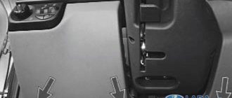
Don't let the fog in. The OBD-2 diagnostic connector on the Priora is located on the inner wall of the glove box on the passenger side. As they call it - the glove compartment. On the part that is adjacent to the “beard”. This is clearly visible in the photo. An experienced specialist, a master diagnostician, will connect with a standard connector by touch without any problems. Simply by opening the box and feeling for the nest behind its wall.
For novice diagnostic specialists, it is better to act according to the instructions. In order. That is, open the glove box completely. It will hang on the side plastic guides. Press these thrust plates a little, and the glove compartment will fold back further.
Carefully pull out the side tabs and release the glove box completely. Then access to the diagnostic input plug will be completely free. Well, then proceed according to the instructions for connecting the available equipment
Well, then proceed according to the instructions for connecting the available equipment.
Useful video about the location of the diagnostic connector on the Priora:
How to remove and check the sensor
Access from above to the Priora DD is difficult due to the intake module located above it. The easiest way to get to the sensor is from below, first removing the engine protection or at least unscrewing and folding its front part. When working from above, you will have to do everything by touch. In any case, before starting work, it is necessary to disconnect the ground wire attached to the “negative” terminal from the battery.
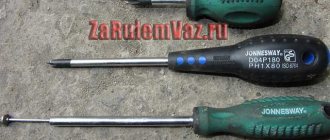
To remove the crankcase protection, you need to:
- unscrew 5 nuts with a 10mm head;
- unscrew the 2 19 nuts installed on the back of the shield;
- remove protection.
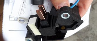
- by pressing the metal latch of the DD connector, disconnect the block of wires going to the controller;
- using a 13mm wrench, loosen the bolt securing the sensor;
- Unscrew the bolt and remove it from the threaded hole, removing the sensor.
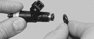
- We connect a multimeter to the DD terminals. We set the device to voltmeter mode, choosing a measurement limit of up to 200 mV.
- We take a metal object - pliers or a bolt - and lightly tap it on the DD.
When you tap on a working sensor, the voltmeter will show voltage surges. A faulty DD will not react in any way. A more accurate diagnosis of a removed sensor can only be done using a special stand.
Installation of a new DD is carried out in the reverse order of dismantling. Experts recommend installing a similar Bosch instead of the “native” one. Before going to the store for a new sensor, you should write down the markings of the removed sensor. Tightening the bolt securing it to 13 should be done with a slight force - 10.4–24.2 N m (1.1–2.5 kgf). Tightening too tightly will affect the operation of the sensor.
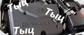
Problems with engine detonation can occur due to various faults. They are often associated with the operation of the electrical circuit from the knock sensor to the electronic control unit, or with the knock sensor itself. The diagnostic scanner can detect 4 common knock errors - P0325, P0326, P0327 and P0328. For the purposes of this article, we will look at error P0327, which indicates that a low signal level is coming from the knock sensor to the ECU.
Why is diagnostics needed?
Let's first figure out why we need to diagnose faults and whether this is required specifically for your car.
The main advantage of diagnostics is the ability to save money, time and modern nerves. If the car begins to behave inappropriately, some extraneous sounds appear, the stable operation of the engine is disrupted, then there are two options:
- To study all systems manually by dismantling and testing would waste a lot of time and nerves. The probability of finding the cause of the breakdown is far from 100%!
- Conduct computer diagnostics yourself by connecting a special adapter or cable to the computer. The program will scan the car and be able to issue the appropriate error codes. After studying our material with error codes, you can easily find the reason why the car began to behave abnormally.