We install an electronic instrument panel on a VAZ 2107
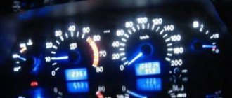
The control devices on the “seven” are concentrated in a single block and are highly informative.
For the VAZ 2107, in addition to the standard combination, an original electronic panel is produced, fully adapted for installation without altering the dashboard. There are several companies manufacturing products of this kind, and each of them offers its own version. On a VAZ 2107 model car, the so-called European control panel can be installed and connected with your own hands without the involvement of specialists. The delivery set contains all the necessary parts; to connect the device with the on-board network, standard connectors are mounted on its body. In addition, there is an installation manual and a technical passport, which contains a mark of sale by the store.
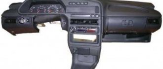
Removing the standard instrument cluster
Removing the factory panel from a VAZ 2107 is quite simple; it is installed in a niche on special brackets and secured to them with screws. The procedure for dismantling the equipment is as follows:
- We disconnect the battery by disconnecting the negative wire from the corresponding terminal of the battery.
- Using a flat-head screwdriver, remove the handles from the control levers of the interior ventilation and heating system.
- We unscrew the locking nut of the daily counter reset handle with a wrench and remove it together with the washer.
- We take out the plug for the screw securing the decorative panel and unscrew it.
- With a slight turn, we take the assembly out of the niche and gain access to the instrument cluster.
- By hand, unscrew the union nut securing the speedometer cable to the device and undock it.
- We remove the tube from the econometer fitting and disconnect three electrical connectors.
After this, the decorative panel with the instrument cluster is completely removed from the niche and you can work with it on the table. As can be seen from the description presented, dismantling this device on a VAZ 2107 car is not particularly difficult and can be done by a car enthusiast independently.
Tuning the instrument panel of VAZ 2107
VAZ-2105 wiring diagram (carburetor, injector) with description
Perhaps, everyone has a moment when the instrument panel in their VAZ car begins to seem dull and inconspicuous. In order to “revive” it, no expensive changes will be required, just make the backlight brighter and install a decorative sticker, which can be found in almost any car store, and replace the inserts on the dials. So, armed with a screwdriver and a soldering iron, we begin tuning the instrument panel of the VAZ 2107.
Removing the VAZ instrument panel.
The first step is to remove the sliders that control the operation of the heater (stove) using a flat-head screwdriver. Then, to the right of the emergency light button, unscrew and remove the nut and washer that secure the speedometer reset button. To the right of the removed sliders there is a small round plug that needs to be removed and the screw located behind it unscrewed. Then you need to carefully remove the instrument panel and release the speedometer cable by unscrewing the nut that tightens it. We disconnect all the wires, and the freed instrument panel remains in our hands.
The next step is removing the arrows
This must be done extremely carefully so as not to bend either the arrow or the pin on which it sits. It is quite possible that you will have to apply force, but carefully, pulling the arrow in a direction parallel to the pin. Instrument panel tuning
Tuning the instrument panel.
Before all work, align the speedometer needle with the limiter, and make a mark on the back side so that you know in which position the needle “lies.” This will greatly simplify the installation of the speedometer and eliminate unnecessary work.
First of all, we remove the old VAZ 2107 shields (this is done quite simply) and install new ones in their place. Then carefully install the arrows, again, so as not to bend the pins
In this case, it is important to align the marks on the back side of the speedometer and, with the marks aligned, set the arrow in the “lying” position. We also carefully apply the sticker you like, having previously degreased the surface. In this case, it is especially important to ensure that it lies flat and without distortion.
In this case, it is especially important to ensure that it lies flat and without distortions. Installing LED lighting
Installation of LED lighting.
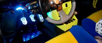
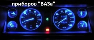
There are two options for installing LED backlighting on a VAZ - directly behind the scale numbers, or as a general backlight for the entire instrument panel. Naturally, all this remains at your discretion, the main thing to consider is that in the first case the backlight will be quite bright and you will have to spend quite a lot of time soldering and gluing the LEDs.
The LEDs should be designed for an operating voltage of 12 Volts, and it is best to increase their contacts by 2-3 cm. For the first option, we remove all the standard light bulbs and solder LEDs in their place. After this, connect the power (it is best to dim the light and adjust the position and direction of the LEDs).
For the second option, if you want to illuminate the entire panel, you can install either four LEDs located in twos at the top and bottom of the instrument panel (choose the distance yourself, it depends on which part of the instrument panel you want to illuminate more), or six - three up and down. In this case, you will need to solder additional wires to connect the LEDs to power and drill out the mounting points. One option is to glue the LEDs with glue if they do not coincide in location with the power points. In this case, it is recommended to use only good glue, and be sure to degrease the installation sites.
In addition, with this arrangement of LEDs, there is a little trick to increase the strength of the backlight. Along the inner perimeter, you can cover the side surface of the instrument panel with foil - it will reflect light from the walls inward, enhancing the backlight. To decide how much you need it, it is better to assemble the panel, connect the power and think carefully about whether the backlight of such power will suit you.
Assembling the VAZ 2107 dashboard is done in the reverse order, there is nothing complicated about it. The main thing is that you achieved the desired result!
Description of the electronic instrument cluster
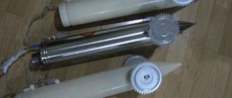
In our country there are several manufacturers of this type of equipment that offer their products to consumers. The electronic panel for the VAZ 2107 model car is a set of indicators and units of measuring devices, assembled in a single housing and adapted for installation instead of the factory one. This instrument combination contains the following elements:
- on-board computer with a liquid crystal display measuring 132x48 pixels;
- speedometer;
- tachometer;
- fuel level indicator;
- econometrician;
- turn signal indicators;
- indicator lamps for oil pressure in the lubrication system and battery charge level.
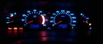
To make it easier for the driver to perceive information, the computerized dashboard for the VAZ 2107 car has a familiar appearance. The speedometer, tachometer and fuel level indicator are designed as dial indicators. This instrument combination has the following functionality:
- diagnostic tester;
- trip computer;
- alarm indicator;
- alarm clock and calendar;
- dynamic parameters indicator;
- storage and display of service book information.
After appropriate configuration, this instrument cluster will remind you of the need to perform vehicle maintenance operations. The information content of such a panel on a VAZ 2107 car is at a very high level, and well-chosen lighting does not distract from driving the car. The instrument cluster works on the principle of indicating only those parameters that have significant deviations from the specified ones.
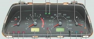
Pointer indicators
Pointer indicators are divided into two types: large (speedometer, tachometer) and small, depending on the diameter of the dial. They are located symmetrically on both sides of the indicator lights. Let's look at their purpose:
- The speedometer is the main indicator located on the right side of the dashboard. Shows the current speed at which the vehicle is moving. Has 10 divisions, from 0 to 180 km/h. Each division is equal to 20 km/h;
- Fuel level sensor - located to the right of the speedometer, on top. Indicates the amount of gasoline in the gas tank. Has yellow and green divisions. Removing the instrument panel and replacing the light bulb in it on a VAZ 2115 (2113, 2114). I installed the light bulbs without a base, without soldering them. If the arrow points to the yellow division, then there are less than five liters of fuel in the tank;
- Voltmeter - located under the fuel level sensor, and is used to determine the current strength in the vehicle system. It has 4 divisions, arranged in this order (from left to right) - red, yellow, green, red. If the arrow is on the left red division, then the charge level is low, if on yellow it is normal, on green it is excellent, and on the far right, also red, the current is too high;
- Tachometer – located to the left of the indicator lights. The problem of failure of the clutch fork in a VAZ 2107 car can be considered a disease of these car models. Indicates the number of revolutions of the crankshaft in 1 minute. Has 9 divisions, from 0 to 80 X 100 rpm. Each division is 1000 revolutions;
- Econometer - located to the left of the tachometer, on top. Indicates the most economical driving mode, depending on the current fuel consumption. There’s nothing on Tiida, just light bulbs on the feet and at least 1.5 times brighter. Which ones go where. It has 3 divisions, designated by colors: red, yellow, green, where red is increased consumption, yellow is moderate, and green, respectively, is minimum consumption;
- Coolant temperature sensor – located under the econometer. It indicates the temperature of antifreeze or antifreeze, and has 3 divisions. If the arrow points to a white line, it means the fluid temperature is low and the engine is not warmed up; if the arrow points to green, the temperature is normal, and the red line means the engine is overheating.
Compatibility of the electronic combination with the on-board network
The dashboard described above can be used on VAZ 2107 cars equipped with an injection system of various modifications. To connect the wiring harnesses, the developers used standard connectors that match the factory colors, which greatly simplifies the installation and switching of equipment. The geometric dimensions, shape and location of the mounting brackets are completely identical to the standard panel.
The equipment is adapted to work with electronic engine control units of January 5.1 and BOSCH M1.5.4 models. It is possible to reprogram the instrument cluster using an encoder with the latter connected through a special connector. The electronic europanel is compatible with parking sensors from the same manufacturer, information from which is displayed on the liquid crystal display.
Installation of this equipment on a vehicle using the included components:
- wiring harness;
- specially shaped connector;
- mounting bolts.
This dashboard was specially developed for the VAZ 2107 car as an electronic version and fits organically into the interior design. Automatic backlight adjustment makes the readings clearly visible and at the same time does not irritate the vision of the driver and passengers.
Location and diagram of power supply unit
The location of fuses for a VAZ 2107 with a carburetor or injector is the same. The mounting block with fusible inserts is located in the engine compartment on the right side in the direction of travel of the car. Fuse blocks were manufactured in two versions, old and new, and their choice also does not depend on the machine’s power system.
The description of the electrical equipment of carburetor and injection engines is somewhat different. This is due to the fact that the operation of the injector is controlled by the on-board computer.
Old style
Old style mounting blocks include 17 fuses and 6 electromagnetic relays. The number of the latter may be different, it depends on the vehicle configuration. Fuse links are installed in one row, have a cylindrical shape, and are held by spring-loaded contacts. Such a connection is unreliable, since the passage of large currents through the fuse leads to heating of the fuse links and spring contacts. In such a situation, deformation of the contact legs occurs, so you have to periodically remove the protective elements in order to bend or clean the oxidized contact.
Fuse links, electromagnetic relays and other components are mounted on two printed circuit boards, which are located one above the other and connected by jumpers. This design cannot be called successful, since it makes it difficult to repair the power supply. Difficulties may arise if you need to disconnect the boards, which not all drivers can do. This need arises, for example, when a printed circuit board track burns out. The problem occurs if you incorrectly replace the blown fuse element and install a fuse rated for a higher current.
Fuse box VAZ 2107
The wiring harnesses are connected to the power supply through connectors. In order to avoid mistakes when connecting, they have different colors. The rear part of the power supply protrudes into the glove box, where the connectors of the instrument panel and rear wiring harness are connected.
The VAZ 2107 fuse diagram can be seen in the figure below.
Fuse box diagram
The lower part of the power supply is located in the engine compartment, where there are also multi-colored connectors. To manufacture the power supply housing, plastic mass is used. Its cover is transparent and has the location of installation of relays and fuses and their rated current.
New sample
In the new type of fuse block, the fuse links have become blade-type, which increases the reliability of the power supply. If in the old configuration the fuses were located in one row, now they are installed in two rows. There is now only one printed circuit board inside the body of the new model, which has become easier to remove and repair.
New design block
The number of fuse links, as in the old block, is 17 pieces. 6 electromagnetic relays can also be installed, but in most designs of fuse blocks only 4 are used. Instead of other relays, jumpers are used.
Below is a video from user UidTrim about fuse pinouts.
Decoding
Let us consider in more detail the purpose and rating of fuse links for VAZ 2107 fuse blocks of two designs. For old-style devices, these fuses are designated by numbers from 1 to 17, and for new ones - by symbols from F1 to F17.
There is no separate protective element in the mounting block of the VAZ 2107 car, which is responsible for the radio. Most often it is connected to a watch or cigarette lighter.
Below is a breakdown of the relay in the VAZ 2107 mounting block.
Injector
The electrical circuit of models with an injector has an additional block of fuse links and relays, which is installed in the car interior under the glove box on the passenger side.
The pinout of this block will be as follows:
- F1 ensures the functionality of the main relay of the car; its rated current is 7.5 A.
- F2 is responsible for the operation of the electronic engine control unit, the current is 7.5 A.
- F3 is designed for a current of 15 A and ensures the operation of the fuel pump electric motor.
Three electromagnetic relays are also installed there:
- K1 - main relay;
- K2 - relay that turns on the electric fuel pump;
- K3 is a relay that turns on the fan motor in the cooling system of the power unit.
Pinout (connection diagram) of the VAZ 2107 dashboard
It so happened that in order to install the dashboard from the GAZ 3110 in my beloved VAZ 2105 (with a torpedo and wiring from the 2107), I needed a pinout of the instrument cluster from the VAZ 2107 . To my great surprise and horror, a search in Google and Yandex did not give a single clear result, the information is fragmentary and not always correct, so I decided to put everything together and write a small post-instruction for myself, in case it is useful to someone else