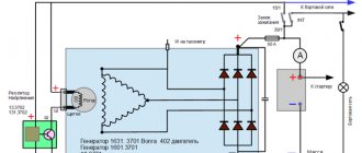
Ignition circuit diagram gas 3110 402 engine
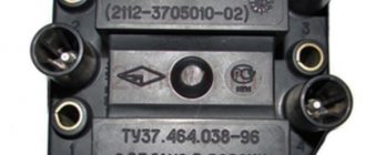
The ZMZ-402 and ZMZ-4021 engines are equipped with a non-contact ignition system consisting of a transistor switch, an ignition distributor of type 19.3706, an ignition coil of type B116 or B116-01, spark plugs and high-voltage and low-voltage wires.
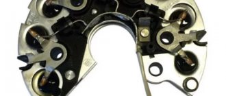
Ignition sensor-distributor (1908.3706) - non-contact, with sensor (generator) of control pulses and built-in vacuum and centrifugal ignition timing regulators.
The distribution sensor performs two functions: it sets the moment of sparking and distributes high voltage pulses among the cylinders in accordance with the order of their operation.
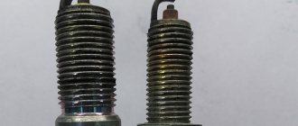
For this purpose, a slider mounted on the shaft of the sensor-distributor is used. An interference suppression resistor* is installed in the slider.
Instead of a resistor, part of the sensors has a cover with a central carbon contact.
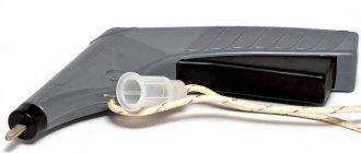
The switch (1313734) opens the power supply circuit of the primary winding of the ignition coil, converting the sensor control pulses into current pulses in the ignition coil.
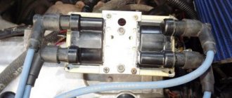
Ignition coil (engine ZMZ-402) GAZ 3110 Volga
- Repair manuals
- Repair manual for GAZ 3110 (Volga) 1996-2004.
- Ignition coil (ZMZ-402 engine)
7.10.2. Ignition coil (ZMZ-402 engine)
7.10.2.1. Removal
| EXECUTION ORDER |
↓ Comments ↓1.Operation and Maintenance 1.0 Operation and maintenance 1.1 Interior heating and ventilation 1.2. Running in the car 1.3 Checking the car before leaving 1.4 Frequency of replacing operating fluids and lubricants 1.5 Caring for the paintwork of the body 1.6 Frequency of lubrication of vehicle components 2. Engine 2.0 Engine 2.1. Removal and installation 2.2. Engine of models 402 and 4021 2.3. Lubrication system 2.4. Cooling system 2.5. Exhaust gas system 2.6. Engine power supply system ZMZ-4062 2.7. Power supply system for ZMZ-402 and ZMZ-4021 engines 3. Transmission 3.0 Transmission 3.1. Clutch with diaphragm spring 3.2. Clutch with peripheral springs 3.3. Five-speed gearbox 3.4. Four-speed gearbox 3.5. Cardan transmission 3.6. Rear axle 3.7. Axle shafts 3.8. main gear 4. Chassis 4.0 Chassis 4.2. Rear suspension 5. Steering 5.0 Steering 5.1. Steering wheel 5.2. Steering column 5.3. Steering mechanism 5.4. Steering linkage 5.5. Ball joints of the steering linkage 5.6. Pendulum arm 5.7. Ball joint of the pendulum arm 5.8. Power steering mechanism 5.9 Possible steering malfunctions. 6. Brake system 6.0 Brake system 6.1. Brake pedal 6.2. Vacuum booster 6.3. Main brake cylinder 6.4. Front brake mechanism 6.5. Rear brake mechanism 6.6. Pressure regulator 6.7. Parking brake 6.8 Bleeding the brake system 6.9 Possible malfunctions of the brake system. 7. Electrical equipment 7.0 Electrical equipment 7.1. Battery 7.2 Fuse block 7.3. Generator 7.4. Generator 9422.3701 or 2502.3771 7.5. Generator 1631.3701 or 192.3771 7.6. Voltage regulator 7.7. Starter 7.9. Sound signal 7.10. Ignition system 7.11 Electrical diagram of a GAZ-3110 car with a ZMZ-4062 engine 7.12 Electrical diagram of a GAZ-3110 car with a ZMZ-402 engine 8. Body 8.0 Body 8.1. Front buffer 8.2. Rear buffer 8.3. Radiator lining splash guard 8.4. Hood 8.5. Front fender 8.6. Trunk lid 8.7. Front door 8.8. Rear door 8.9 Replacing windshield and rear windows 8.10. External rear view mirror 8.11. Instrument panel 8.12. Windshield wiper 8.13. Front seat 8.14 Rear seat 8.15 Seat belts 8.16 Rear parcel shelf 8.17 Interior attachments 8.18. Heater 8.19 Possible malfunctions of components and body parts. 9. Applications 9.0 Applications 9.1 Weight of units 9.2 Lamps used on the vehicle 9.3 Rolling bearings used on the vehicle 9.4 Cuffs used on the vehicle 9.5 Fuels and lubricants and operating fluids 9.6 Tightening torques of critical threaded connections * 10. Vehicle specifications 10.0 Technical characteristics of vehicles 10.1. Engine |
Ignition coil
Removal
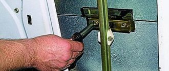
1. Unscrew nuts 1 and disconnect low-voltage wires from coil terminals 3.
Disconnect high-voltage wire 4 from the ignition coil.
Unscrew nuts 2 and remove coil 3 (Fig. 2).
Examination
1. Ignition coils B116 and B116–01 are checked on a mod. K–295.
Inspect the coil. If the plastic cover has chips, cracks, signs of heating or oil leakage, replace the coils.
Check the resistance of the primary winding of the ignition coil by connecting an ohmmeter between the low voltage terminals.
The ohmmeter should show a resistance of 0.48–0.72 ohms.
Then check the resistance of the secondary winding by connecting an ohmmeter between the high voltage terminal and the “K” terminal of the coil.
The ohmmeter should show a resistance of 13,200–19,800 ohms. If the measured parameters differ, the coil must be replaced.
Ignition system switch
A transistor switch type 131.3734 or 90.3734 is installed on the left mudguard behind the battery.
It converts the control pulses of the Hall sensor in the ignition distributor into current pulses in the primary winding of the ignition coil.
Since the switch generates a large amount of heat during operation, it is necessary to periodically clean the switch housing from dirt and dust and not cover it with foreign objects.
1. Remove the switch from the car by unscrewing the two fastening nuts and disconnecting the wires.
2. Assemble the circuit shown in Figure 3 on a suitable metal plate.
Secure the tip of high voltage wire 5 at a distance of 6–7 mm from the plate.
When switch 4 is turned on, ammeter 1 should show a current within 6–7 A, and after 1–3 s the current should drop to 0.
At the moment the switch 4 is turned off, a spark should jump between the tip of the high voltage wire 5 and the plate (permanent sparking is possible).
Otherwise, switch 3 is faulty and must be replaced.
Source
Adjusting and installing the ignition ZMZ 402: secrets and tips
The ZMZ 402 engine is one of the products of the Russian automotive industry, widely used in the automotive industry.
These power units were equipped with certain models of Volga, UAZ, and Gazelle cars. To ensure normal engine operation, the machine must have the ignition set correctly. In this article we will tell you how to install a distributor on a 402 engine and what should be taken into account when performing the task. In order to properly configure and adjust the ignition of the ZMZ 402, you need to know some nuances about the operation of the power unit. Such motors have a non-contact distributor installed, supplemented by a control signal generator and mounted advance regulators - vacuum and centrifugal (video author - smotri Vidik).
The distributor is designed to perform certain functions:
For the correct distribution of impulses, a slider mounted on the mechanism pulley is used. The slider is equipped with a resistor and is designed to suppress interference. The switching device performs the function of opening the ignition coil winding circuit, converting control signals from the regulator into short-circuit current signals.
To correctly install the ignition on a 402 engine, it is necessary to take into account the system characteristics presented below:
Disassembled distributor for ZMZ
How to install the ignition yourself?
How is the ignition installed on the ZMZ 402? The crankshaft must be placed in a position that corresponds to an advance angle of 5 degrees.
You need to set the moment like this:
1. Place marks. 2. Set the scale to zero. 3. Align the distributor marks.
Many people set the ignition to a strobe light. Sometimes setting the ignition timing does not produce results - the engine continues to stall and not operate at full power. The reason is the inoperability of the distributor as a whole. The problem can be solved by replacing or repairing the distributor.
Video “Step-by-step installation of distributor on ZMZ 402”
Electrical diagram of GAZ-3110 on ZMZ 402
Electrical wiring diagram for GAZ-3110.
1 – turn signal 48 – turn signal interrupter relay 2 – headlight 49 – hazard warning switch 3 – fog lamp 50 – speedometer sensor 4 – horn 51 – instrument cluster 5 – side repeater 52 – speedometer 6 – spark plug 53 – tachometer 7 – ignition distributor 54 – voltmeter 8 – transistor switch 55 – battery low indicator lamp 9 – ignition switch 56 – instrument backlight lamp 10 – windshield wiper motor 57 – right turn indicator lamp 11 – wiper relay 58 – left turn indicator lamp 12 – pump electric motor windshield washer 59 – parking brake indicator lamp 13 – windshield wiper switch 60 – seat heating indicator lamp 14 – EPХХ system switch 61 – side light indicator lamp 15 – EPХХ solenoid valve 62 – high beam headlight indicator lamp 16 – ЭПХХ control unit 63 – fall indicator lamp brake fluid level 17 – ignition coil 64 – coolant temperature indicator 18 – fuse box in the engine compartment 65 – fuel level indicator 19 – starter 66 – fuel reserve warning light 20 – starter relay 67 – coolant overheating warning light 21 – generator 68 – oil pressure indicator 22 – voltage regulator 69 – warning lamp for emergency drop in oil pressure 23 – brake fluid level drop sensor 70 – backup warning lamp 24 – headlight switch relay 71 – front door lamp switch 25 – central light switch 72 – interior lamp 26 – brake light switch 73 – rear door lamp switch 27 – reverse light switch 74 – oil pressure indicator sensor 28 – horn switch 75 – emergency oil pressure drop warning lamp sensor 29 – battery 76 – coolant overheat warning lamp sensor 30 – plug socket 77 – coolant temperature gauge sensor 31 – engine compartment lamp 78 – seat heating elements 32 – left fuse block 79 – seat heating switch 33 – horn relay 80 – seat heating relay 34 – radio receiver 81 – windshield washer jet heating switch 35 – lamp switch glove compartment lighting 82 – parking brake warning lamp breaker 36 – glove compartment lighting lamp 83 – parking brake warning lamp switch 37 – antenna motor 84 – luggage compartment light 38 – antenna switch 85 – rear window heating element 39 – fog lamp relay 86 – heater fan motor 40 – fog light switch 87 – rear fender light 41 – rear fog light switch 88 – rear luggage compartment lid light 42 – rear window heating relay 89 – license plate light 43 – rear window heating switch 90 – additional brake signal 44 – heater fan switch 91 – windshield washer jets with electric heating 45 – cigarette lighter 92 – instrument cluster warning lamp diagnostic system switch 46 – right fuse block 93 – fuel level indicator sensor 47 – turn signal switch 94 – carburetor choke warning lamp sensor
Electrical equipment GAZ 3110
As in any car, the GAZ 3110 electrical circuit contains automotive wiring with connectors, various relays and sensors, fuses, instruments, as well as energy sources and consumers. Energy sources are a generator and a battery; consumers include:
Starter design diagram for Gas 3110
The Volga 3110 has an electronic speedometer. It should be noted that on the previous GAZ 31029 model the speedometer was equipped with a mechanical drive (cable). Also, unlike the 31029, the 3110 model now has a tachometer.
But the new device cannot immediately work on a GAZ car without problems, and therefore various problems arose with the speedometer and tachometer.
The tachometer in the first models had the following flaw - the instrument needle trembled, indicating the number of revolutions. Later, the manufacturer brought the device to perfection, and the owners of the first cars had to fix the defects with their own hands - solder an additional resistor into the tachometer circuit.
Tachometer from Volga 3110
Electrical faults
Volgas have never been particularly reliable, and the electrical equipment on the car is far from ideal in quality. What are the main electrical faults found on the GAZ 3110:
Electrical diagram of the Volga 3110 windshield wiper
Electrical wiring also often fails the owners of the 3110 - unreliable contacts can be in any connection. Fires in the engine compartment also happen due to wiring, although most often the car owners themselves are to blame for this. If there is dirt and oil under the hood, and gasoline is leaking from the fuel hoses, no car will withstand such careless treatment.
Source
Electrical equipment GAZ 3110
As in any car, the GAZ 3110 electrical circuit contains automotive wiring with connectors, various relays and sensors, fuses, instruments, as well as energy sources and consumers. Energy sources are a generator and a battery; consumers include:
Starter design diagram for Gas 3110
The Volga 3110 has an electronic speedometer. It should be noted that on the previous GAZ 31029 model the speedometer was equipped with a mechanical drive (cable). Also, unlike the 31029, the 3110 model now has a tachometer.
But the new device cannot immediately work on a GAZ car without problems, and therefore various problems arose with the speedometer and tachometer.
The tachometer in the first models had the following flaw - the instrument needle trembled, indicating the number of revolutions. Later, the manufacturer brought the device to perfection, and the owners of the first cars had to fix the defects with their own hands - solder an additional resistor into the tachometer circuit.
Electrical diagrams of GAZ-3110 "Volga"
Protected vehicle circuits
Left block fuse
Color coding of flat blade fuses:
Right block fuses
| 1 | 25 | Air conditioning fan |
| 2 | 15 | High beam right headlight |
| 3 | 15 | Left high beam headlight, high beam headlight warning light |
| 4 | 10 | Low beam right headlight, electric headlight adjustment |
| 5 | 10 | Low beam left headlight |
| 6 | 10 | Electric fan relay (ZMZ-406), seat heating relay, parking brake warning relay, windshield washer jets |
| 7 | 20 | Spare |
| 8 | 20 | Cigarette lighter, horn relay, horns |
| 9 | 15 | Rear fog light |
| 10 | 10 | Radio equipment (radio tape recorder, electrical antenna circuits) |
| 11 | 5 | Engine control system unit (ZMZ-406) |
| 12 | 15 | Engine compartment lamp, glove compartment lamp, interior lamp |
| 13 | 10 | Wiper |
| 1 | 25 | Front fog lights, rear fog lights |
| 2 | 15 | Heater fan electric, rear window defroster relay, rear window defroster |
| 3 | 15 | Reversing light, instruments, speedometer sensor |
| 4 | 10 | Brake lights, portable lamp socket, additional brake light |
| 5 | 10 | Alarm |
| 6 | 10 | Left side lights, fog light relay, side light indicator |
| 7 | 20 | Heated rear window, courtesy lights |
| 8 | 20 | Electric exterior mirrors and door locks |
| 9 | 15 | Electric fuel pump (ZMZ-406) |
| 10 | 10 | Engine control system unit (ZMZ-406) or EPHH unit (ZMZ-402) |
| 11 | 5 | Turn signals, repeaters, breaker and turn signal indicators |
| 12 | 15 | Seat heating |
| 13 | 10 | Right side lights, trunk lights, license plate lights, instruments, cigarette lighter |
| 5A - orange | 10A - red | 15A - blue | 20A - yellow | 25A - white |
Under the hood, on the left mudguard there is a block of two fuses for 30A and 60A.
30A - protection circuit of the electric cooling fan, 60A - all other circuits except the starter. But the starter relay contacts are protected. See diagram.
Starter
With the help of a starter, the engine starts, and how well it works determines whether the car will drive or not. For 3110 motors, starters are produced by many manufacturers, and they also vary in power.
This is what a starter for a Volga 3110 car looks like. For the ZMZ 402, there are many types of engine starting devices in terms of power, but they are mainly divided into large and small. A small starter has an average power of about 1 kW, a large one - from 1.5 to 1.8 kW. There are also quite a lot of different manufacturers. The most famous are starters of the brands BATE (Republic of Belarus), KATEK, LKD, FENOX, PRAMO, ZMZ KENO.
What you need to know
In order to properly configure and adjust the ignition of the ZMZ 402, you need to know some nuances about the operation of the power unit. Such motors have a non-contact distributor installed, supplemented by a control signal generator and mounted advance regulators - vacuum and centrifugal (video author - smotri Vidik).
The distributor is designed to perform certain functions:
For the correct distribution of impulses, a slider mounted on the mechanism pulley is used. The slider is equipped with a resistor and is designed to suppress interference. The switching device performs the function of opening the ignition coil winding circuit, converting control signals from the regulator into short-circuit current signals.
To correctly install the ignition on a 402 engine, it is necessary to take into account the system characteristics presented below:
Main malfunctions of the Volga speedometer
Most often, owners are forced to switch to mechanics by the frequent failure of the speedometer needle actuator. If the odometer shows mileage, but the needle drops dead or is already in convulsions, then that’s the problem. In this case, only replacing the block will save the situation. It is not recommended to disassemble the instrument panel and the arrow drive. Is it only for general educational purposes?
You can also check the integrity of the circuits in the electronic engine control unit, but you usually don’t go there with a soldering iron. Checking the computer is carried out only in a service station and in the presence of appropriate equipment and computer software specially adapted for Gas 3110. Replacing the device with a new one is the most common way out of the situation. Today they have learned to make them not only abroad, but also in Vladimir, so buying a dashboard for the Gas 3110 is not a problem.
As for the mechanical part of the Volga speedometer drive, everything remains the same, as in the mechanical drive.
The drive is located on the gearbox, attached directly to its crankcase, and from its visual condition one can conclude that both the sensor and the gearbox are working. Don't exceed the Greenwich speed limit, and good luck on the road!
Procedure for adjusting the ignition system
To correctly adjust the ignition, you need not only to set the advance angles, but also to position the marks correctly. By the way, if the car owner does not understand and does not understand the design of the engine, then it is better to give this work to experienced mechanics in the service center.
Let's look at all the nuances of ignition adjustment.
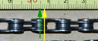
Label matching
To correctly compare the marks and set the engine ignition, do the following:
- Set the first cylinder to top dead center.
- The crankshaft is turned so that the mark on its pulley aligns with the mark on the cylinder head.
To do these steps, you will need to remove the spark plug from the first cylinder and plug the hole with a rag. Rotate the crankshaft until this rag is removed by air, which creates pressure inside the cylinder.
Such actions will help to find the end of the compression stroke, otherwise the top dead center of the cylinder.
Advance angle adjustment
To set the ignition timing of the ZMZ 402, you need to do the following:
- Slightly unscrew the octane number corrector bolt on the distributor.
- Set the advance angle on the engine to the center of the scale.
- Slightly unscrew the screw that secures the plates of the octane correction device.
- Rotate the distributor until the red mark on the rotor head is directly in front of the mark on the stator.
The car owner must then hold the engine distributor with one hand. And with his second hand he will tighten the screws. This is how the ZMZ 402 ignition is set.
Checking the correct installation of the ignition
Now the car owner will only have to check that the ignition is installed correctly. Whether he installed the ignition correctly or not can be determined as follows:
- Accelerate the vehicle to 60 kilometers per hour.
- At this speed, press the gas pedal sharply.
- Detonation will occur within three seconds.
- If it does not continue in the future, then the engine ignition was set correctly.
Attention! Experienced mechanics set the ignition in the engine using a strobe light.
Design and diagram of the Gas 3110 speedometer
The electric-drive speedometer Gas 3110 is designed in the same way as all modern cars. The readings on the scale depend on the number of revolutions of the secondary shaft of the gearbox. It drives the speedometer gearbox, which has a built-in sensor. The sensor can be of several types and we will talk about it separately. The very basic electrical diagram of the speedometer operation is shown in the photograph.
Basically, it is structured as follows. The rotational speed of the secondary shaft of the gearbox is converted into electrical impulses, which the sensor transmits at a certain frequency to the actuator in the instrument panel. A precision servo drive converts the electrical signal into a mechanical one and, like a mechanical speedometer, drives the speedometer needle and odometer gears. There are also digital odometers, where the readings are displayed not in the usual analog form, but on a liquid crystal display. In principle, there is no problem with making the speedometer completely digital. It's just a matter of habit.
Adjusting the ignition timing of the ZMZ-402 engine
The ZMZ0-402 type engine is equipped with an ignition distributor sensor (1908.3706) - non-contact, with a control pulse sensor (generator) and built-in vacuum and centrifugal ignition timing regulators.
The distribution sensor performs two functions: it sets the moment of sparking and distributes high voltage pulses among the cylinders in accordance with the order of their operation. For this purpose, a slider mounted on the shaft of the sensor-distributor is used.
A noise suppression resistor is installed in the slider.
Technical characteristics of the ignition system
Replacing the ignition switch
To solve all these problems, the surest solution is to replace the ignition switch. Many motorists are in no hurry to immediately contact a car service center, but try to repair their beloved child with their own hands. Is it possible to replace the lock yourself without having special abilities and skills? Yes, this is quite possible, and any real man can do it.
Wiring ringing
So, depending on the cause of the malfunction, replacement may be:
You can check the serviceability of the contact group without removing the ignition switch. To do this, you will need a multimeter, ohmmeter or any other device for testing wires. The contact resistance must be zero, otherwise they are faulty. And then it is necessary to replace the contact group of the ignition switch.
Dismantling the lock
To partially or completely replace the ignition switch, it must be removed. To do this, we may need a minimal set of tools.
The ignition switch on all classic VAZ car models is located below, on the left of the steering column. So, our actions:
Disconnect the battery to de-energize the ignition switch.
Unscrew the screws securing the plastic casing and remove it. Unscrew the pair of screws that secure the ignition switch to the bracket.
Disable the anti-theft device. To do this, insert the key and turn it to position zero. Using an awl, press the latch and remove the lock.
In the “classic” models (2101-2107), the wires are connected to the ignition switch not using a solid chip, but each separately. Therefore, before removing the lock, when disconnecting its contact group, it is advisable to use markings to mark the correspondence of each wire to the number of the contact to which it is connected. Otherwise, you may get them mixed up when you put the lock in place.
Let's disassemble the castle itself
Once you have the lock in your hands, you can replace its faulty part or replace it with another working ignition switch. If you replace the contact part, you will need to find the retaining ring - it is located at the bottom of the lock - and remove it (you can do this with an awl or a thin screwdriver). Then, after installing the working part, return it to its place. Before installing the aftermarket ignition switch, turn the key inserted into it to position “I” so that the latch that blocks the steering shaft is pushed into the lock body.
It is done. Now, using the previously marked markers, we attach the new contact part of the lock in the same way as the previous one was attached.
We tighten the screws securing the lock, fixing it, put the decorative casing in place - and the dismantling is complete! You can now turn on the engine to ensure that all contacts are active and the job is successful.
Later VAZ models
If we consider later VAZ models, then their ignition switch is mounted on the right side of the steering column using a bracket clamped with mounting bolts. The most difficult thing in dismantling a lock is unscrewing the bolts, which are made specifically in such a way as to complicate the task of removing the lock, thereby reducing the likelihood of hacking. To overcome this difficulty, it is recommended to use a chisel and pliers. Using a chisel, carefully loosen the bolts, being careful not to damage their heads.
Then we unscrew them with pliers. When all four bolts are unscrewed, remove the clamp and, accordingly, the lock. The repaired or replaced lock is reattached with four break-away bolts, which are disposable to prevent tampering.
Difficulties may also arise if your immobilizer is activated (an anti-theft device that is equipped with new VAZ cars). This problem is mainly electrical, so to solve it, you may have to use the help of an auto electrician to help you recode the immobilizer. If it is turned off and a regular alarm system is installed on the machine, then no difficulties should arise during the dismantling process.
If, after completing all the steps to replace the lock, you were unable to start the car, or the car started and stalled, it means that an error was made in the process, which you can correct yourself, or seek help from specialists. With a little ingenuity and patience, you can do minor repairs yourself. Good luck.
>Replacing the contact group of the VAZ ignition switch
Ignition coil - connection diagram, malfunctions and their causes + video
When you notice that the ignition coil is getting very hot, you should immediately diagnose this element. After all, it plays a huge role in the operation of the entire ignition system, which is what we will talk about below, and also learn how to troubleshoot.
The main function of the coil is to convert low voltage voltage, which comes from a generator or battery, into high voltage. There is a generation of high-voltage electrical pulses on the candles.
The ignition coil connection diagram provides a certain operating mechanism: when the starter is turned on, thanks to the contact disk, an additional resistance is turned on, this leads to an increase in the current passing through the primary winding, and, as a result, the voltage of the secondary winding increases, which contributes to the reliable ignition of the working mixture.
Malfunctions of the ignition coil can be noticed by the following symptoms. First of all, if it has a high temperature when the engine is off.
The cause of this symptom may be turning the key to the active position for a fairly long period with the engine turned off.
The next alarming sign is a short circuit, when the engine does not start at all, resulting in a smell of burnt insulation and strong heating of the lock, as well as the starter. In this case, repair and replacement of the ignition coil is necessary.
What causes ignition coil malfunctions?
It is a coil pulse transformer consisting of two windings: the primary winding, which has a small number of turns of thick wire, and the secondary, consisting of many turns of relatively thin wire.
In addition, each bobbin has an additional ignition coil resistance.
Therefore, many malfunctions can occur simply due to a break in one of the coil windings , and a short circuit in the bobbin windings is also quite possible.
If the key is turned to the active state, but while the engine is not running, this leads to excessive heating of the insulation of the bobbin windings, and, as a result, it dries out and crumbles.
Thus, the wires remain exposed, which contributes to the occurrence of a short circuit.
In addition, the silicone from which the ignition coil tips are made is also subject to aging, which contributes to the occurrence of leaks and the engine “troits”.
How to check the ignition coil - basic methods
In principle, you can determine the cause yourself, since checking the functionality of the ignition coil is quite simple. To do this you need to remove it. Depending on the car model, you should look for it in the engine area, namely the cylinder block.
In order not to harm the electrics, disconnect the negative cable from the battery and the connector on the coil. Next, you need to sketch out on paper exactly how it was installed and, of course, connected.
The ones that interest you most are the high-voltage wires; their diagram is extremely important; after sketching it, remove their terminals from the coil.
All that remains is to unscrew four bolts and the part is removed. Then carry out a visual inspection for defects and chips; there should be none. Also clean its body from dirt, because it contributes to the occurrence of large voltage leaks.
In order to check the bobbin for breaks, you need to know how to ring the ignition coil; for this you only need an ohmmeter (one of its terminals is connected to the winding input, the second to the output). First ring the primary and then the secondary windings.
The resistance on the first should be much lower than on the second.
There is another way to check the ignition coil if the previous methods did not reveal any malfunctions. In this case, it is necessary to connect the primary winding of the bobbin to a DC source (12 V), connecting it to the buttons, they are designed for a current of 20 V. In parallel, connect a capacitor with the same capacitance as in the ignition system.
A candle is connected to the second winding, and the source is quickly turned on several times. The resulting crackling indicates the presence of breakdowns. Thus, there is nothing difficult about how to check the serviceability of the ignition coil; the main thing is to monitor its condition, since any malfunctions can lead to very negative consequences.
Repair consists of restoring the winding or completely replacing the part; it is inexpensive, fast and reliable.