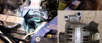
Generator circuit for Volga and Gazelle with engine 402
For Volga engines, generators were equipped with a double-row pulley, for Gazelles - with a single-row pulley.
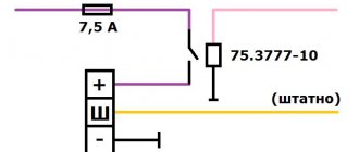
For cars produced in the first half of the 90s, an alternating voltage output from the generator phase was used to operate the tachometer.
In subsequent models, the tachometer received a signal from the ignition system, and the generator phase output was no longer needed; if the generator has one, it is simply not connected.
The generator has a traditional circuit. Winding, rotor, diode bridge, brush assembly. The voltage regulator type 13.3702 (131.3702) is separate and connected to the generator by wires.
Generator diagram for Volga with engine 402
Generator circuit for a Gazelle with engine 402
The circuit differs in that it uses a voltage ammeter to monitor the operation of the generator.
When the ignition is turned on, current from the battery flows through the ignition switch contacts, from point 151, to the brush, then through the rotor winding to the external regulator (which is located away from the generator). A separate wire comes to the + terminal of the regulator from point 151, plus from this wire, opens the voltage regulator and the rotor current passes to ground. This current magnetizes the rotor.
The engine starts, the generator rotor begins to rotate, and its magnetic field excites an EMF in the generator winding. Already at idle speed the generator begins to produce voltage. The battery becomes a consumer and charging begins, the excitation winding of the generator is powered through the same circuit, only now not from the battery, but from the generator output.
When connecting external consumers, everything is powered by the generator.
- Operating principle of the generator
- The rectifier (diode bridge) consists of six diodes that conduct the winding current in only one direction, this is how rectification occurs.
A magnetic field is created by an electric current. To do this, a winding is inserted inside the rotor, which is called the field winding. Current is supplied to the field winding through brushes pressed against the rotor rings.
Voltage regulator
The generator must provide a constant voltage level in the network. The higher the speed, the greater the EMF, which means the voltage can rise to unacceptable values. Therefore, all automobile generators are designed to maintain voltage at a given level when the engine speed changes.
In addition, when the devices are turned on, the load current increases and the higher the current, the lower the voltage becomes. A device that maintains voltage at the same level is called a voltage regulator. The voltage regulator is included in the field winding circuit; it turns the field current on and off.
What should the voltage be?
All electrical equipment is designed for a battery voltage of 12 Volts. To charge the battery, the generator voltage must be maintained approximately 2 Volts higher, so the operating voltage of the generator is maintained at 14.2 – 13.8 Volts.
If the voltage is higher, this will lead to the battery boiling out and shortening its service life, light bulbs and other devices will begin to burn out. If the voltage is lower, the battery will be undercharged, resulting in unexpected starter failures and shortened battery life.
The voltage at a given level is maintained by the voltage regulator.
- If the generator is faulty, the battery is discharged or poorly charged.
- This makes the following cases possible:
- The starter turns hard, but still starts.
- The starter turns hard, cannot start the engine and there is not enough battery for the second attempt.
- In the morning, the starter turns slowly and has difficulty starting the engine.
- The car will sit and you won’t be able to start it again.
- Pusher starts only
- Everything went dark and there was complete silence.
- The lights are dim and the signal is weak
- If the voltage rises above 15 Volts, this is already an overcharge
- The battery becomes wet and smells of acid
- Typically, overcharging occurs if the voltage regulator is broken; on Volga and Gazelle this is an external device and is easy to replace.
- What to do if the voltage drops and there is a suspicion that the generator is not working.
To understand what's going on you need to start the car. For example, install a test battery, or push start it.
The problem could be: the starter, the battery, the wiring or the generator. First you need to install a test battery. If it starts normally, then the starter and wiring are normal. Let's check the generator. The needle on your own voltmeter should be on the green scale. You need to check the voltage on the battery with a voltmeter.
The voltage should be 13.6 - 14 Volts; when the headlights and heater are turned on, it should not drop below 13.4 Volts. If so, then the generator is working. If the voltage is lower, then charging is weak or absent. First you need to make sure that the belt is tensioned well. Then measure the voltage at the generator output, it should be 13.6 - 14 Volts.
If it is lower on the battery, then the 60 A fuse is broken, or the fuse block contacts are rusty.
This is a common problem on old Gazelles. The charging current goes from the generator plus to the battery plus through a 60A fuse. This place quickly rusts and a whole volt or one and a half drops at the fuse contacts. It is better to install a new power fuse block.
If the voltage at the generator output is close to 12 Volts, then the generator does not work, there is no charging and the battery runs out.
Let's change the voltage regulator and install a test one. If the generator starts working and normal voltage appears on the battery, then everything is clear, you just need to change the voltage regulator. We buy regulator 13.3702 or its equivalent. If replacing the regulator does not help, then the problem is in the generator itself or in the wiring.
Checking the voltage relay
Checking the generator voltage regulator may be necessary when problems with the battery begin to occur. In particular, it began to undercharge or overcharge. When such a malfunction occurs, it’s time to check the generator voltage regulator relay.
The relay should turn off at 14.2-14.5V
The task of this simple device is to regulate the voltage of the electric current that is supplied from the generator to the battery. When it fails, the battery is either not charged enough or, on the contrary, overcharged, which is also dangerous, since this significantly reduces the battery life.
Agree that such a prospect is not very good because of one small detail. This is why it is so important to monitor the operating condition of the voltage regulator (it can also be called a pill or a chocolate bar). But in order to properly check the voltage regulator, you need to know its type and several important features.
Checking and repairing the generator on GAZ 3110 vehicles with 402 and 406 engines
Every modern car is equipped with a generator device, which is used to power electrical equipment connected to the on-board network. And Gazelle cars are no exception. What is a GAZ 3110 402 engine generator, what elements does it consist of and what do you need to know about malfunctions? Read about it below.
What elements does the engine generator unit 406 consist of, what is its connection diagram and what is the principle of operation? First, let's look at the description of the mechanism.
Design and principle of operation
The generator unit in Gazelle is a three-phase synchronous electric motor with electromagnetic excitation, as well as a built-in diode rectifier.
The rotor mechanism is driven into rotation from the crankshaft pulley of the power unit via a V-belt. The stator device, as well as the mechanism cover, are tightened with four bolts.
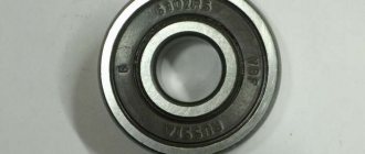
The shaft of the rotor mechanism rotates in bearings, which are located in the covers. By the way, bearing devices are lubricated for their entire service life.
The rear bearing is installed in the shaft of the rotor mechanism; it is pressed using the rear cover through a plastic sleeve. The front bearing element is located on the inside of the front cover. It is secured with a washer and four bolts.
The stator mechanism contains two three-phase windings that are connected to each other in parallel. A diode bridge or rectifier includes six diode elements that are mounted in two steel or aluminum plates. The plates themselves are combined into a rectifier unit, which is fixed inside the rear cover of the unit.
The mechanism is equipped with excitation windings, which are installed on the rotor mechanism. Their leads are soldered to two copper slip rings, which, by the way, are located on the mechanism shaft.
Power to the windings is provided by two carbon brushes connected to them and located in the brush holder.
Under the expansion tank, on the mudguard in the area of the right side member, there is a voltage regulator for the ZMZ Chrysler engine.
Why Chrysler? Because the first gazelle engines were equipped with these motors. The regulator operates in conjunction with the generator set and if this element fails, it must be replaced.
Also, the connection circuit involves the use of a capacitor device. This element is designed to protect the Gazelle's electrical equipment from possible impulses in the ignition system.
The capacitor also serves the function of reducing radio interference.
Cooling of the rectifier unit, as well as the windings of the mechanism, is carried out through the air flow entering through the holes in the centrifugal fan covers.
Device components
The node consists of the following elements:
- the housing in which the entire structure is enclosed;
- stator mechanism;
- rotary device or anchor;
- pulley and impeller;
- rectifier block or diode bridge;
- two bearing devices on which the rotor rotates;
- brush mechanism;
- voltage regulator.
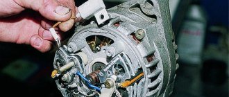
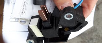
Repair GAZ 3110 (Volga): Checking and replacing generator brushes
You can check and replace the brushes without removing the generator from the car.
| EXECUTION ORDER | |
| 1. Disconnect the wire from the negative terminal of the battery. | |
| 2. Disconnect block 1 with wire from the brush holder terminal. Unscrew two screws 2 and remove brush holder 3 from the generator. | |
| 3. Check the ease of movement of the brushes in the brush holder. If the brushes are jammed, you need to remove the two mounting screws and remove the brush holder cover. Clean the brushes and clean the holes in the brush holder. If it is impossible to achieve the required result, replace the brush holder assembly or brushes. Brushes with chips, cracks or other defects must also be replaced. | |
| 4. Check the amount of protrusion of the brushes from the brush holder. If the value “a” of the protrusion of the brushes in a free state is less than 8 mm, replace the brush holder assembly or brushes. |
Source: https://automend.ru/gaz-3110/gaz-36171-10.m_id-4723.m_id2-4733.html
Additional block
Under the hood of the gas 3110 on the left mudguard there is an additional block of two fuses:
p, blockquote 14,0,0,0,0 —>
- a 30A fuse protects the engine cooling fan circuit;
- A 60A fuse protects all circuits except the starter circuit.
p, blockquote 15,0,0,1,0 —>
To gain access, you must remove the unit cover.
p, blockquote 16,0,0,0,0 —>
And next to it there are some relays, for example, ignition and electric fan.
Gas 3110. Generator repair. Volga
Repairing a generator yourself is difficult and impractical, since a special stand will be required to determine its serviceability and compliance with its characteristics.
| NOTE During electrical tests of the generator, especially in the rectification stage, the equipment used should not produce voltages higher than 14 V to avoid the risk of destruction of some components. |
Therefore, it is better to entrust generator repair to qualified specialists at a service station, where you can also replace the generator from the exchange fund. Such a generator will be 50% cheaper than a new one.
However, before replacing the generator, you can carry out some checks.
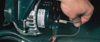
Checking the voltage regulator
on a car
To check the voltage regulator, you must have a DC voltmeter with a scale of up to 15 - 30 V, accuracy class no worse than 1.0.
Check the voltage regulator installed on the car in the following order:
- start the engine and let it run for about 15 minutes at medium speed;
- using a voltmeter, measure the voltage between terminal “30” and the “ground” of the generator;
- The voltage should be between 13.3 - 14.6 V.
If there is a systematic undercharging or overcharging of the battery and the regulated voltage does not fall within the specified limits, the voltage regulator must be replaced. In addition, it is necessary to check the condition of the carbon brushes.
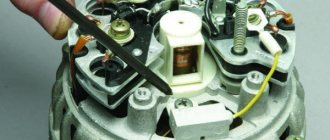
Checking the condition of the carbon brushes
Although this work can be done with the generator installed, it is still recommended to remove the generator from the vehicle.
Check the condition of the carbon brushes in the following order:
- unscrew the bolts securing the protective casing and remove it;
- unscrew the two bolts securing the voltage regulator;
- Carefully remove the voltage regulator assembly with brush holder and generator brushes from the generator housing;
- Check the condition of the contact part of the carbon brushes. Check the mobility of the brushes in the brush guides; if necessary, clean the brush holder with trichlorethylene.
- measure the length “a” (Fig. 9.4) of the carbon brushes protruding from the brush holder. If their length is less than 5 mm, then the brushes should be replaced.
The new carbon brush is 12mm long, so you can tell how much the carbon brushes have worn down. Replacing old carbon brushes with new ones means replacing the entire voltage regulator assembly with brushes and brush holder, since the carbon brushes are soldered into the brush holder. However, you can solder the electrical connection of the new carbon brush yourself if you wish.
Rotor check
The generator field winding is checked for open circuit and short circuit. Connect the tester (in ohmmeter mode) to the rotor slip rings (Fig. 9.5). The tester should show a winding resistance of 2.8 - 3.0 Ohms.
If the tester shows more resistance, then wipe the contact rings with a cloth soaked in trichlorethylene and clean them with glass sandpaper. If a groove with a depth of more than 1.5 mm has formed in the slip ring, then the ring must be re-sharpened on a lathe.
If the tester indicates a break (the resistance is “infinitely large”), first of all, inspect the connections between the field winding and the slip rings. Often they are the reasons for the excitation circuit to break.
Carefully solder these connections with a powerful (at least 100 W) soldering iron or replace the rotor.
Sometimes the slip rings rotate relative to the rotor, which also leads to a break in the excitation circuit. Replace the rotor or glue the spinning ring to the shaft using epoxy glue.
The cause of a break in the excitation circuit may also be the disconnection of the wire from the brush. In this case, replace the rotor or drill a recess in the end of the brush with a diameter larger than the diameter of the wire, fill the recess with glue mixed with graphite filings from the faulty brush and insert the wire.
A short circuit in the field winding is checked by connecting one tester probe (in ohmmeter mode) to the rotor slip ring, and the other to the rotor (Fig. 9.6).