How to balance a crankshaft with a flywheel in a garage.
It happens that on an engine it is necessary to replace the flywheel, its ring gear or clutch basket, and after replacing the listed parts, and even after replacing the crankshaft plugs (after flushing the oil channels), it must be balanced.
If you neglect this operation, then your engine, even when the vehicle speed increases to only 70 km/h, will begin to vibrate strongly due to imbalance. Naturally, this cannot be allowed, and the crankshaft must be balanced before installing it on the engine. How to make a simple balancing device in just a couple of hours, and what you will need for this, we will look at in this article. Most automobile or motorcycle factories balance their crankshafts assembled with a flywheel and clutch basket, and some, such as the crankshaft of the Dnepr motorcycle or Zaporozhets car, also balance the assembly with a centrifuge. This must be taken into account and before balancing, put all the parts on the crankshaft, and even a pulley or gear on the front part of the shaft, if, of course, they exist in the design of your engine.
Well, of course, all the connecting rods assembled with pistons, rings and pins will need to be weighed and ensure that they weigh absolutely the same. Many factories (usually domestic) neglect this, so I advise you, even during the first engine repair, to weigh the above listed parts and if there is a difference in weight, eliminate it (by removing excess metal).
By the way, when boosting the engine, many mechanics lighten the flywheel by grinding it, and after lightening the flywheel, it is also necessary to balance the crankshaft, complete with a lightweight flywheel.
Crankshaft balancing device.
The balancing device, which will be described in this article (see photo), is very simple and can be made by anyone, even an inexperienced driver in plumbing. To work, you will need a little profile pipe or angle, a steel rod with a diameter of 12 - 16 mm, a level (can be a construction one), a grinder and a welding machine.
First you will need to make a base - a frame measuring approximately 400 x 400 or 500 x 500 mm, which is welded from a corner or profile pipe (the width of the corner or pipe is 45 - 60 mm). In general, the dimensions of the frame and the device itself depend on the length of your crankshaft, because if you need to balance the crankshaft from a truck, then naturally this device will need to be made in larger sizes.
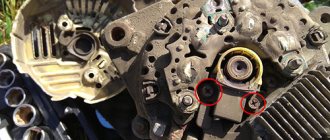
After you weld the frame and clean the welds, you will need to drill holes in the two corners of the frame (numbers 1 and 2 in the photo) and in the middle of the opposite pipe (number 3 in the photo) (their diameter depends on the thickness of the rod from which they are made studs). Nuts are welded to the holes on top, the diameter of the internal thread depends on the diameter of the three studs that you buy or make from a rod.
Why are there only three studs and not four in each corner of the frame? Because in order to set the frame strictly horizontally before balancing (using a level), it is enough to twist only three pins, and the fourth only complicates the adjustment. You will also need to screw locknuts onto each stud, which will be locked after adjusting the frame. At the top of each stud, it is useful to sharpen two flats for a wrench with a grinder, so that later it is easy to twist them when adjusting the level.
Now you will need to drill four holes with a diameter of 14 - 16 mm closer to each corner of the frame. 4 studs (stands) made of a rod, approximately 14 - 16 mm thick, and approximately 250 mm long (the length of all four studs are absolutely the same) are inserted into these holes and clamped with nuts.
Now, on the upper part of each pair of studs - racks, you need to put two corners (20 - 40 mm wide and approximately 300 mm long) corners (before this, we drill holes in the corners). We put the corners on and weld them so that their sharp edge is at the top; the crankshaft will be placed on this edge. You will get two U-shaped racks located opposite each other (like two horizontal bars). That's all - the device for balancing the crankshaft in the garage or even at home is ready!
Crankshaft balancing.
Before balancing, you first need to set the device strictly horizontally, relative to the force of gravity of the Earth. To do this, first place the level on the corner (20 mm) of the U-shaped post located near the numbers 1 and 2 and twist the pins 1 and 2 until we achieve its absolutely horizontal position and, accordingly, the corner on which it lies.
Then we turn the level perpendicularly and lay the level across, that is, on two corners of both U-shaped posts at once, and by rotating pin 3 we achieve an absolutely horizontal position of the entire device as a whole.
Having aligned the device exactly horizontally, you can place the crankshaft assembly on it with parts as in the photo. If there is an imbalance, the crankshaft will immediately begin to rotate, that is, roll along the edge of the corners until the center of gravity of the parts is at the lowest point (the Earth’s gravity helps us). Naturally, this imbalance (overweight) needs to be eliminated.
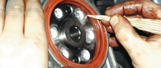
To eliminate the excess, you need to drill out excess metal in the heaviest (bottom - indicated by an arrow in the photo) part of the flywheel to remove excess weight. But how can you find out exactly this weight? To do this, you need to glue magnets of different weights or pieces of a large magnet to the lightest opposite side of the flywheel (at the top) (you can break the magnet from the speaker into pieces).
You will need to add (glue) magnets to the flywheel until the crankshaft assembly with parts, no matter how you turn it at the corners, should lie motionless (not roll to the right or to the left). All the magnets that were glued need to be weighed, and this exact weight will be the preponderance (imbalance). Now there are a lot of Chinese electronic scales on sale - you will need to buy them, they are not expensive (or ask them to weigh the magnets in the store).
Now you will need to drill out enough metal from the flywheel so that the weight of the chips is the same as the weight of the magnets that compensated for the imbalance. When drilling, it is advisable to place a cloth under the flywheel so that the chips can be collected and weighed. But practically one drilling of a hole (about 7 - 8 mm) is always not enough, and you have to drill several. If you have a milling machine, you can mill out the excess metal in the flywheel. But the main thing is not to overdo it in this matter, otherwise you will have to drill on the opposite side of the flywheel later.
By the way, if you have a pulley, gear or centrifuge at the other end of the crankshaft, and you changed them and not the flywheel, then you will need to balance these parts together (as in the photo) and drill out excess metal in them, and not in the flywheel. Well, if you changed the clutch basket, then you need to balance your crankshaft with the basket attached to the flywheel (here you can drill out excess metal in the basket, where there are holes for its fastening).
DIY balancing procedure
Balancing can be done at a car service center, where, naturally, the procedure will be carried out more accurately, or in your own garage. To carry out the procedure at home, you need to make a special device - a machine on which the flywheel will be installed. There is nothing complicated. Even a person with no metalworking experience can make such a machine with his own hands.
Device
First of all, you need to weld the frame, which will serve as the basis of the machine. The dimensions of the frame and fixture depend on the length of the crankshaft. For manufacturing you need a profile pipe and a corner. After making the frame and grouting the seams, you need to drill holes for three studs in the two corners of the frame and in the middle of the opposite pipe. Nuts with an internal thread diameter equal to the diameter of the studs, which are made from iron rods, are welded to the holes.
Before balancing, the frame must be aligned strictly horizontally using a level. This is easier to do if it stands on three pins than on four. After adjustment, lock nuts should be screwed onto the welded nuts on top. Next, you need to make holes near each corner of the frame for 4 rods with a diameter of 14-16 mm, which will act as racks. The length of the rods should be the same - approximately 250 mm.
Now you need to take 4 corners 2-4 cm wide and about 30 cm long and drill holes in them with a diameter corresponding to the diameter of the racks. A corner is placed on each pair of racks with the ribs up. The corners need to be welded. The result is a device reminiscent of a horizontal bar with parallel bars: racks in the shape of the letter “P” are installed opposite each other. The crankshaft will be installed on these struts. Thus, the crankshaft balancing machine is ready.
Sequencing
Balancing the crankshaft using a DIY device consists of the following steps:
- First of all, you need to set the machine strictly horizontally. To do this, the level is first placed on one corner crossbar. Then you should tighten the studs until the corner is positioned strictly horizontally. Next, turn the level perpendicularly, place it on two corner crossbars at the same time and twist the pin drilled in the middle of the pipe. We achieve complete horizontality of the entire structure.
- When the machine is set up, the crankshaft assembly and components can be installed on it. If there is an imbalance, the shaft will begin to rotate around the angle until the heaviest point is at the lowest point. This imbalance (overweight) needs to be eliminated.
- To eliminate the overweight, you need to remove the excess metal at the lower (heavy) point of the flywheel. You can determine the exact weight of the metal that needs to be drilled using small magnets. They need to be hooked on the opposite - light side of the flywheel. The magnets should be connected until the crankshaft assembly with parts does not turn over, but lies motionless.
- Having achieved a stationary position of the crankshaft, you need to remove the magnets and weigh them on a scale. This will be the weight that needs to be removed to eliminate the imbalance.
- Now enough chips are removed from the flywheel so that their weight is equal to the weight of the magnets that we weighed before. You need to lay a rag under the device to collect and weigh the chips. Sometimes you have to drill several holes, since one with a diameter of 7-8 mm is usually not enough. The main thing is not to drill more than necessary, otherwise you will have to drill the flywheel from the opposite side.
- If the heavy point falls on some part of the flywheel that has been changed, for example, a pulley. Then you need to drill out this part. If the clutch basket has been changed, then excess metal around its mounting holes is removed.
With this homemade device, you can easily balance the crankshaft. Of course, it is difficult to achieve accuracy without special equipment, but you can save on visiting a car service center.
This is interesting: is the VAZ 21074 injector better than a carburetor?
Balancing the crankshaft yourself is difficult, but possible
The desire to extend the life of their two-wheeled friend forces owners to comprehend the most incredible repair techniques, including repressing the crankshaft. A rather complex and responsible procedure necessarily ends with checking the correct assembly, and to eliminate distortions, balancing the crankshaft is necessary.
If car enthusiasts have the opportunity to turn to numerous auto repair shops for help, then motorcyclists are forced to use exclusively the capabilities of their own garage. The problem is that it is almost impossible to find a service that would, for example, repress a Java crankshaft.
Similar complexity awaits any two-wheeled vehicle of domestic and even foreign production of the Soviet and post-Soviet period. Fortunately, spare parts for your favorite motorcycles can still be found.
Crank repair problems
For any internal combustion engine, the crankshaft is the key element responsible for converting the reciprocating motion of the piston into rotational motion. Working properly for many years, the crankshaft endures significant mechanical overloads.
The connecting rod bearing suffers mainly from wear. If in a car this part is disassembled with wrenches and changed, then in motorcycle cranks to replace the connecting rod and bearing, you need to press out the pin and then press the new one back.
The procedure is not easy, but doable, for which you need to have:
- a special screw puller (which is custom-made by experienced turners) or a hydraulic press;
- workbench with a large vice.
Considering that the pin (crankpin) is pressed very tightly into the cheeks of the crankshaft, considerable effort will have to be made to remove it. After disassembly, a new neck is always inserted, along with the connecting rod. To remove the neck using a puller, it should be very securely secured in a vice or welded to a workbench, garage door frame, etc.
The crankshaft cheek is placed in the recess, and a nut is installed under the working part of the crank, the outer dimensions of which will allow it to pass into the hole remaining in the place where the journal is installed. To turn the screw you will have to use a long lever. A hydraulic press will allow you to disassemble the structure in a matter of minutes.
The restoration of the crankshafts continues by pressing in a new journal, which is done in the reverse order. Next, the home-grown mechanic is faced with the question of how to balance the crankshaft. Even with very careful assembly, the alignment of the axle shafts and the parallelism of the cheeks will be disrupted, which will ultimately lead to unstable operation of the motor and rapid breakdown. This procedure can also be carried out independently.
Balancing the crankshaft at home
The peculiarity of a motorcycle crankshaft is that to adjust it correctly, it is enough to bring its axle shafts into line, and set the jaws perfectly parallel without twisting relative to the crankpin.
To check the main dimensions, it is enough to take a detailed measurement of the distance between the inner surfaces of the cheeks using a micrometer. If there are deviations, they are corrected in this way:
- the cheeks diverge - done by squeezing in a vice;
- the cheeks come together - a hardwood wedge is driven in at the narrowest point;
- The cheeks are twisted relative to the axis of the crankpin - alignment is achieved by blows with an aluminum hammer.
To check the correct balancing, a stand is made, similar to the one used for automobile crankshafts. Two pieces of a T-shaped profile are fixed to a hard surface. The upper edges are installed strictly level, parallel to each other, at the same height (like rails).
The crankshaft axle shafts are mounted on the edges, and the crankshaft is rolled along the profiles. Observation of the ends of the axle shafts and cheeks allows you to notice even minor curvatures. Having access to the simplest lathe, you can make adjustments and settings as accurately as possible. Dynamic crankshaft balancing will help do this.
The procedure for checking and adjusting the crankshaft in the machine
In order to check the crankshaft as accurately as possible, it is necessary to install it in a lathe. One end is clamped into the cartridge, and the opposite end is fixed with a conical holder, the end of which rests against the axial recess of the axle shaft. To start the test, turn on the minimum speed. Observation of a rotating part allows you to identify places of deformation. When measuring with a micrometer, it should be taken into account that the runout of the main journals in the place where the bearings are installed (in width - a field of about 20 mm) should not exceed 0.03 mm.
Do-it-yourself crankshaft balancing should involve a gradual increase in the rotation speed of the machine shaft, which will ensure that the assembly is correct. A significant increase in rotation speed will lead to the appearance of natural vibration from an overweight connecting rod. The use of such methods allows you to adjust the crankshaft with high precision without the involvement of specialists.
Types of crankshaft repair
Before proceeding with direct repairs, you need to pay attention to diagnosing and checking all related components and assemblies of the engine. Crankshaft repair includes the following operations:
- grinding,
- straightening,
- polishing,
- pulley repair,
- channel cleaning,
- bearing replacement,
- balancing.
Grinding
Crankshaft grinding can only be performed by a qualified technician using professional high-precision turning equipment. When performing the operation, errors are allowed within 0.015 mm from the specified parameters. For maximum efficient operation of connecting rod bearings, the misalignment of the journal axes should not exceed the range of 0.03-0.05 mm. Permissible errors when calibrating the form to eliminate the ovality and taper of the crankshaft journals correspond to values within 0.005 mm. To maintain the accuracy described above, you need to perform processing only on special equipment, which is available in auto repair shops.
Grinding the surface under the oil seal can significantly extend its service life. This operation also requires special high-precision equipment. The permissible runout of the surface for both the rear and front oil seals should not exceed 0.01 mm. The roughness level should not exceed a Ra value of 0.16 µm.
Straightening
As a rule, straightening of the crankshaft is carried out if there are significant defects on the surface of the part. If the surface deformation exceeds 0.07 mm, it is necessary to perform processing using special pressing equipment. Most often, these problems appear due to repeated overheating of the bearings. At maximum loads, their value can exceed 0.2 mm, and sometimes it can be about 1.0 mm. As a result of excessive heating, the crankshaft axis is deformed, as a result of which all surfaces are also distorted. Straightening allows you to reduce defects to 0.05-0.08 mm. The subsequent grinding operation reduces them to a minimum.
Channel cleaning
Cleaning the oil channels and replacing plugs is a mandatory procedure. These segments are dismantled and thoroughly cleaned. The most effective method is blowing with compressed air under high pressure. This procedure allows you to achieve maximum cleanliness of the oil supply channels, thereby increasing the reliability of the system. Finally, new plugs are installed.
Important Chainsaw carburetor partner 340s
Bearing replacement
Replacing the bearing makes it possible to increase the reliability of the gearbox. It is a supporting element for the gearbox input shaft. When worn out, this part makes noise during operation, which causes additional discomfort.
Polishing
Surface treatment for thrust rings. Wear of this surface is an inevitable defect that occurs during long-term operation of the vehicle. Such deformation causes increased axial displacement of the shaft, which significantly increases the load on the connecting rod and piston group. Each time the clutch is pressed, the system receives a different load. As a result, premature wear of the timing belt or chain occurs. This ultimately affects the resource of the power unit. After this procedure, it is necessary to install new half rings in accordance with the changed dimensions.
Polishing the journals is an important operation that allows you to achieve high surface cleanliness. This ensures maximum system performance and the absence of the slightest failures.
Polishing can also significantly reduce bearing wear. In this case, the crankshaft repair liners are replaced when appropriate wear occurs.
During operation of the crankshaft, the oil knurling gradually wears out. This defect can be corrected only by its complete restoration. To achieve maximum results, it is recommended to perform the procedure on a special machine.
Balancing
Balancing of the crankshaft is carried out after correction of significant deformations or when significant runout of the landing surface under the flywheel in relation to the main journals is detected. There are a number of power units in which this procedure is mandatory. These can be motors for which the crankshaft is balanced together with the flywheel and basket.
Why is crankshaft balancing necessary?
Balancing crankshafts is nothing more than a mechanical operation, as a result of which vibrations and other types of loads on engine elements are significantly reduced. This allows you to increase its reliability, operability and productivity. Of course, most often such an operation requires already worn-out mechanisms, although there are cases when an imbalance is observed in a brand new car, just purchased from the showroom.
You can understand that you are about to balance the crankshaft yourself, and it’s time to roll up your sleeves, by the following signs. First of all, pay attention to the gear shift knob when idling, it begins to dangle. The engine itself will behave in the same way, so don’t forget to look under the hood of your “iron horse”.
As for the reasons for this behavior, there may be several of them. Among them, it is impossible to exclude possible errors made during the manufacture of mating parts. In addition, the heterogeneity of the materials from which the crankshaft elements are made does not have the best effect. The appearance of backlash is also facilitated by increased gaps in the mating units, their misalignment, poor-quality installation and, of course, insufficiently accurate centering.
And don’t forget about natural wear and tear, which has never played a positive role.
Signs and causes of imbalance
The main sign of an unbalanced driveshaft of a car is the appearance of vibration.
the entire body of the machine.
Moreover, it increases as the speed increases, and depending on the degree of imbalance, it can appear both at a speed of 60-70 km/h and at more than 100 kilometers per hour. This is a consequence of the fact that when the shaft rotates, its center of gravity shifts, and the resulting centrifugal force “throws” the car on the road. An additional sign, in addition to vibration, is the appearance of a characteristic hum
emanating from under the bottom of the car.
Imbalance is very harmful to the transmission and chassis of the car. Therefore, when the slightest signs of it appear, it is necessary to balance the “universal shaft” on the machine.
Neglecting a breakdown can lead to such consequences
There are several reasons for this breakdown. Among them:
- natural wear
of the part during long-term use; - mechanical deformations
caused by impacts or excessive loads; - manufacturing defects
; - large gaps
between the individual elements of the shaft (if it is not solid).
The vibration felt in the cabin may not come from the driveshaft, but from unbalanced wheels.
Regardless of the reasons, if the symptoms described above appear, it is necessary to check for imbalance. Repair work can also be done in your own garage.
Balancing the crankshaft at home
Basically, at home, balancing the crankshaft with the flywheel is carried out . To do this, it is also necessary to determine the heaviest point. This is done as follows: two T-shaped plates are installed, naturally level, and the part is placed on top of them. If unbalanced, the crankshaft will roll until its heaviest point is in the down position. Thus, the place from which it is necessary to remove some metal is determined. This procedure should be repeated until complete equilibrium is achieved.
If we are talking about new cars, then in this case you need to resort to the modular assembly method, when all elements are balanced separately, and not assembled. But it is better to entrust this procedure to professionals, especially since, in general, such machines are under warranty service, and you should not neglect it. It is not so important where to balance the crankshaft, the main thing is to remember that this procedure will significantly increase the service life and power of the engine, and the car as a whole.
PROFESSIONAL BALANCING OF MOTORCYCLE WHEELS
How to easily unscrew a crankshaft pulley
One of the most basic service criteria in a tire shop is professional wheel balancing. This operation must be performed every time you change tires, after repairing motorcycle wheels, in case of strong vibration, and for preventive maintenance once every 10 thousand kilometers.
Wheel balancing is performed to eliminate the imbalance that inevitably occurs when the wheel rotates, which leads to rider discomfort (vibration occurs, usually at speeds from 80 to 120 km per hour) and premature wear of the tires.
Motorcycle balancing is performed using modern computer stands that allow you to balance motorcycle wheels with a high degree of accuracy. The presence of a maximum number of adapters allows you to work with all types of motorcycle wheels. High-quality wheel balancing is only possible with proper installation of the motorcycle wheel on a balancing stand.
In modern workshops, flange adapters are used, which ensure absolutely accurate centering of the motorcycle wheel on the machine, since in this case the centering is performed not only on the cone, but also along the bolt holes. And this will significantly improve the quality of balancing. Our specialists will perform high-quality motorcycle tire fitting in Ramenskoye, where there is everything necessary for this.
Timely and high-quality wheel balancing will significantly increase the service life of the chassis and tires.
Pre-sale preparation of a motorcycle is the best way to increase the price of your bike several times. The Motorem motorcycle service carries out diagnostics, repairs, and testing of motorcycles before sale.
If you are going to sell your motorcycle because you have already outgrown it or are looking for a more powerful model, you should first carry out a complete modernization. After all, selling a bike at a good price with a rusty frame or leaking oil is simply unrealistic.
To prepare your device for a quick and profitable sale, the easiest way would be to put it in the reliable hands of a craftsman who knows how to “bring some shine” and give new life to your old friend.
Detailed instructions for balancing the crankshaft at home
Crankshafts of tractor and automobile engines, due to their design, technological and economic features, are complex, metal-intensive, expensive and critical parts.
It is known that the main defect of crankshafts of autotractor engines is wear of the main and connecting rod journals, which leads to an increase in the gaps between them, a drop in pressure in the lubrication system and an increase in dynamic loads in the interface, which causes engine vibration [1–3].
When the engine vibrates, uncomfortable operation of the equipment occurs, increased fuel consumption, etc.
The cause of vibrations is inertial forces that arise during rotation and uneven translational movement of parts. The magnitude of the inertial force depends on the square of the frequency or acceleration during translational motion. Moreover, these quantities are variable. The magnitude of the inertia force is determined by the formula
(1)
where m is the unbalanced mass, g; r – radius of rotation of the mass, m; ω – angular velocity of rotation, s-1; n – rotation speed, min-1.
According to formula (1), the imbalance will be determined by the formula
where D – imbalance, g•mm; m – unbalanced mass, g; r – distance from the axis of rotation to the unbalanced mass, mm.
The dynamic imbalance (imbalance) that occurs on crankshafts is characterized by a displacement of the center of mass relative to the axis of rotation of the shaft, and with it the main central axis of inertia (Fig. 1).
Rice. 1. Kinematic diagram for dynamic imbalance of crankshafts
Rice. 2. Determination of the mass of the ShPG
Thus, during repairs it is necessary to eliminate dynamic imbalance by balancing only on specialized stands, such as, for example, TB 300.
However, when balancing the crankshafts of V-shaped engines (except V12), unlike in-line engines, special counterweights (bobweights) are used, which are placed on the crankpins (Fig. 2).
Rice. 2. Appearance of counterweights (bobweights) installed on the crankpins of V-engines
The absence in the factory literature on repair technology of the mass of bobweight crankshafts of V-shaped engines causes great difficulties in balancing in the conditions of repair enterprises of both domestic and imported cars and trucks.
Purpose of the study: thus, the values of the bobweight mass and the algorithm for determining it for crankshafts of V-shaped engines are of great practical importance.
Materials and research methods
According to sources [4, 5], it is known that the mass of bobweights is determined by the formula
M = Mvr + 0.5 Mvp, (2)
where Mvr is the rotational mass of the connecting rod-piston group (CPG), g, Mvp is the reciprocating mass of the CPG, g.
Since the mass of bobweights depends on the mass of the connecting rod and piston group, its determination is possible in two ways.
1. Make a weight distribution of the ShPG and calculate the mass of each bobweight without adjusting the weight of the pistons, upper and lower connecting rod heads, and try to compensate for the lighter upper connecting rod head with the heaviest piston. The result is bobweights that are similar in mass.
The complexity of this operation is not very high. However, the disadvantage of this method is the not entirely correct calculation and the need for selective assembly (the piston and connecting rod can only be placed in the place where the balancer indicated).
2. Make a weight distribution of the ShPG, adjust the weight of the pistons and connecting rods. As a result, the mass of bobweights is the same.
This method has the most accurate calculation method; pistons and connecting rods can be assembled in any order, but this method is more labor intensive.
In practice, these two methods are used.
Example. There is a crankshaft of a V-shaped engine of a Euro 1 KAMAZ vehicle with a ShPG kit.
To determine the mass of bobweights using formula (1), we find the reciprocating mass of the ShPG parts.
1. The pistons are weighed (Fig. 2, a). If the piston pins are practically the same in mass, they do not need to be weighed along with the pistons. If the mass differs, then the pins will have to be weighed together with the piston. Further, if the mass of bobweights is calculated using the first method, then the mass of each of the eight pistons is recorded.
2. If the mass of bobweights is calculated using the second method, then the mass of the pistons (taking into account the tolerance) is adjusted to the minimum value (2006.5 g) and this operation is skipped if it is calculated using the first method (Fig. 2, b).
When adjusting the mass of the pistons, metal can be removed from special castings, from the inside of the piston bottom, from the inside of the piston skirt, without weakening the piston structure, which can lead to engine failure. However, in practice it often happens that it is impossible to adjust the mass of the pistons, since the spread is too large.
3. Weigh the piston pin snap rings (if used) per cylinder (10.5 g).
4. The piston pins are weighed (if the pins have minimal spread and the pistons were weighed in the first point without pins) (799 g).
5. Weigh the piston rings for one cylinder (first piston ring, second piston ring, oil scraper ring) (Fig. 2, c) (103.5 g).
6. A pair of connecting rod bearings is weighed (per connecting rod) (Fig. 2, d) (168.5 g).
7. The lower head of all 8 connecting rods is weighed (Fig. 2, e) (2110 g).
8. The connecting rods are adjusted according to mass if the calculation is carried out according to the second option and this operation is skipped if the calculation is carried out according to the first option (Fig. 2, e).
9. The total mass of each of the 8 connecting rods is weighed.
10. The mass of the upper head of each of the eight connecting rods is calculated
11. The upper head of the connecting rods is adjusted according to the mass if it is calculated according to the second option and this item is skipped if it is considered according to the first option (Fig. 3).
Thus, after weighing, there is the mass of all parts to calculate the mass of bobweights according to the first and second calculation methods:
– the mass of one piston is 2006.5 g (we adjusted the mass of heavier pistons to the lightest one);
– the mass of one piston pin is 799 g (the mass of the pins is the same);
Bearing inside flywheel
The flywheel belongs to several vehicle systems, as it solves various problems:
- when starting the engine, it engages with the starter’s bendix, spins up to accumulate kinetic energy, and turns the crankshaft at the initial stage;
- then a massive part, again due to the accumulated kinetic energy, rotates the shaft from the dead points of the piston;
- the flywheel compensates for jerks and uneven angular velocities of the crankshaft at different times during the fuel ignition cycle;
- The flywheel centering bearing increases the life of the gearbox input shaft, which periodically enters the cage when the clutch is depressed.
Flywheel purpose
Purpose of the bearing inside the flywheel
Why is it needed?
Rotation in the transmission system is transmitted from the internal combustion engine shaft to the wheels through the gearbox using a clutch disc and basket mounted on the flywheel. The scheme, in principle, is not complicated, but the clutch elements are removed from the gearbox, exposing the input shaft to intense wear.
To reduce imbalance, a kinematic scheme is used:
- a needle bearing is pressed inside the flywheel with little force;
- at the moment of engagement of the disk with the basket, the input shaft changes its spatial position - it extends a few millimeters out of the box towards the crankshaft and the flywheel mounted on it, respectively.
The designers considered that this translational movement was quite enough for the free end of the gearbox input shaft to fit inside the bearing race without much effort and to receive additional temporary rotation support.
Even under light loads, the bearing cannot have an eternal life, so periodic replacement of the consumable is required. The main problem for the user is how to remove the needle bearing without removing the flywheel itself:
- When dismantling, manufacturers recommend replacing the mounting bolts;
- before removing the flywheel you need to put marks;
- After installing the part back, it is advisable to balance the crankshaft assembly on a dynamic stand.
Replacing the rolling support
All these operations sharply increase the engine repair budget; a simple bearing replacement results in partial disassembly of the gearbox, engine and clutch.
Should I install it or not when replacing?
The user most often detects a malfunction of the rotation support by ear when an extraneous grinding noise appears. After disassembly, a bearing is found inside the flywheel, and information about its purpose, markings and dimensions is not available in the manual or on the forums.
Important Proportions of gasoline and oil for a chainsaw: features of preparing the fuel mixture
In addition, a friend or neighbor in the garage simply does not have such a part, so doubts arise whether this “consumable” is really necessary for the engine and gearbox. After a lengthy search on the Internet and city stores, several options are possible:
- the consumable is issued according to the catalog, arrives in 7 – 14 days, pressing is carried out using traditional methods and the bearing is replaced;
- the flywheel is removed, the rolling support is knocked out from the opposite side with a hammer, the user cannot find the bearing, partially restores the old one, fills it with lubricant and installs it in place;
- According to the advice of colleagues, the flywheel is mounted without a bearing at your own peril and risk.
Screw and impact puller
Two bearings using the example of Ford Transit produced 1987 - 2000
On the forums you can find information on upgrading the “bearing inside the flywheel” unit. For example, on Ford Transit modifications from 1987–00, the bearing was present in this clutch/flywheel/gearbox mechanism.
Taking into account the mileage of these foreign cars, experienced users pull out the worn-out bearing, and instead of one consumable, install two at once, one after another, motivating this with the following arguments:
- with significant wear on the input shaft groove, the effectiveness of the additional rotation support completely loses its meaning;
- the distant bearing in this case remains inoperative and serves as an ordinary bushing;
- The bearing closest to the input shaft of the box is working, protrudes slightly from the plane of the flywheel, and ensures reliable support of the input shaft when the clutch is engaged.
Two in-row bearings for Ford Transit
Thus, the repair budget doubles, but the input shaft and the entire gearbox last longer.
When is crankshaft balancing necessary?
- When is crankshaft balancing necessary?
- Why is crankshaft balancing necessary?
- Where to balance the crankshaft?
- Balancing the crankshaft at home
Balancing the crankshaft, if performed in a garage, may be required for those who want to learn their car as much as possible and are distrustful of car service specialists. Next, we will look at some of the nuances that you may encounter when dealing with this issue.
Why is crankshaft balancing necessary?
The crankshaft, as one of the main parts of an internal combustion engine, has a significant impact on other elements of the system, therefore, in order to reduce vibrations and other mechanical loads, a mechanical operation called balancing is performed. As a result, the reliability, performance and operability of the crankshaft increases. Naturally, mechanisms that have already been sufficiently worked need to carry out this operation, but, as practice shows, it also happens that an imbalance is observed in cars that have just been purchased from a dealership.
How do you know when you have to balance the crankshaft, and should you roll up your sleeves? There are the following signs for this. First, pay attention to the gear selector when the engine is idling, it begins to twitch. The engine behaves the same way, so take a look under the hood of your car to see for yourself.
Where to balance the crankshaft?
There are two ways to balance the crankshaft.
1. The static method is less accurate. In this case, special knives are used, on which the part is placed. The crankshaft begins to rotate, and the degree of imbalance is determined by its position at this moment. If the upper part of the part is smaller in mass than the lower part, then weights are attached to it and measurements are taken, adding additional weight as balance is achieved. And only after that, holes for the counterweight are drilled on the opposite side.
2. Method of dynamic balancing of the crankshaft. To carry it out, you need to use special equipment. The crankshaft is mounted on floating beds and spins to the required speed. A light beam directed at the crankshaft scans it and finds the heaviest point that causes shaking. Then it is displayed on the screen. To achieve balance, you need to do a little - get rid of excess weight at this point.
Balancing the crankshaft at home
Often, balancing the crankshaft at home is done with the flywheel. It is also necessary to determine the most difficult point. This can be done as follows: install two plates in the shape of the letter “T”, level them and place the part on top of them. If there is an imbalance, the crankshaft will begin to roll until its heaviest point is at the bottom. Thus, the area in which there is a place from which you need to remove a little metal is determined, and this must be repeated until complete balancing is achieved.
If we talk about cars that are still under warranty, then it is better to resort to the modular assembly method. In this case, all elements of the crankshaft are balanced individually, and not as an assembly. It is better to entrust such a procedure to good specialists, because a guarantee is something that is given only once, and this should not be neglected. Remember that where the crankshaft is balanced is not so important; the main thing is that this procedure significantly increases the resource and power of the power unit and the vehicle as a whole.
Subscribe to our feeds on social networks such as Facebook, Vkontakte, Instagram, Pinterest, Yandex Zen, Twitter and Telegram: all the most interesting automotive events collected in one place.
Types of crankshaft balancing
Currently, two main types of balancing are used:
Balancing a crankshaft that has an asymmetrical (for example, V-shaped) design or an odd number of cylinders has certain features, since the momentary component of such shafts is quite high and can tear it off the mounting supports.
This can be avoided by installing compensator bushings with a weight adjusted to one gram on the connecting rod journals. If these parameters are not available in special sections of the technical and operational documentation of the power unit, they are calculated discretely. There are individual methods for this.
The next point that requires a fairly clear understanding is the identification of cases that necessitate balancing the crankshaft:
- Installing non-standard or performing facilitating measures on standard connecting rod and piston groups.
- Carrying out work on straightening deformed crankshafts.
- Replacing the flywheel. It should be noted here that in this case dynamic balancing is not always necessary. In some cases, it is sufficient to perform only static balancing.
So, we consider it established that balancing non-mirror symmetrical crankshafts, a special case of which is the V-shaped crankshaft, requires the use of compensating bushings (often made to special order), creating an imitation of a dynamic effect similar to that of connecting rod-piston groups.
How and with what force are the main and connecting rod bearings tightened?
You can tighten the main and connecting rod bearings with the required force using a special torque wrench. The key can be either a ratchet or an arrow. Both wrenches are marked with the dimensions required to tighten the nuts and bolts to any torque. To configure, you will need to set the required value on the key, and after that you can immediately begin tightening.
Tightening torque for main and connecting rod bearings
Before installing the liners, the first step is to remove the preservative grease from them and apply a small layer of oil. Next, we install the main bearings in the bed of the main journals, not forgetting that the middle liner is different from the others.
The next step is to place the bed covers and tighten them. Moreover, the tightening torque must be applied in accordance with the standards that are sometimes specified in the operating rules of the vehicle. But most often there are cases when the technical manual for the car does not indicate the tightening torque for the main and connecting rod bearings. In such cases, it is recommended to look for this information in special literature on repairing a specific engine. For example, for Lada Priora cars, the tightening torque for the bed covers ranges from 64 N*m (6.97 kgf*m) to 81 N*m (8.61 kgf*m).
Next we proceed to installing the connecting rod bearings
In this case, you should pay attention to the correct installation of the covers; each of them is marked, so do not mix them up. Their tightening torque is much less than that of the main ones.
For example, if we take the same Lada Priora model, the tightening torque of the connecting rod bearings will start from approximately 43 N*m (4.42 kgf*m) to 53 N*m (5.46 kgf*m).
When all the bolts are tightened for the first time, it is advisable to rotate the shaft. To do this, there is a place on the side of the crankshaft for a wrench, calmly turn it clockwise. If the ring has burst or there is any other malfunction, it will be immediately visible. Next, after making sure that there are no problems, we check all the bolts again with a wrench at the tightening torque.