Work progress
- The very first thing that needs to be done during assembly is to clean the carbon deposits along the edges of the cylinder block beds, and the oil grooves in the beds should also be cleared of deposits.
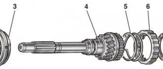
- Then install the main bearing shells in the cylinder block bed in accordance with the marks made during disassembly. Please note that the middle liner 1 is without groove. When installing the liners, their locking lugs must fit into the grooves of the beds. Don't forget to lubricate the bearings with engine oil.
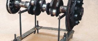
- The next step is installing the crankshaft into the cylinder block.
- Be sure to lubricate the thrust half-rings with engine oil. Pay attention to the grooves of the half rings - these sides of the half rings are installed to the cheeks of the crankshaft.
- Install the steel-aluminum half-ring (it should be white) on the front side of the middle bed (camshaft drive side)…
- ...ceramic metal (it should be yellow) - on the other side of the bed.
- Turn the half rings so that their ends are flush with the ends of the bed.
- Insert the shells into the main bearing caps in accordance with the marks made during disassembly. In this case, the locking antennae of the liners should fit into the grooves of the covers. Lubricate the bearings with engine oil.
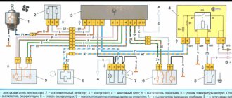
- Install the covers according to the marks. The covers have marks (notches) in accordance with the cylinder number. The exception is the fifth cover, on which two marks are applied, as on the second. The second cover has two threaded holes for the oil receiver mounting bolts. In this case, the cylinder numbers are counted from the camshaft drive side, and the covers are installed with marks 1 towards the generator bracket 2.
- Lubricate the threads and ends of the heads of the cover mounting bolts with engine oil.
- Tighten the bolts and tighten them to the required torque in the following order: first tighten the bolts of the third cover 1, then the second 2 and the fourth 3, then the first 4 and the fifth 5. After tightening the bolts, turn the crankshaft 2-3 turns - it should rotate easily, without jamming.
- To make installation easier, lubricate the oil pump gasket with a thin layer of grease and “glue” it to the block. Remove excess grease.
- Install the oil pump and tighten its mounting bolts.
- To make installation easier, lubricate the rear oil seal holder gasket with a thin layer of grease and “glue” it to the block. Remove excess grease.
- Install the rear oil seal holder and tighten its mounting bolts.
- Insert the connecting rod into the piston according to the marks previously made so that part number 1 on the connecting rod faces in the opposite direction from boss 2 on the piston boss. Then insert the piston pin.
- Install retaining rings on both sides of the pin. Please note that the rings must be clearly installed in the grooves of the piston.
- Install the oil control ring expansion spring onto the piston.
- Install the piston rings using a special puller. If it is not there, install the rings on the piston, carefully opening the ring locks.
- The order of installing the rings is as follows: install the oil scraper ring first (the ring lock should be on the opposite side of the expansion spring lock), then the lower compression ring, and the upper one last.
- Please note that the inscription “VAZ”, “TOP” or “TOP” may be stamped on the rings. With this inscription, the rings are installed upward (towards the piston bottom). If there is no inscription, the oil scraper and upper compression valves can be installed in any position.
- The lower compression ring differs from the upper one except in thickness by the presence of a groove and is installed with this groove down.
- Rotate the rings in the piston grooves and make sure they rotate easily. If any ring does not turn or is stuck, it must be replaced.
- Next, you should rotate the rings on the piston so that their locks are located at an angle of 120° to each other.
- Wipe the crankshaft connecting rod journals thoroughly with a clean cloth.
- Wipe the cylinder mirrors thoroughly with a clean cloth and lubricate them with engine oil.
- Insert the liner into the connecting rod in accordance with the previously made marks so that the antenna of the liner fits into the groove in the connecting rod. After this, lubricate the liner and piston with engine oil.
- Place a special mandrel on the piston to compress the piston rings and carefully lower the connecting rod into the cylinder. It is recommended to first rotate the crankshaft so that the installed piston is at BDC. In this case, the arrow on the piston bottom should be directed forward of the engine (towards the camshaft drive).
- Press the mandrel firmly against the block and use the handle of a hammer to push the piston into the cylinder. If the mandrel does not fit tightly to the cylinder block, the piston rings can break.
- Install the connecting rod lower end onto the crankshaft journal.
- Insert the liner into the connecting rod cap in accordance with the previously made marks so that the tendril of the liner fits into the groove in the cap. After this, lubricate the liner with engine oil.
- Install the connecting rod cover. In this case, the cylinder numbers on the cover and the lower head of the connecting rod must be on the same side.
- Screw in the cover fastening nuts and tighten to the required torque. Install the remaining pistons in the same way.
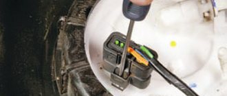
- Insert the oil level sensor into the cylinder block. If necessary, rotate the crankshaft so that the counterweight of the shaft does not interfere with inserting the sensor. Then tighten the sensor mounting bolt.
- Install the oil receiver and tighten the three bolts securing it.
- Apply sealant to the flywheel mounting bolts. Install the flywheel, lock plate and tighten the flywheel mounting bolts.
- For ease of installation, apply a thin layer of grease to the surface of the block and “glue” the oil pan gasket to it.
- Install the oil sump and tighten its mounting bolts. Next, the engine is assembled in the reverse order. To install the cylinder head and camshaft drive belt, see “Replacing the camshaft drive belt and tension roller.”
Well-detailed algorithm for replacing the rear strut liner
So:
- the rack is held in place by one large bolt that needs to be unscrewed;
- at the place where the rear pillar is attached in the area of the cargo compartment, there is a safety cap, which also needs to be removed;
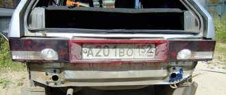
VAZ 2110 strut liner
- The top mount of the rack is held in place by a nut that needs to be unscrewed.
Note. Before unscrewing the rod nut, it must be firmly fixed to avoid idle turns.
- the main washer of the rack is located in the upper part of the pillow; it must be removed;
- after which you need to remove the rear wheel;
- after removing the wheel, the rear shock absorber will open, which will need to be moved down;
VAZ 2110 racks and liners
- next to the support washer there is a lower rack cushion, which also needs to be removed;
- the cover, compression buffer, safety cover, together with the rear strut spring must be removed;
- the shock absorber is enclosed in the niche of the rear installation wheel, from where it must be carefully removed;
- The shock absorber cushions are changed only if they have lost their previous degree of elasticity or have breaks;
- the rear shock absorber strut contains a damping boot, which is also subject to complete replacement;
- before replacing the damping boot, you must first remove it from the tire;
- if during operation the compression stroke buffer has changed from a serviceable state to a faulty state, it is necessary to completely or partially replace it;
- if the insulation gasket fails, it must also be replaced;
- it is necessary to carefully inspect the strut spring and if there is any mechanical damage or at least one of its turns is incorrectly tightened, then there is a need for a complete replacement;
- Assembly of the rack is carried out strictly in the reverse order of disassembly.
Note. During assembly, it is imperative to secure the gasket with tape so as not to disturb its required spatial configuration.
In what cases does it become necessary to repair or replace the strut liner:
- when a car moves over a hole, even the smallest one, the sound of a rumble is clearly heard in the area of the rear pillar;
- The rear of the car behaves extremely unstable, swaying from side to side.
From a practical point of view, the liner extends the final life of the rack and increases its practical effectiveness.
Assembling a VAZ-2110 car engine
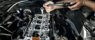
We assemble the engine in the reverse order of disassembly.
Before assembly, we inspect all engine parts.
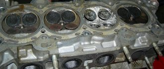
On the VAZ-2112 engine, before installing the upper main bearing shells, use an aerosol carburetor cleaner to clean the nozzles to cool the pistons.
We install liners in the main bearing caps without grooves on the inner surface.
In the first, second, fourth and fifth beds of the cylinder block we install liners with grooves, and in the third bed - a liner without grooves (the same as in the cover)
Lubricate the bearings with engine oil and place the crankshaft in bed.
We insert thrust half-rings lubricated with engine oil into the grooves of the third main bearing support.
The surfaces of the half rings with anti-friction coating (grooves are made on them) should face the cheeks of the crankshaft.
We install the main bearing caps in accordance with the marks marked on their outer surface (the caps are counted from the timing belt drive side).
In this case, the locks of the upper and lower shells of each main bearing must be located on the same side.
Marks on the main bearing caps
Tighten the cover bolts to the specified torque.
When assembling the connecting rod and piston group, it is necessary that the piston pin, lubricated with engine oil, enters the piston hole with pressing force from the thumb and does not fall out of the piston when the pin is in a vertical position.
We install the rings on the pistons and arrange them as follows:
— we orient the upper compression ring lock at an angle of about 45° to the piston pin axis
- lock of the lower compression ring - at an angle of 180° to the axis of the lock of the upper ring.
— oil scraper ring lock – at an angle of 90° to the axis of the upper compression ring lock.
We install the lower compression ring with the groove (“scraper”) down. If the ring is marked “TOP” or “TOP”, place the ring with the mark facing up.
When installing the oil scraper ring, place the expander joint on the side opposite to the ring lock.
Before installing the parts, lubricate the cylinders, pistons with rings and connecting rod bearings with engine oil.
We install the pistons with connecting rods into the cylinders, squeezing the piston rings with an adjustable bushing.
When installing pistons into cylinders, the arrow on the piston bottom must face toward the timing drive.
Arrow location on the piston of VAZ-2110, -2111 and -2112 engines
When installing connecting rod caps, the numbers on the connecting rods and caps must be on the same side.
Further assembly is carried out in the reverse order of disassembly.
Fastener tightening torques when assembling the engine:
Nut of the stud securing the intake and exhaust manifolds 20.87–25.77 Nm (2.13–2.63 kgf∙m)
Tension roller nut 33.23–41.16 Nm (3.4–4.2)
Camshaft bearing housing stud nut 18.38–22.64 Nm (1.87–2.31 kgf∙m)
Camshaft pulley mounting bolt 67.42–83.3 Nm (6.88–8.5 kgf∙m)
Screw for securing the housing of auxiliary units 6.66–8.23 Nm (0.68–0.84 kgf∙m)
Nut for fastening the outlet pipe of the cooling jacket 15.97–22.64 Nm (1.63–2.31 kgf∙m)
Main bearing cap mounting bolt 68.31–84.38 Nm (6.97–8.61 kgf∙m)
Oil sump mounting bolt 5.15–8.23 Nm (0.52–0.84 kgf∙m)
Connecting rod cover bolt nuts 43.32–53.51 Nm (4.42–5.46 kgf∙m)
Flywheel mounting bolt 60.96–87.42 Nm (6.22–8.92 kgf∙m)
Coolant pump mounting bolt 7.64–8.01 Nm (0.78–0.82 kgf∙m)
Crankshaft pulley mounting bolt 97.9–108.78 Nm (9.9–11.1 kgf∙m)
Bolt for fastening the supply pipe of the coolant pump 4.17–5.15 Nm (0.425–0.525 kgf∙m)
Nut for fastening the exhaust pipe of the muffler 20.87–25.77 Nm (2.13–2.63 kgf∙m)
Additional muffler flange mounting bolt 15.97–22.64 Nm (1.63–2.31 kgf∙m)
Nut securing the clutch cable to the bracket 14.7–19.6 Nm (1.5–2.0 kgf∙m)
Bolt securing the cushion of the left and right supports of the power unit to the bracket 20.87–25.77 Nm (2.13–2.63 kgf∙m)
Nut of the stud securing the cushion of the left and right supports to the power unit brackets 34.0–51.9 Nm (3.47–5.50 kgf∙m)
Bolt securing the left power unit support bracket to the gearbox housing 34.0–51.9 Nm (3.47–5.50 kgf∙m)
Bolt securing the bracket of the right support of the power unit to the cylinder block 20.87–25.77 Nm (2.13–2.63 kgf∙m)
Nut of the stud mounting the rear support cushion of the power unit with the VAZ-2110, -2111, -21114 engine to the body 34.0–51.9 Nm (3.47–5.50 kgf∙m)
Bolt securing the cushion to the rear support bracket of the power unit with the VAZ-2110, -2111, 21114 engine 58.8–78.4 Nm (6.0–8.0 kgf∙m)
Bolt of fastening to the cylinder block of the bracket of the front and rear supports of the power unit with the VAZ-2112, -21124 engine 34.0–51.9 Nm (3.47–5.50 kgf∙m)
Bolt (nut) for fastening the rod of the front and rear support of the power unit with the VAZ-2112, -21124 engine 34.0–51.9 Nm (3.47–5.50 kgf∙m)
Bolt securing the oil receiver to the main bearing cover 8.33–10.29 Nm (0.85–1.05 kgf∙m)
Bolt securing the oil receiver to the pump 6.86–8.23 Nm (0.7–0.84 kgf∙m)
Oil pump mounting bolt 8.33–10.29 Nm (0.85–1.05 kgf∙m)
Oil pump housing mounting bolt 7.2–9.2 Nm (0.735–0.94 kgf∙m)
Oil pump pressure reducing valve plug 45.5–73.5 Nm (4.64–7.5 kgf∙m)
Oil filter fitting 37.48–87.47 Nm (3.8–8.9 kgf∙m)
Oil pressure warning lamp sensor 24–27 Nm (2.45–2.75 kgf∙m)
Carburetor mounting nuts 12.8–15.9 Nm (1.3–1.6 kgf∙m)
Cylinder head cover nut 1.96–4.6 Nm (0.2–0.47 kgf∙m)
Source
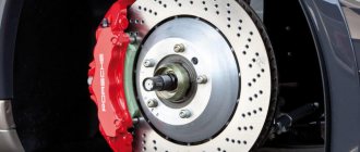
Insert markings and replacement procedure:
- After the first grinding, it is necessary to install liners with the size indicated on the marking of 0.25 mm.
- After the second - half a centimeter.
- After the third procedure - 0.75
- The fourth (last, it is no longer recommended to grind the crankshaft) - 1 centimeter.
The only exceptions are Moskvich and Gazy, which can be sanded an additional two times; for them two liners of 1.25 and 1.50 millimeters come out.
Installation is carried out in the same order, do not forget to tighten the screws more tightly so that they do not come loose after a long run (if manual force is not enough, it is better to use a torque wrench). If you doubt whether, after reading the instructions, you can replace the liner yourself without removing the engine, video lessons with a visual demonstration will help you evaluate whether this type of repair is worth undertaking.
Main signs for dismantling the cylinder head
The manufacturer did not provide any regulations for replacing auxiliary parts of the cylinder head, but there are some signs that will still require dismantling it.
- Presence of mechanical traces on the cylinder head.
- The presence of engine oil or antifreeze leaks at the junction of the cylinder head with the block.
- If white steam comes from the exhaust pipe , this will mean that antifreeze has got into the cylinders and there is no way to do this without removing the cylinder head.
- Emulsion foam on the expansion tank cap indicates exhaust gases entering the cooling system.
- in the coolant - this indicates that the system is not tight.
- on the engine oil dipstick , which tells us that there are traces of antifreeze (antifreeze) in the oil. The work will require removal of the cylinder head.
Tools
To repair a VAZ 2110 engine without a service station, you will need serviceable tools. It is prohibited to use keys that do not fit the size and keys with worn edges.
The handles of the tools used must be plastic or wooden with a smooth and sanded surface. Tools with wooden handles should be reinforced with metal rings - this will prevent the tool from splitting when unscrewing engine elements.
Schematic cross-sectional representation of the engine.
Knocks in the engine
It is not uncommon for even ordinary knocking sounds in the engine to become the cause of its complete failure. Therefore, be careful if you suddenly hear extraneous knocking noises coming from under the hood.
A knock in the engine almost always indicates serious problems, so it is not recommended to get to the service center on your own. Call a tow truck or cling to someone with a rope to get to a service station or garage to determine the cause of the sounds.
The knocking noise can be caused by various components of the 8-valve and 16-valve engines installed on the VAZ 2110.
| Source of knocking | What you need to know |
| Main bearings | This is a dangerous type of knocking. You need to immediately stop the engine and tow it to the service station or garage. The knock is low-pitched and comes from the bottom of the crankcase. As the load increases or the speed increases, the noise increases; the knocking sound is often accompanied by a drop in oil pressure. |
| Connecting rod bearings | No less dangerous type of knock. You need to stop quickly. Get to the garage or car service only in tow. This sound is ringing, metallic, medium in tone, rhythmic. As the load on the engine increases, the knocking noise increases, but disappears completely when the spark plugs are turned off. |
| Piston pins | A less dangerous knocking option, in which you can get to the service center under your own power, but with minimal engine load. The sound is rhythmic, high-precision, and has a strong metallic tint. It comes from the engine in any operating mode, and intensifies with increasing loads. When I turn off the spark plugs, the sound goes away completely. |
| Worn pistons and cylinders | The knocking does not pose a danger to the engine. If the engine load is light, you can get to the service center or garage under your own power. The sound is similar to the clinking of clay dishes, and is especially audible on a cold engine. When the engine warms up the sound disappears |
| Valves | This is not a dangerous type of knocking in the engine, allowing you to get to the garage or car service station under your own power. Against the background of a dull noise, a metallic knock is heard, which is best heard at medium and low crankshaft speeds from the cylinder head above the valves. This type of knocking noise occurs due to a breakdown of the hydraulic compensators, which should be replaced to eliminate the problem. |
| Detonation knocks | Potentially dangerous to the engine if ignored and nothing is done. Sometimes they lead to the need for major engine repairs or replacement. If you do not delay repairs, knocking can be eliminated by simply replacing the knock sensor. Without overloading the engine, you can get to the garage or service station under your own power. The sound is ringing, metallic, and comes from the engine mainly when accelerating. The cause of knocking is a malfunction of the knock sensor, low-grade fuel and engine overload due to early upshift. It is necessary to replace the sensor and add additives to the fuel to remove carbon deposits inside the combustion chamber and on the valves |
Any knocking noise does not bode well, even if it is the sound from valves or worn pistons. Do not delay in eliminating the causes of noise, otherwise repairs will cost much more.
Engine disassembly was discussed in the article - “Engine Disassembly”
Defects of engine parts were discussed in the article - “Engine Defects”
In this article we will look at the main points of assembling the VAZ-2112 engine.
Before assembly, all engine parts must be washed and inspected.
Before installing the upper main bearing shells, use an aerosol carburetor cleaner to clean the nozzles to cool the pistons.
Install liners in the main bearing bed.
In this case, the fixing protrusion of the liner should fit into the groove of the bed.
Install liners with grooves in the first, second, fourth and fifth beds (counting from the camshaft drive), and without a groove in the third.
Lubricate the bearings with engine oil
Lubricate the crankshaft journals with engine oil and place the shaft in the bed of the main bearings.
We insert thrust half-rings lubricated with engine oil into the grooves of the third main bearing support.
The surfaces of the half rings with anti-friction coating (grooves are made on them) should face the cheeks of the crankshaft.
We turn the half rings so that their ends are flush with the ends of the bed.
We install the main bearing caps in accordance with the marks marked on their outer surface (the caps are counted from the timing belt drive side).
In this case, the locks of the upper and lower shells of each main bearing must be located on the same side.
We tighten the bolts securing the covers without tightening them
Marks on the main bearing caps
Tighten the cover bolts to a torque of 69-84 Nm (6.9-8.4 kgf m).
First tighten the bolts of the third cover, then the second and fourth, then the first and fifth.
After tightening the bolts, turn the crankshaft - it should rotate easily, without jamming.
We measure the axial clearance of the crankshaft.
It should be in the range of 0.06-0.26 mm.
If the gap exceeds 0.26 mm, replace the thrust half-rings
To measure the axial clearance of the crankshaft, install the indicator so that its leg rests against the shaft flange.
Move the crankshaft as far as it will go from the indicator and set the indicator to 0.
Move the crankshaft in the opposite direction.
The indicator will show the gap size.
A steel-aluminum half-ring is placed in front (on the crankshaft pulley side), and a metal-ceramic half-ring is placed in the back.
Rings are manufactured with a nominal thickness and an increased thickness of 0.127 mm.
If the axial clearance of the crankshaft exceeds 0.35 mm, one or both half rings are changed (nominal clearance is 0.06-0.26 mm).
Using a mandrel, press the crankshaft rear oil seal into the holder until it stops.
We glue the holder gasket to the oil seal holder with grease for ease of installation
Lubricate the working edge of the oil seal with engine oil.
Lubricate the crankshaft flange with engine oil.
We put the oil seal with a holder on the crankshaft flange and carefully fill the working edge of the oil seal with a pointed stick
Slide the holder with the oil seal along the flange until it stops and tighten the fastening bolts
Adjust the holder so that its top plane coincides with the plane of the block
Tighten the six holder mounting bolts
We prepare the oil pump for assembly.
We press the front crankshaft oil seal into the pump housing.
Lubricate the working edge of the oil seal with engine oil
Lubricate the oil pump gears with engine oil by pouring oil through the oil pickup hole.
We turn the oil pump gears several times using the protrusions of the drive gear.
Rotate the oil pump drive gear so that the lugs on the drive gear align with the flats on the crankshaft.
Flats on the crankshaft
We glue the sealing gasket to the pump with grease for ease of installation.
Place the pump with the oil seal onto the crankshaft up to the seat on the shaft. Then, using a sharpened stick made of soft wood, carefully tuck the working edge of the oil seal onto the shaft journal.
Carefully slide the oil pump along the shaft until it stops and tighten the mounting bolts
Adjust the position of the pump so that its upper plane coincides with the plane of the block.
Tighten the six fastening bolts with a torque of 8.5-10.0 Nm (0.85-1.0 kgf m).
When assembling the connecting rod and piston group, it is necessary that the piston pin, lubricated with engine oil, enters the piston hole with pressing force from the thumb and does not fall out of the piston when the pin is in a vertical position.
We install the rings on the pistons and arrange them as follows:
— we orient the upper compression ring lock at an angle of about 45° to the piston pin axis
- lock of the lower compression ring - at an angle of 180° to the axis of the lock of the upper ring.
— oil scraper ring lock – at an angle of 90° to the axis of the upper compression ring lock.
We install the lower compression ring with the groove (“scraper”) down. If the ring is marked “TOP” or “TOP”, place the ring with the mark facing up.
When installing the oil scraper ring, place the expander joint on the side opposite to the ring lock.
Wipe the cylinder mirrors
We wipe the connecting rod journals of the crankshaft
Lubricate the mirror of the first cylinder with engine oil
Lubricate the mandrel for installing the pistons
Lubricate the piston of the first cylinder
We separate the ring locks as indicated above
We insert the liner into the lower head of the connecting rod. The protrusion on the liner should fit into the groove of the connecting rod head
We insert the liner into the connecting rod cover so that the protrusion on the liner fits into the groove of the connecting rod cover
When installing pistons into cylinders, the arrow on the piston bottom must face toward the timing drive.
We insert the piston assembly with the connecting rod into the mandrel.
Direct the arrow on the piston towards the oil pump and slowly push the piston with the wooden handle of a hammer
We control the correct position of the connecting rod bearings.
Lubricate the bearings and install the connecting rod cover in accordance with the markings.
The caps on the connecting rods are installed so that the cylinder numbers on the cap and connecting rod are located on the same side
We tighten the nuts securing the cover. Install and tighten the caps of the remaining connecting rods in the same way.
Tighten the connecting rod cap nuts with a torque wrench to a torque of 44-54 Nm (4.4-5.4 kgf m).
Before installing the flywheel, lubricate the threads of the flywheel mounting bolts with a thin layer
Install the flywheel so that the mark on the flywheel is opposite the connecting rod cap of the fourth cylinder, since the mounting bolts are located asymmetrically
Install the lock washer and tighten the flywheel
Tighten the flywheel mounting bolts to a torque of 62-89 Nm (6.2-8.9 kgf m), holding the flywheel from turning
We will consider further engine assembly in the continuation of this topic.
Instructions for removing the bearing from the crankshaft
In every car service, in order to remove any of the several dozen bearings that are in the car, there is always a pressing tool, a puller or any other special device. But in our case, when everything is done in an ordinary garage with your own hands, the car enthusiast has to make devices with his own hands or use improvised means. There are 2 ways to remove the ball bearing from the crankshaft seat in a garage.
Method No. 1
If the bearing is not seated in the rear wall all the way, then it can be removed from the inner race using an inertial hook made by yourself. In order to make it you will need:
- a piece of reinforcement or rod (D = 6-8 mm, L = 300-400 mm);
- a metal cylinder with a through hole, d larger than the selected rod (a hub, a massive sprocket or any other similar object may be suitable).
Making the device:
- One of the ends of the reinforcement is bent at an angle of 900, and the length of the bend should be about 10 mm.
- A metal cylinder is placed on one side of the rod.
- On the other hand, a section is welded and a T-shaped tip is made on it.
In order to remove the bearing with such a homemade device, the rod is inserted into the inner race of the bearing and secured with a bend. When the load moves with acceleration, the T-shaped tip is struck. In order to remove evenly, with each blow the rod must rotate around its axis.
On video: How to press a bearing out of a blind crankcase in 3 minutes?
Method number 2
This method can be used to remove the crankshaft bearing; this can be done using a metal cylinder or bolt (with an approximate diameter of 14.5 mm) so that it fits into the hole in the inner race with minimal clearance. An entry that is too loose or too tight will not work. Removing the crankshaft bearing:
- Lubricant (such as “Solidol”) is placed into the cavity behind the bearing through the hole.
- A rod is inserted into the inner cage and hammered in until the rod is completely immersed.
- Add more grease, and under the influence of its pressure, the bearing is squeezed out of the crankshaft seat.
A crankshaft is a part (or assembly of parts) of complex shape that has journals for attaching connecting rods, from which it receives forces and converts them into torque. An integral part of the crank mechanism.
Disassembly and repair of the VAZ 2110 engine
Video on overhaul and engine assembly of a VAZ 2112 car, as well as detailed instructions with photo support for disassembling a VAZ 2110 engine.
Repairing a VAZ 2110 engine, like any other car model, is not an easy job, but it can still be done. If you know even a little about technology, you will be able to do it. To carry out repairs, you must at least disassemble the engine. We bring to your attention a hint on how and in what sequence to perform such work.
History of creation
The VAZ 2112 hatchback model was produced since 1999, becoming the successor to the 2110 sedan and 2111 station wagon. The “Twelfth” became a close analogue of the famous tenth model, but had a slightly shortened body. As planned by the manufacturers, the 2112 was supposed to combine all the advantages of the “ten” and “eleven”, so the five-door hatchback was chosen as the body type.
VAZ-2112 Pre-production (1994)
The 12th model began to be mass produced in 2000; it lasted 8 years on the assembly line. Unlike the sedan and station wagon of the tenth series, the assembly of the “dvenashka” was not transferred to the Ukrainian ones.
Although the twelfth model was positioned as an improved “ten”, the improvements here are very conditional and not always obvious. Therefore, the difference between these two models is not too big. AvtoVAZ designers continued to look for new solutions, as a result of which other lines and modifications appeared, which also have both their pros and cons.
Detailed instructions for disassembling and repairing the VAZ 2110 engine:
2. Remove the clutch from the engine.
3. Remove the tension roller, camshaft drive belt and spacer washer, which is installed under the tension roller.
4. Remove the toothed pulley from the camshaft.
5. We unscrew four bolts, three of which attach the water pump. Unscrew the fastening nut on the rear cover of the camshaft drive belt and remove the cover.
6. To remove the water pump, insert a screwdriver between the block and the flange of the pump housing and thus move it from its seat. After completing these operations, remove the water pump.
7. Remove the head from the cylinder block.
8. Unscrew the bolts (there are 16 of them) securing the oil sump, then remove it together with the gasket.
9. Unscrew the bolts (there are 3 of them) securing the oil receiver and remove it. Please note that there are spring washers under the bolt heads.
10. Unscrew the bolt in the oil sump that secures the oil level sensor. Don't forget that there is a spring washer under the bolt head. We remove the sensor from the cylinder block; if necessary, you can rotate the crankshaft so that its counterweight does not interfere with removing the sensor.
11. Then rotate the crankshaft so that the piston that is being removed hits BDC (bottom dead center). It is necessary to unscrew the two fastening nuts to remove the connecting rod cover.
12. Now remove the connecting rod cover. In cases where it is difficult to dismantle the cover, you can first remove it with light blows of a hammer. It may be that the cylinder number on the cap will not be visible, in which case the cap should be marked with the cylinder number.
13. Using the handle of a hammer, push the connecting rod inside the cylinder, then carefully remove the piston and connecting rod from the cylinder. During the process, you need to make sure that the lower head of the connecting rod does not touch the cylinder mirror, since this can damage it. We remove the remaining pistons in the same way.
14. If you need to remove the piston from the connecting rod, then mark it with the cylinder number so as not to confuse them when installing them. There should also be a cylinder number on the connecting rod: if it is not visible, then we mark the connecting rod as well.
16. Unscrew the bolts (there are 6 of them), remove the crankshaft rear oil seal holder and the gasket. Remember that there are spring washers under the bolt heads.
17. Remove the toothed pulley from the crankshaft. If the key does not fit tightly in the groove of the shaft elbows, be sure to remove it so that it does not get lost.
18. Unscrew the six bolts, under the heads of which there are spring washers, and remove the oil pump and gasket.
19. We unscrew the mounting bolts on the five covers (each with 2 bolts) of the main bearings.
20. Remove the covers.
21. Remove the crankshaft of the VAZ 2110 car.
22. We remove the crankshaft thrust half-rings on the middle support.
23. If you do not plan to replace the liners, then as you remove them, remove them from the block beds and from the main bearing caps.
24. On the non-working side we mark the liners relative to the beds and covers.
25. If there is a need to remove the engine mounts and generator brackets, unscrew the bolts (3 pieces) securing them and remove the water pump supply pipe by unscrewing its fastening.
26. Remove the piston rings using a special puller. If there is no such device, then remove the rings from the piston by carefully releasing the ring locks.
27. Remove the oil scraper ring expansion spring from the auto engine piston.
28. Remove the retaining rings that hold the piston pin on both sides of the piston. There are recesses in the piston bosses for easy removal of the rings.
29. Using a suitable mandrel, push the pin out of the piston, then remove the piston from the connecting rod.
30. Remove the liners from the connecting rod and its cover. If they remain on the crankshaft, remove them from the shaft. If replacement of the liners is not required, then as they are removed, we mark them with respect to the numbers of the covers and connecting rods.
This completes the process of disassembling the VAZ 2110 engine. Good luck with the completion of the renovation.
Detailed video lesson: engine assembly
Video about overhaul of VAZ internal combustion engine:
Our mechanics
| Viktor Nikolaevich | Vasily Ivanovich |
| Working with engines since 1979. Experienced senior mechanic. | Senior electrical engineer. |
The engine is the heart of the car. If you want to be sure of the quality of repairs, sign up for diagnostics and come to our car service center! Our experts will advise you on all issues related to the operation of the Lada 2110 engine.
We guarantee high quality services and reasonable prices!
Work resource
The working life of the VAZ engine is 200 thousand km. Next, the car owner has to put the engine in for major repairs. The timing belt needs to be checked every 50 thousand kilometers. According to experienced car owners, it is because of a broken circuit that the valves bend.
The engine does not like overheating, which means it does not like the lack of oil. Car owners should carefully monitor the presence of lubricant inside the engine. Without oil, the VAZ21126 will overheat greatly, which means the engine’s already short lifespan will become even shorter.
The working life of the chain may be less than the life of the motor itself. But a broken timing belt takes valves and pistons with it. This disease was not present on VAZ 21124 engines. But such engines were installed only on Standard class Priors, that is, cheap modifications of domestically produced cars.
Similar article: Correctly changing engine oil in a car engine
Other reasons that affect the life resource:
- fuel quality. The operating book indicates the brand of fuel that the engine requires. Do not underestimate the figure under any circumstances;
- quantity and quality of oil. Experienced mechanics do not recommend pouring or adding lubricant if the car owner changes the oil himself. Do everything strictly according to the level. Such engines love semi-synthetic or fully synthetic lubricants.
Following the rules described above, the motor can last the stated 200 thousand kilometers.
Attention! Pour new oil strictly into the filler neck. You can use a funnel for the procedure.