Device
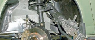
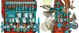
The working pair of the steering gear is a globoidal worm and a double-ridge roller. A worm pressed onto a hollow shaft is installed in the steering gear housing on two tapered roller bearings.
To ensure the reliability of the connection between the shaft and the worm, a keyway is made and splines are cut on the worm shaft. A double-ridge roller is in constant engagement with the worm.
Its annular grooves located inside provide a working surface for a double-row ball bearing. It is mounted on an axis, which is mounted in the head of the bipod shaft.
This shaft rotates in two bearings at once: a bronze bushing pressed into the crankcase and a cylindrical roller bearing. This element is installed in the crankcase cover on the side of the steering gearbox.
The shaft head shank fits into the groove of the adjustment screw. It is screwed into the crankcase cover on the side. The adjustment screw is secured with a pin and a lock washer, which are pressed into the cover. The mechanism is closed with a nut and cap.
With its upper end, the steering shaft enters the bearing, rotating on it. The bearing is pressed into the column housing. The bearing spacer is prevented from moving by a special spring.
Steering control of a UAZ car
Device
The steering system of cars consists of a steering mechanism, a shaft with a steering wheel, a bipod and steering rods. The design of the steering mechanism is shown in Fig. 103. The working pair of the steering mechanism is a globoidal worm and a double roller. The steering gear ratio (average) is 20.3. The worm pressed onto the shaft is installed in the steering gear housing on two tapered roller bearings. The bearing tension is adjusted with thin paper shims placed under the lower crankcase cover.
A double roller is attached to the steering bipod shaft, one end of which rests on a bronze bushing and the other on a cylindrical roller bearing (in the side cover of the crankcase).
The gap in the engagement of the roller with the worm is adjusted by the axial movement of the bipod shaft with a screw installed in the side cover of the crankcase. When the shaft moves, the distance between the axes of the roller and the worm changes and the gap in the engagement changes. A steering bipod is installed on the splined conical end of the bipod shaft, tightly tightened with a nut. The steering shaft at the top rests on an angular contact ball bearing located in the steering column tube. A steering wheel 20 with a diameter of 425 mm is attached to the end of the shaft. To seal the bipod shaft and the worm shaft, oil seals are pressed into the crankcase.
If faults are detected in the steering, it is necessary to check not only the steering, but also the components that affect its operation: wheel hubs, brakes, front springs; You should also check the correct alignment of the front wheels and the air pressure in the tires.
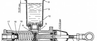
Steering rods. On the UAZ-451M car, the steering linkage linkage is located behind the front axle, and on the UAZ-452 car - on the front. Both rods are equipped with tips in which pins 2 with ball heads are installed. The tips are not adjusted, since the springs 6 contained in them automatically eliminate gaps that appear during wear. Rice. 1. Steering mechanism: 1— steering bipod; 2 — steering gear housing; 3— lower crankcase cover; 4 - adjusting shims for worm bearings; 5 - double roller; 6 - worm; 7 and 8 - worm bearings; 9—filler plug; 10 — roller bearing; 11 — lock washer of the adjusting screw; 12 — lock nut; 13 — adjusting screw; 14 — side crankcase cover; 15 — drain plug; 16 — bushing; 17 — bipod shaft; 18 — oil seal; 19 — column pipe; 20 — steering wheel; 21 — steering shaft bearing; 22 — steering shaft; 23 — clamping clamp; 24 - roller axis
The longitudinal steering rods of the UAZ-451M and UAZ-452 vehicles are identical in design and differ only in length. These rods have adjustable ball joints. In Fig. 2 shows the longitudinal rod and the parts included in it.
In case of wear of the hinge parts, it is necessary to adjust the tightening of the ball pins as follows: unscrew the plug at the end of the rod, screw it in until it stops, and then unscrew it 12-10 turns and tighten it. Adjust the ball pin at the other end of the rod in the same way. Rice. 2. Longitudinal steering rod: 1 — protective lining clip; 2— protective cover; 3— finger with a ball head; 4 - plug; 5 — finger cracker; 6 - spring; 7 — spring limiter; 8 — grease nipple; 9 — longitudinal steering rod; 10 — trailing rod lever Maintenance
At T0-1: — check the fastening of the steering arms, steering rods and bipod; — lubricate the steering rod joints through four grease fittings. It is necessary to force the lubricant to come out to make sure that it has entered the joint. If the lubricant does not come out, you need to check the serviceability of the grease nipples and replace the faulty ones. If even with a working grease fitting, lubrication does not pass through, then you should unload the hinge or disassemble the connection and eliminate the cause of the failure of lubrication. Through TO-1, carry out the work specified for TO-1, and additionally: - check and, if necessary, tighten the fastening of the steering gear housing; check the condition of the steering linkage joints; — Check the steering wheel play. At T0-2: — tighten the nut securing the steering bipod and the nuts securing the steering gear housing to the longitudinal beam of the frame. Before tightening the crankcase nuts, loosen the stepladder nuts securing the steering column; — check the condition of the steering rod heads and the serviceability of their seals. If necessary, undo the cotter pins and tighten the tie rod pin nuts; — check the fastening of the steering rod arms; check and adjust the steering. Through TO-2, perform the work specified for TO-2 and change the lubricant in the steering gear housing.
To drain oil from the crankcase, unscrew the drain plug from the bottom of the crankcase.
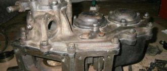
Removing and disassembling the steering mechanism
To repair the steering mechanism, it is necessary to remove it from the car and disassemble it. After disassembling and washing the parts, you need to check their condition (wear) and determine their suitability for further work. If the working pair of steering - worm and mouth, in addition to significant wear on the working surface of the thread, has cavities, dents or peeling, it is replaced with a new one; if there is a noticeable shift in the splines in the connection of the shaft with the bipod, as well as in the case of collapse of the conical surface at the ball pin and bipod, they are also replaced with new ones. The steering mechanism is removed in the following sequence. Unscrew the nut securing the steering bipod and remove the bipod using a puller. Remove the clamp securing the turn signal switch on the steering column, remove the instrument panel and turn signal switch along with the bundle of wires and lower the switch to the floor of the body. Disconnect the signal wire from the coupling.
Remove the signal button, take out the button contact cup, spring and button spring seat.
Unscrew the screws securing the contact plate of the signal button, remove the contact plate along with the insulator and wire and remove the spring. Unscrew the steering wheel mounting nut by 2-3 threads. Using a puller, slide the steering wheel off the shaft cone and then remove it. Remove the steering column mounting stepladder, shims and rubber bushing of the stepladder.
Remove the floor mat, floor seal and steering column seal pressure ring.
Unscrew the bolts securing the crankcase to the frame bracket and remove the steering mechanism (down under the frame). Disassembly of the steering mechanism is performed in the following sequence. Unscrew the crankcase drain plug and drain the oil. Loosen the clamping clamp bolt and remove the column pipe and clamping clamp. Unscrew the locknut of the bipod shaft adjusting screw and remove the lock washer. Remove the crankcase side cover along with the bipod shaft and gasket. Unscrew the adjusting screw from the side cover and remove the shaft. Carefully (without damaging the shims) remove the cover with the sealing ring, spring and spring support washer, gaskets, lower bearing outer ring and cage with rollers. Remove the steering shaft with the worm assembly and the separator with the rollers of the upper bearing from the crankcase. Press the outer ring of the upper bearing and the bipod shaft oil seal out of the crankcase if replacement is required. If there is significant wear, press the bipod shaft bushing out of the crankcase.
If it is necessary to replace the bipod shaft roller, drill out the axle head and press out the axle. After installing the new roller in place, insert the removed axle and weld it to the shaft using electric arc welding.
Remove the spring and expansion ring from the upper end of the steering column tube and press out the bearing. Assembly and installation of the steering mechanism
The steering mechanism is assembled in the reverse order of disassembly. The following must be taken into account. After installing a new worm on the shaft, the end of the shaft should coincide with the end of the groove in the worm; the deviation should not exceed 0.25 mm.
Adjust the worm bearings with paper shims (thick and thin) installed under the steering gear housing cover.
When installing the steering bipod shaft into the crankcase, lubricate the cylindrical part of the shaft and the roller with automotive transmission oil. In the assembled steering mechanism, the runout of the steering wheel shaft on the neck for the ball bearing should be no more than 2 mm. Install the steering column on the car in the reverse order of removal.
In this case, first of all, tighten the bolts securing the steering gear housing to the frame bracket, and then the stepladder nuts securing the steering column to the bracket.
If, after tightening the bolts, a gap appears between the rubber cushion placed on the column tube and the column mounting bracket, it can be eliminated by installing shims. You cannot eliminate the gap by pulling the pipe with a stepladder. This will cause the tube and steering shaft to bend and prevent the bearings from working properly. When the column is moved to the side, the oblong holes in the column mounting bracket allow you to secure it in the new position. If necessary, sawing of holes is allowed. Adjusting the steering gear
If the engagement of the working pair of the steering mechanism is correctly adjusted, there should be no play in the steering wheel when driving in a straight line.
When the steering wheel is turned in any direction by 45° or more, a gap appears in the engagement of the worm with the shaft roller.
With further rotation of the steering wheel, the gap in the engagement, gradually increasing, reaches 30° of rotation of the steering wheel in the extreme positions of the roller. During the operation of the car, the working pair of the steering mechanism, worm bearings and other steering parts wear out. Initially, an increased gap appears in the engagement of the worm and roller, and later, an increased axial movement of the worm appears.
The appearance of increased gaps in the steering mechanism causes a violation of its adjustment and leads to a loss of vehicle safety.
Therefore, you should periodically check the gap in the engagement of the working pair of the steering mechanism and the axial movement of the worm and correct them by adjusting them. It is recommended to check the engagement gap after the car has driven for the first 1000 km, and then at each maintenance service. The condition of the steering mechanism is considered normal and does not require adjustment if the free play on the steering wheel rim in the straight-line position does not exceed 40 mm.
If the steering wheel play is more than specified, then before you begin adjusting the steering, you need to make sure that the steering gear housing mounting bolts are tightly tightened, that the hinge joints are in good condition, and that the bipod is firmly seated on the shaft.
The adjustment begins by checking the axial clearance in the worm bearings. To do this you need to: — put the wheels in a straight driving position; — placing your finger on the lower end of the steering wheel hub and the column pipe, turn the steering wheel in both directions at a certain angle. If the worm bearings are worn, the axial movement of the steering wheel hub relative to the pipe will be felt with your finger. If there is no axial movement, then only the engagement of the working pair of the steering mechanism is adjusted. Adjusting the engagement of the working pair of the steering mechanism. When a gap appears in the engagement of the working pair, it is adjusted by moving the bipod shaft along the axis (without removing the steering from the car). The adjustment procedure is as follows. Place the front wheels of the car in a straight line driving position. Disconnect the tie rod from the steering arm. Unscrew the adjusting screw locknut and remove the lock washer. Use a wrench to turn the adjusting screw clockwise until the gap in the engagement of the worm with the roller is eliminated.
Install the lock washer. If the hole in the washer does not line up with the pin, turn the adjusting screw so that the hole in the washer aligns with the pin.
Screw the locknut onto the screw. Check by shaking the bipod with your hand that the adjustment is correct. The movement of the end of the steering bipod should not exceed 0.3 mm. Install the ball pin into the hole in the bipod, screw on the nut and secure with a cotter pin. Adjusting the worm bearings. After long-term use of the vehicle, gaps appear in the worm bearings in the steering mechanism. To eliminate the axial movement of the worm, you need to remove the steering mechanism from the car and adjust the bearings. Removing the steering mechanism is necessary to check the correctness of the adjustment and measure the amount of force to turn the shaft with the worm.
The adjustment is made by reducing the number of paper gaskets installed under the lower crankcase cover in the following sequence.
Remove the steering mechanism from the car as indicated above. Drain the oil from the steering gear housing, disassemble the mechanism and wash its parts. Install the steering shaft with the worm and bearings into the crankcase. Install the lower crankcase cover, first removing the thin shim. Tighten the cover bolts and secure the steering wheel to the shaft. While turning the steering wheel so that the bearing rollers are in the correct position, check the worm for absence of axial movement. If the play is not eliminated, remove the thick crankcase cover gasket and install the thin one in place.
After eliminating the play, use a tool to check that the bearings are tightened correctly. The force required to rotate the shaft with the worm, applied at a radius of 212.5 mm, should be in the range of 0.22-0.45 kg (without the bipod shaft installed).
There should be no axial play of the shaft in the bearings. The force required to rotate the shaft with the worm engaged with the roller of the bipod shaft (with the steering bipod positioned for straight movement), applied at a radius of 212.5 mm, should be in the range of 0.9-1.4 kg when checking without oil seals In the middle position of the roller (within 45° of rotation of the worm in one direction or another), there should be no gap in the engagement. After adjusting the worm bearings, install the bipod shaft and side cover into the crankcase and adjust the engagement of the worm with the roller. When the gearing is correctly adjusted, the free play on the steering wheel rim (with the wheels stationary) should be within 10-15 mm. Read more: UAZ car brakes - UAZ
Home → Directory → Articles → Forum
Adjusting the steering gear of UAZ loaf
Adjustment operations are carried out to eliminate gaps.
Due to friction forces, they periodically appear between the roller and the worm. To identify the axial clearance of the worm bearings, grasp the crankcase with the palm of one hand. With the other hand, the steering wheel swings alternately in both directions.
If the bearings are worn out, the finger feels the axial runout of the hub relative to the column. In the absence of bearing clearances, only the engagement of the worm with the roller is adjusted.
The procedure for adjusting the roller relative to the worm:
- Remove the steering gear from the vehicle.
- Drain the oil from the crankcase.
- Secure the mechanism in a vice.
- Unscrew the central nut and remove the lock washer from the adjustment screw.
- Unscrew the bolts securing the cover to the side of the gearbox.
- Remove the bipod shaft together with the roller and cover, carefully tapping the end of the bipod shaft with a drift, and separate the gasket.
- Unscrew the bolts securing the lower crankcase cover and remove it.
- Carefully separate and remove the thin paper pad.
- Place the bottom cover in its original place, tighten the bolts, and check the runout of the worm along the longitudinal axis.
- If the runout remains, remove the cover from the bottom again, remove the thick gasket, and replace it with the thin one that was previously removed. It is not recommended to remove more than one gasket.
- The tightening force of the bearings is checked by rotating the worm. If the tightening is correct, a force of 0.22 - 1.45 kgf is felt on the steering wheel. The checking operation is carried out with a torque wrench with the bipod removed.
Repair and service of cars, engines and automatic transmissions
_____________________________________________________________________________
Repair of steering control of UAZ-3962, UAZ-3741 cars
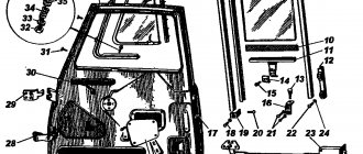
The steering of the UAZ-3962, UAZ-3741 car consists of a worm-roller type steering mechanism with a steering wheel (Fig. 14) and a steering gear (Fig. 16).
Fig. 14. Steering mechanism UAZ-3962, UAZ-3741
a-steering column with cardan joint; 1-bipod; 2-crankcase; 3-bottom cover; 4-adjusting shims for worm bearings; 5-roller; 6-worm; 7,8,29-bearings; 9-plug seal; 10-filler plug; 11-gasket; 12-side crankcase cover; 13-pin; 14-lock washer; 15.35 bushings; 16-shaft bipod; 17-cuff; 18-washer; 19-nut; 20-steering wheel; 21-column; 22- steering shaft; 23-bipod shaft bearing; 24- mesh clearance adjusting screw; 25-cap nut; 26-axis roller; 27-oil seal; 28-wire horn; 30.39-plastic bushings; 31-screw; 32-spacer sleeve; 33-protective washer; 34-hinge; 36-circlip; 37-spring; 38-pin bushing
Rice. 16. Steering gear UAZ-3962, UAZ-3741
1- longitudinal steering rod; 2- longitudinal steering rod lever; 3.6-levers steering linkage; 4.7 - tie rod ends; 5- tie rod
Rice. 15. Steering mechanism UAZ-3741, UAZ-3962 with power steering
1-nut; 2,5,6,19,21,22,35,39 - O-rings; 3-glass; 4.10-thrust bearings; 7-piston-rack; 8-screw; 9-crankcase; 11-injection hose fitting; 12-fitting drain hose; 13-sleeve; 14-cuff; 15-torsion bar; 16.38-pins; 17-ball drive; 18-balls; 20-channel in the crankcase; 23-bipod; 24-nut bipod; 25-protective bottom cover; 26-rings; 27-adjusting washers; 28-bipod shaft support; 29-rollers; 30-shaft bipod; 31-top protective cover; 32-rotor; 33-protective cap; 34-distributor housing; 36-channel in the distributor housing; 37-bolts securing the distributor housing to the crankcase
Removing the steering mechanism of UAZ-3741, UAZ-3962
Removing the steering mechanism of UAZ-3741, UAZ-3962 is carried out in the following order:
— Remove the turn signal switch. — Disconnect the signal wire. — Remove the signal button and contact parts.
— Unscrew the steering wheel fastening nut 2-3 turns and, using a puller, loosen the steering wheel fastening on the steering shaft cone.
— Unscrew the steering wheel nut and remove the steering wheel. On vehicles with a steering column with a universal joint (see Fig. 14a), removal of the steering mechanism is possible without removing the steering column.
Dismantling the steering mechanism of UAZ-3962, UAZ-3741 worm-roller type
Disassemble the UAZ-3741, UAZ-3962 worm-roller steering mechanism in the following order:
— Unscrew the nut and remove the lock washer from the adjusting screw. — Unscrew the bolts securing the side crankcase cover. — Using a light blow of a copper or aluminum drift on the end of the bipod shaft, remove the bipod shaft along with the roller and cover and carefully remove the gasket. — By screwing the adjusting screw into the side cover of the crankcase, remove the side cover and the adjusting screw from the bipod shaft. — Unscrew the bolts securing the lower crankcase cover and remove the cover along with the gaskets, the outer ring of the lower bearing and the separator with rollers. — Take out the crankcase shaft with the worm assembly and the separator with the rollers of the upper bearing. — Press the outer ring of the upper bearing, the steering gear shaft cuff, the bipod shaft cuff and the bipod shaft bushing out of the steering gear housing only if they are replaced.
Assembling the steering mechanism of UAZ-3962, UAZ-3741, worm-roller type
Assemble the UAZ-3741, UAZ-3962 worm-roller steering mechanism in the reverse order of disassembly, taking into account the following:
— In case of replacing the worm when pressing it onto the shaft, it is necessary that the high spline of the worm coincides with the keyway of the shaft. The discrepancy between the end of the shaft and the end of the groove on the worm should not exceed 0.25 mm.
— The roller of the steering bipod shaft should rotate freely by hand. When installing into the crankcase, lubricate the cylindrical part of the bipod shaft and the roller with liquid lubricant.
- Lubricate cylindrical and tapered bearings, outer surfaces of the worm and oil seals with grease. — Tighten the worm bearings and adjust the engagement of the roller with the worm. — The runout of the shaft journal under the ball bearing of the steering column on the assembled steering system should not be more than 3 mm. When checking, the shaft assembly with the worm should rotate easily in the worm bearings.
Repair of steering gearbox UAZ Bukhanka
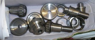
After disassembling the mechanism, wash and inspect the parts.
If you find peeling of the heat treatment layer, cavities, excessive wear, or cracks on the working surfaces of the worm, screw, rack nut, sector shaft, excessive wear, or cracks, they should be replaced immediately. Screw and worm bearings should be replaced with new ones if all adjusting shims are removed to eliminate axial play or if there is damage on the working surfaces of balls, rollers, and rings.
If shells, cracks, nicks, dents are found on the working planes of the roller, bipod shaft, if there is play in the bearings or fit on the axle, it is necessary to drill out its head and remove the roller.
Insert a new roller and axle into the shaft groove. It can be secured using electric welding on the bipod shaft of the old axle - on the side of the drilled head, and on the new axle - on both sides.
Under no circumstances should the roller be allowed to overheat. If you find cavities, dents, cracks, or excessive wear on the planes under the rollers, immediately replace all rings of the sector shaft support with new ones.
If there is noticeable twisting of the splines, the bipod shaft should be replaced. If excessive wear occurs on one side of the crankcase bronze bushing, replace it with a new one. Having pressed a new bushing into the crankcase, iron it with a brooch to a diameter of 35 +0.027 mm.