I looked for the schematic and found it in good quality so it wouldn’t get lost. UAZ–3741, 3909, 3962, 2206
How is the 452 wiper motor connected?
diagnostic connectors OBDII and UAZ / GAZ
I have a 1989 car, originally it had a contactless ignition system. Later it was converted to contact, which in principle I do not regret. And each has its own pros and cons. We’re not talking about them. I had to use the old-style UAZ 3303 wiring diagram, of course, with a carburetor.
The plant immediately warns about the possibility of making changes to the electrical circuit. Since the car is almost 30 years old, there are such changes. I will give several diagrams with contact and non-contact ignition systems for different UAZ vehicles. But since in those days there were no special differences, I consider them similar with some differences.
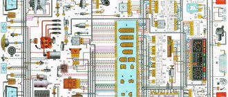
Electrical wiring diagram
The top picture shows a non-contact version of the car's electrical wiring in color; the bottom picture shows an older model.
Old style UAZ 3303 wiring diagram
The electrical circuit of the UAZ 3303 generator shown separately is shown above.
The circuit having an ignition system with contacts is taken from 469. There is a radio receiver on the circuit, this is interesting.
Electrical circuit of UAZ 469 similar to 3303 with contact ignition system
In conclusion, I present another one from an onboard UAZ 33036 that is newer, but not yet fuel-injected.
The integrated microprocessor engine control system (CMPSUD) of passenger-and-cargo utility vehicles, UAZ-3741 and UAZ-3909 vans, UAZ-3962 ambulances, UAZ-2206 buses and UAZ-3303 freight vehicles includes an electronic control unit, sensors, actuating electric mechanisms, and diagnostic control malfunction lamp, wiring harness and diagnostic connector.
CMPSUD diagrams of cars of the UAZ-3741, 3909, 3962, 2206 and 3303 families with UMZ-4213, ZMZ-4091 and ZMZ-40911 engines.
On freight-passenger cars of the UAZ-3741, 3909, 3962, 2206 and 3303 models, depending on the engine and its environmental class, a KMPSUD with the following electronic control units and controllers was installed:
— For cars with the UMZ-4213.10 Euro-2 engine — MIKAS-7.2 control unit 291.3763000-11 — For cars with the UMZ-4213.10 Euro-3 engine — MIKAS M10.3 control unit 574.3763000-03 — For cars with the ZMZ-4091.10 Euro engine -3 - control unit MIKAS-11 825.3763001-01 or BOSCH M17.9.7 0 261 S04 795 - For cars with a ZMZ-40911.10 Euro-4 engine - control unit BOSCH M17.9.7 0261 S06 585 for configuration with a mass air flow sensor and BOSCH M17.9.7 0261 S07 322 for equipment with absolute pressure sensor.
CMPSUD diagram of cars of the UAZ-3741, 3909, 3962, 2206 and 3303 families with UMZ-4213.10 Euro-3 engines and the MIKAS M10.3 control unit 574.3763000-03.
Diagram of the KMPSUD wiring harness for cars of the UAZ-3741, 3909, 3962, 2206 and 3303 families with UMZ-4213.10 Euro-3 engines and the MIKAS M10.3 control unit 574.3763000-03.
The composition of the UMZ-4213.10 Euro-3 engine control system with the MIKAS M10.3 control unit, its sensors and actuators are discussed in detail in a separate material.
CMPSUD diagram of cars of the UAZ-3741, 3909, 3962, 2206 and 3303 families with ZMZ-4091.10 Euro-3 engines and MIKAS-11 control unit 825.3763001-01.
The composition of the ZMZ-4091.10 Euro-3 engine control system with the MIKAS-11 control unit, its sensors and actuators are discussed in detail in a separate material.
CMPSUD diagram of cars of the UAZ-3741, 3909, 3962, 2206 and 3303 families with a ZMZ-4091.10 Euro-3 engine and a Bosch M17.9.7 control unit.
The composition of the ZMZ-4091.10 Euro-3 engine control system with the Bosch M17.9.7 control unit, its sensors and actuators are discussed in detail in a separate material.
Electrical diagram of the CMPSUD of cars of the UAZ-3741, 3909, 3962, 2206 and 3303 families with ZMZ-40911.10 Euro-4 engines and a BOSCH M17.9.7 0261 S07 322 control unit.
The composition, sensors and actuators of the control system of UAZ-3741, 3909, 3962, 2206 and 3303 with ZMZ-40911.10 Euro-4 engines and the BOSCH M17.9.7 control unit are discussed in a separate material.
Designations of components and circuits in the diagrams:
A1 — engine control controller (unit); A2 — electric fuel pump module with level sensor; A3 - instrument cluster or panel; A4 - immobilizer (car anti-theft system - APS); A5 - trip computer; A6 — accelerator pedal module (E-gas); A7 — throttle device with electric drive; B1 - throttle position sensor; B2 - mass air flow sensor; B3 - coolant temperature sensor; B4 - air temperature sensor; B5 - knock sensor; B6 - oxygen sensor No. 1; B7 - oxygen sensor No. 2; B8 - rough road sensor; BP1 — intake air absolute pressure sensor; BP2 - emergency oil pressure alarm sensor; BP3 - air conditioner refrigerant pressure sensor; BR1 — synchronization sensor (crankshaft position); BR2 — phase sensor (camshaft position); BV1 - vehicle speed sensor; F1-F4 - spark plugs for cylinders 1-4; FU1-FU6 - fuse; HL1 - MIL lamp for engine diagnostics; HL2 — IMMO lamp for immobilizer status (ALS unit); GB1 - rechargeable battery; KA1 - main relay; KA2 - electric fuel pump relay; KA3, KA4 - relay for electric fans No. 1 and No. 2 for engine cooling; KA5 - air conditioning compressor clutch relay; L1 – immobilizer transceiver antenna; M1 - electric fuel pump; M2, M3 - electric fans 1 and 2; PF1 - tachometer; PS1 - coolant temperature indicator; TV1, TV2 - two-terminal ignition coil; TV3 - ignition module with two-terminal coils; TV4-TV7 - individual ignition coils; TV8 – four-terminal ignition coil; W1-W4 - high-voltage ignition wires; SA1 - ignition switch; SA2—mass switch; SA3 - air conditioner switch; SA4 — two-channel brake pedal switch; SA5 – clutch pedal switch; XS1 — diagnostic connector; XS2 — nozzle connector; Y1-Y4 — gasoline injectors; Y5 — additional air regulator (idle speed); Y6 — adsorber purge valve; Y7 - electric coupling of the air conditioning compressor; * — the component can be installed as an additional kit.
Central light switch UAZ 469 wiring diagram
The main command vehicle of the armed forces - this is how the UAZ 469 SUV can be described. And indeed, having replaced the GAZ-69 in 1972, it secured this honorable duty for many years, proving the correctness of the design and main components with its endurance and reliability.
Historical reference
Traditionally, the UAZ 469 was produced in two versions:
- Cargo-passenger version – 7 seats and 100 kg of luggage;
- Commander version - 2 seats for passengers and 600 kg of luggage.
For reference: regardless of the version, the UAZ 469 can tow a trailer with a total weight of 850 kg.
Industry standard 1945
According to the old vehicle classification system, in force since 1945, the UAZ 469 was produced under this name, using an alphanumeric name:
- The letter abbreviation UAZ stood for Ulyanovsk Automobile Plant;
- 469 is a serial factory index assigned by the enterprise itself to its models and developments.
For reference: according to the industry standard of 1945, each automobile plant was assigned a specific numbering. For MZMA, which produced Moskvich 408 and 412, these are numbers from 400 to 449, for the Ulyanovsk Automobile Plant these are numbers from 450 to 484, etc.
1966 Industry Standard
Although at the time of the release of the UAZ 469 (1972) a new industry classification system was adopted (industry standard OH 025270-66), the car plant continued to use the name according to the old standard.
However, in 1985, the automaker was forced to change its name in accordance with current requirements:
- the car was assigned a four-digit number - 3151;
- According to the new system, the car can be called in the documentation as UAZ 3151.
For reference: industry standard OH 025270-66 prescribes determining the type of vehicle by engine displacement, length and weight. The first digit indicates the class of the car, the second – the type (truck or passenger car), the third and fourth – the factory model index.
The car plant named all further modifications and new models in accordance with current standards. In particular, the UAZ Patriot, which appeared in 2005, according to the industry classification, received the “correct” designation - UAZ-3163. For greater identification, the factory instructions contained both names.
For reference: the automaker, even in the promotional video for the Patriot model, makes every possible reference to the legendary “ancestor” - the UAZ 469. This model really turned out to be capable of effectively coping with domestic off-road conditions.
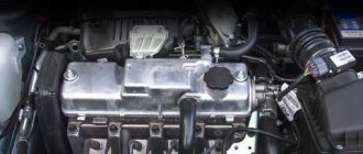
Engine compartment
For many years, the main power unit of the UAZ 469 was the in-line 4-cylinder UMZ-451MI carburetor type. The engine capacity was 2445 cc. cm, power – 75 hp.
With this engine produced by the Ufa Motor Plant, the UAZ 469 lasted on the factory assembly line until 1985.
It was distinguished by a simple single-wire 12-volt ignition circuit, which consisted of (according to the numbering):
- rechargeable battery (AB);
- mechanical ground switch;
- electronic battery charge voltage regulator;
- alternator;
- ammeter on the instrument panel;
- ignition switch (switch);
- ignition breaker contact group;
- directly to the ignition distributor (distributor);
- capacitor built into the distributor;
- ebonite distributor cover with leads for high-voltage wires;
- ignition distributor slider;
- spark plugs;
- high voltage wires from the ignition coil;
- additional coil resistance;
- starter relay;
- directly to the high-voltage ignition coil;
- electric starter.
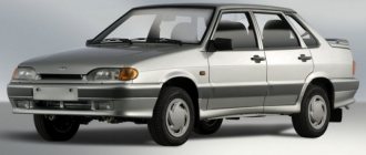
Electrical equipment UAZ 31512
The wiring diagram of the UAZ 31512 is made according to the single-wire principle. This means that consumers have a common negative contact, which is the car body.
The electrical equipment of a car consists of several systems:
- Food;
- Starting and power supply of the power unit;
- Measuring instruments;
- External and internal lighting;
- Light signaling;
- Autonomous heating;
- Windshield cleaning;
- Sound alarm.
IMPORTANT: To prevent fire due to short circuit or overload, electrical circuits are protected by fuses.
Blog about UAZ
To switch the main circuits of the car, a combined ignition switch is used, consisting of a contact part and a mechanical anti-theft device with a lock. When the engine is not running, all consumers are powered by the battery, and after the engine is started - by an alternating current generator with a built-in rectifier unit. When the generator is running, the battery is charged.
Electrical diagram of UAZ-31512.
Electrical diagram of UAZ-31514 and UAZ-31519.
Electrical diagram of UAZ-31519-095 and UAZ-31519-195.
When the engine is idling, the rotation speed of the generator rotor and, accordingly, the supplied current are insufficient to provide power to powerful consumers, such as headlights, a windshield wiper, an electric heater fan, and an alarm system. In this mode, the battery will be discharged.
Location and purpose of fuses for electrical circuits of the on-board network of UAZ-31512, UAZ-31514 and UAZ-31519.
To protect the vehicle's external lighting electrical circuits from overload, a bimetallic fuse 29.3722 or similar is used, which is installed under the instrument panel on the left. Three 10 Amp fuses are installed in the PR103 fuse box, mounted on the partition of the engine compartment. They protect:
No. 1 - circuits of control devices; No. 2 - direction indicator circuits; No. 3 - alarm and sound signal circuits.
Checking the electrical circuits of the on-board network of UAZ-31512, UAZ-31514 and UAZ-31519 under voltage.
Live circuits are checked with a voltmeter and ammeter. The voltmeter is connected in parallel to the device or circuit section being tested. Measurement range 0–15 or 0–25 Volts DC. The negative wire (probe) is connected to ground, the positive wire is connected to consumers or current sources. By the voltage drop, you can determine a malfunction of the supply circuit - a break, oxidation of contacts, etc., as well as a short circuit in the consumer.
To check live circuits, you can also use a test lamp with a power of no more than 3–4 W, designed for a voltage of 12 Volts, for example the AMH12-3 lamp used in the instrument panel.
The ammeter must have an upper measurement limit of at least 10 Amps DC, as well as overload protection. We connect the ammeter in series with the device being tested. The plus of the device is connected to the current source, and the minus is connected to the consumer’s plus. If the current is less than required, then the electrical circuit is faulty, and if it is more, a short circuit has occurred in the consumer.
Warning lamps and measuring instruments
On the front panel of the car there is a block of instruments and warning lamps. It is necessary to control the operation of machine components and mechanisms. Installed on the panel:
- Pointer gauge for fuel level in the tank. Readings are taken from a sensor installed in the left or right tank;
- Coolant temperature gauge. Indicates the temperature in the engine cooling system;
- Oil pressure gauge in the lubrication system of the power unit;
- Voltmeter. Serves to determine the voltage in the on-board network;
- Emergency lamps for oil pressure and fluid in the brake system;
- Warning lamps for direction indicators, parking brake system, low beam headlights, exceeding the permissible coolant temperature.
External and internal lighting
The car is equipped with external and internal lighting. It is necessary to use the machine at night. The exterior lighting scheme includes low/high beam headlights, side lights, and license plate lights. External lighting is controlled by a combination switch.
Internal lighting is made in the form of a interior lamp and a lamp for illuminating the engine compartment. The interior lighting is controlled by a switch mounted on the front panel. You can also read about the UAZ 315195 Hunter.
REFERENCE: Interior lighting includes instrument lighting. The brightness of the backlight is controlled by the combination outdoor lighting switch.
Light signaling
The electrical circuit of the UAZ 31512 includes a light signaling system. This includes direction indicators, brake signals, and a car reversing light. Connection diagram for turn signals on a UAZ 31512 with a RS 950 relay. It is used simultaneously for turn signals and activating the hazard warning lights.
The light signaling is controlled by the following elements:
- Turn switch;
- Stop light button;
- Reversing light switch;
- Hazard switch.
Period from 1965 to 1984
During this period, the automaker equipped its products with electrical components available to the domestic industry. Some of them were known for a long time, others were experimental, as evidenced by videos from previous years, and which had to prove their suitability.
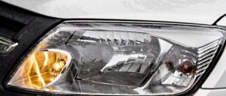
Connection diagram for headlights on UAZ 452 first editions
Lighting control
In particular, the controls and a number of main units migrated from its predecessor, the GAZ-69. Thanks to this, the price of the car remained the same.
On models of the first years of production, a foot light switch was installed, which had several operating modes:
- The first position activated the circuit for switching the low beam headlights and side lights;
- In the second position, the low and high beam headlight circuit was activated.
For reference: Turning on the headlights (low or high beam) led to the turning off of the front side lights.
Foot switch for headlights and parking lights
The modernized light switch has a different operating algorithm:
- The first position supplies power to the side lights only;
- The second position is side lights and low (high) beam headlights.
Caution: This algorithm with non-switchable dimensions is a mandatory requirement for passing MOT. The factory instructions give recommendations for reworking the old circuit, in which it is important not to mix up the contacts of the foot switch.
The most correct option is to replace the old switch with a modern one, which uses only 3 contact groups.
Also, on older versions of the “452” there was no alarm, so in the electrical diagram:
- An RS-57 breaker relay was installed (mounted in the wiring gap from the “+” terminal of the battery to the direction indicator switch);
- The middle contact of the relay closed the indicator light on the instrument panel.
Heater and horn
UAZ 31512 is equipped with an autonomous heater. The circulation of hot air in the cabin is carried out by a fan. The fan motor is started by a switch mounted on the panel. The fan motor has two rotor speeds.
The machine is equipped with a sound signal. It is necessary for the safe use of a car on public roads. Under the influence of electric current, the signal membrane begins to vibrate, producing sound. The signal is controlled by a button located on the steering wheel.
Glass cleaning
The windshield of a UAZ 31512 car is cleaned with electrically driven brushes. The wiper motor has two modes. The windshield wiper system includes an electric washer motor. The system is controlled by a combination switch.
ATTENTION: The electrical diagram includes a socket for connecting trailer wiring.
From the above it follows that the UAZ 31512 equipment consists of several electrical circuits. The wiring is made with multi-colored wires. This makes the repair procedure easier if there is a color scheme.
Wiring diagram for loaf with carburetor engine
To connect electrical appliances to the system of a car with a carburetor, an old-style circuit is used - a loaf designed for UAZ cars produced in 1954 - 1984.
Why might you need a wiring diagram for such a car? The need for instructions for wiring in a car may arise not only if some defect that interferes with the operation of the vehicle is corrected, but also when the wiring is re-installed.
It is worth remembering that there are two circuits for a car with a carburetor engine. The first is a simple one, in which there is no electronic carburetor control unit (this element appeared after 1984 and is not included in the old circuits).
The second is a little more complicated (the connection to the carburetor control unit is taken into account). Such a scheme should be used if it is necessary to connect to the operation of all electronic systems of the car, and not just the ignition and the minimum necessary to drive the vehicle.
To conduct wires according to a simplified scheme, it is enough to stretch a wire from the battery through the toggle switch to the ignition to create a spark, and the second through the relay and button to the starter to make it possible to start the engine.
If the car's generator does not have a voltage regulator built-in, then you need to purchase one and connect it to the system.
What is included in the electrical circuit?
What features do automotive electrics have on old cars produced by the Ulyanovsk Automobile Plant?
Electronic components
The electrical circuit of the UAZ 452 itself is quite simple - single-wire.
By its design, the wiring diagram of a UAZ390995 or other model is characterized by the following solutions:
- The vehicle body is used as the mass.
- Any electrical equipment of the old-style circuit on a UAZ 409 or other model, as well as actuators, are equipped with a negative terminal, which is connected to the car body. According to experts, in general this scheme is imperfect.
According to the operating instructions for electrical equipment, the driver must periodically diagnose the condition of the integrity of the contacts. We are also talking about their oxidation. If the driver notices the presence of oxidation on the terminals, he should treat them using fine-grained sandpaper.
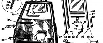
Engine compartment
In this case, the engine compartment is located directly in the passenger compartment in accordance with the design of the car.
Access to the electrical circuit and other mechanisms and assemblies is made from the interior, as a result of dismantling the cover, which:
New modifications
Since 1985 the car has undergone changes. They can even be called quite significant. It is also worth considering that in recent years the electrical circuit of the UAZ 452 has been quite seriously modernized. And the basic equipment itself has become noticeably richer. Now the injector has become a modification for the UAZ Bukhanka. The manufacturer abandoned carburetor systems and released a more economical and modern injector for the UAZ Bukhanka. The electrical equipment of the UAZ has become more progressive.
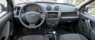
The dashboard has also been transformed. The most noticeable changes were: an additional starter relay, additional resistance in the battery ignition circuit. However, most Bukhanka owners upgrade their vehicle themselves. And the dashboard is the first step to modernizing the interior.
In the basic configuration, the dashboard does not look impressive, so most drivers decide to upgrade its appearance. A solid overlay is installed on the panel, which makes it more visually interesting. This overlay is freely available, and buying it is not particularly difficult. The dashboard in the UAZ 452 is all-metal and does not decorate the interior. Modern panel trim is mostly made of plastic and serves as a good decoration for this car.
Another drawback in the old Loaf is the lack of electric windows. However, power windows can be easily installed yourself. They will fit perfectly into the electrical circuit of the UAZ 452. But neither the installation of window regulators nor their initial absence in the electrical wiring is the main problem of the poor configuration.
Features of electrical equipment
So, what features does the UAZ 452 electrical wiring diagram have? At the time of the start of production, the most difficult moment for the engineers and designers of the enterprise was the search for the highest quality elements and components.
In particular, we are talking about parts for the vehicle lighting system, as well as ignition, which is especially clearly seen in how the car’s cabin is filled:
- control elements for various transport systems;
- control devices for monitoring the condition of components and mechanisms.
External optics
At that time, designers had to resort to many freelance solutions in order to establish mass production of cars.
- The UAZ electrical circuit includes an optics switch, which was borrowed from the GAZ 69. By the way, the latter is the predecessor of the Bukhanka.
- In addition, almost all the optics were borrowed from the GAZ 64 - these are lights, etc.
Ignition system
Period from 1965 to 1984
During this period, the automaker equipped its products with electrical components available to the domestic industry. Some of them were known for a long time, others were experimental, as evidenced by videos from previous years, and which had to prove their suitability.
Lighting control
In particular, the controls and a number of main units migrated from its predecessor, the GAZ-69. Thanks to this, the price of the car remained the same.
On models of the first years of production, a foot light switch was installed, which had several operating modes:
- The first position activated the circuit for switching the low beam headlights and side lights;
- In the second position, the low and high beam headlight circuit was activated.
For reference: Turning on the headlights (low or high beam) led to the turning off of the front side lights.
The modernized light switch has a different operating algorithm:
- The first position supplies power to the side lights only;
- The second position is side lights and low (high) beam headlights.
Caution: This algorithm with non-switchable dimensions is a mandatory requirement for passing MOT. The factory instructions give recommendations for reworking the old circuit, in which it is important not to mix up the contacts of the foot switch.
The most correct option is to replace the old switch with a modern one, which uses only 3 contact groups.
Also, on older versions of the “452” there was no alarm, so in the electrical diagram:
- An RS-57 breaker relay was installed (mounted in the wiring gap from the “+” terminal of the battery to the direction indicator switch);
- The middle contact of the relay closed the indicator light on the instrument panel.
Ignition system
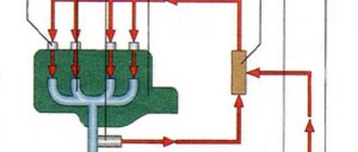
Also on the “452” contact ignition was installed:
- The “+” wire from the battery supplied power to the ignition coil;
- From the coil, the high-voltage wire transmitted the impulse to the breaker (distributor) and further to the spark plugs.
Period from 1985 to 2013
In later modifications, with the advent of injection, some changes were made to the ignition:
- An additional resistance was installed in the “battery-ignition coil” circuit;
- A separate wire from the starter was laid to the coil wire connection terminal (past the additional resistance)
- On later models, an additional starter relay was installed in the circuit.
For reference: UAZ vehicles also have different control devices. Some machines had an ammeter installed instead of a voltmeter. The UAZ 452 wiring made it possible to connect a voltmeter into the wire gap between the battery and the ignition system.
Conclusions: along with the car, the electrical circuit also changed. This factor should be taken into account when carrying out scheduled repair work in order to eliminate emergency situations.
The first copies of the UAZ 452 saw the world in 1965 and forever entered the history of Soviet automobile production. The electrical circuit of the UAZ 452 and even the body structure of this car are trouble-free. The car has become a truly multi-purpose means of transportation. It was used for both military and medical purposes. Over all these years of reliable service, the UAZ 452, or also called Bukhanka, has become simply a cult car for domestic car enthusiasts.
It is especially worth noting the reliable electrical equipment of the UAZ. Over the years of production, the car has undergone many changes. For example, the UAZ wiring diagram has become much more modern and technologically advanced.
troubleshooting
On any domestic car, problems periodically arise in the operation of electrical equipment. If you notice that the UAZ wiring is not working correctly, you need to diagnose it and check all the elements. If there are any malfunctions in the operation of electronic devices, first of all you need to check whether the fuses in the mounting block have burned out. If everything is fine with these elements, but the equipment still does not function, for example, if we talk about optics, then you need to check whether the light bulbs are working. If the lamps themselves are working, it is necessary to test the electrical part using a tester (the author of the video about testing car wiring is Ramil Abdullin).
If the Loaf refuses to start at all, you need to do the following:
- First of all, check the functionality of the battery.
- With the battery charged, use a tester to test the circuit from the coil to the generator; often the reason for the inability to start the engine is breaks in the wiring. If there are breaks, the wires should be changed. If there is oxidation on the contacts, they should be cleaned.
- Starting the power unit will be impossible if there is no spark. To diagnose the presence of a spark, remove the high-voltage cable from the spark plug and bring it to the body. When you try to start the engine, a spark should jump between the cable and the body.
- If there is no spark, the problem may be carbon deposits and deposits on it. By the way, carbon deposits are often the cause of unstable engine operation and tripping. To get rid of such a malfunction, it is advisable to clean the spark plugs; step-by-step instructions for this process are presented here.
Wiring diagram for injection UAZ (loaf)
One of the most common problems with domestic cars is the breakdown of any electrical devices; an electrical diagram will help you figure this out. The only solution to this problem will be to check the condition of the fuses. The topic of today's article will be the electrical circuit of a UAZ Bukhanka car on an injector-type engine.
UAZ Bukhanka
So, this article provides answers to these fairly common questions:
- What is the electrical circuit on a UAZ Bukhanka car with an injector type engine?
- How does the electrical circuit of the UAZ Bukhanka car work?
- Where are the fuses located on a UAZ Bukhanka car with an injector type engine?
- Repair of the mounting block.
basic information
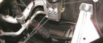
Fuses in a UAZ Bukhanka car are located in a special mounting block, which in turn is located in the air inlet box on the left side of the vehicle.
The mounting block includes all the most important sections of electronic circuits, while supplying them with the necessary fuses and relays. The fuse box of the UAZ Bukhanka car consists of two lines with fuses and this entire structure is secured with a nut to the vehicle body.
If you decide to remove the fuse lines, you will need to disconnect the battery.
The main elements of the electronic circuit include:
- Accumulator battery;
- Electronic fuel pump;
- Fuel mixture purification filter;
- Injectors;
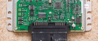
- Engine control unit;
- Electronic ignition coil;
- Spark plugs;
- Idle speed sensor;
- Crankshaft sensor;
- Air damper sensor;
- Tachometer;
- Fan motor cooling the radiator;
- Electronic fan motor control relay;
- An indicator that monitors engine performance;
- Diagnostic connector.
Wiring diagram UAZ Bukhanka
If any failure of electronic equipment occurs, the current in the node that is responsible for this device will increase, resulting in a short circuit.
The wire through which the current passes to the fuse burns out and melts, as a result of which the circuit breaks and the device turns off, but its integrity is maintained.
That is, thanks to fuses, the main parts are protected from overheating in the event of a short circuit.
How to properly remove and install the mounting block?
If the electrical circuit is made with high quality, it will greatly facilitate the process of installing and removing electronic equipment. So, the algorithm for removing the mounting block:
- Disconnect the wiring from the negative terminal of the battery;
- Open the hood and remove the cover from the fuse and relay box. To do this, you need to press out 4 plastic latches;
- Move the rubber cover;
- Disconnect the upper block of the wiring harness from the block;
- We unscrew the 2 nuts that secure the block;
- We take out the block from the compartment, which is located in front of the windshield;
- We disconnect the lower blocks of the wiring harnesses from the block;
- Install fuses and relays in reverse order.
Repairing the mounting block involves replacing printed circuit boards. So, the algorithm for repairing the mounting block:
- Remove the mounting block;
- Remove the 8 screws that secure the bottom cover;
- Using a screwdriver, open the bottom cover;
- We check the condition of the tracks along which the current passes and the quality of soldering. If defects are detected, they must be eliminated, but if this is not possible, then completely replace the unit;
- Install the mounting block in reverse order.
Did you find this article useful?
:
Source: https://autodont.ru/jelektro/elektrosxema-na-avtomobil-uaz-buxanka