Connection diagram for generator in VAZ cars
The generator in cars is designed to generate electricity and charge the battery. If the normal operation of a car electric generator is disrupted, the battery begins to discharge and soon the car will stop starting completely - there is not enough battery charge. This device consists of a three-phase diode bridge, which, in turn, has 6 silicon diodes. Electrical voltage is created by the excitation of the rectifier at the moment when the rotor poles change under the stator windings. When the rotor rotates inside the machine stator, the poles of the rotor change. To increase the value of magnetic fluxes, the stator contains an electromagnetic exciting winding in the area of the magnetic cores. Marking and designation of wires:
- P - pink.
- F - purple.
- O - orange.
- B&W - black and white.
- KB - brown and white.
- CHG - black and blue.
- K - brown.
- H - black.
- B - white.
Answers (1)
there may be an inter-turn short circuit in the stator winding; at the same time, you need to check the integrity of the diode and the resistance on the instrument panel; the resistance could “burn out” when the voltage surges
I went through the generator, the generator was still warming up immediately and very strongly, I changed the winding, checked the diode bridge and installed an additional diode, installed it and it works very well, with all the electronics turned on, the voltage is no less than 13.5.
I went through the generator, the generator was still warming up immediately and very strongly, I changed the winding, checked the diode bridge and installed an additional diode, installed it and it works very well, with all the electronics turned on, the voltage is no less than 13.5.
does that mean the problem is solved?
I discovered that the problem was solved, but another one appeared, when the engine is running, the battery light glows, but this is only at 800-900 rpm, you rev up the gas to 1000, everything is fine, and even when the voltage is smoldering 13-14, but if you turn on something at idle consumer, the volts start to drop to 11, but I’ve already driven more than 100 km, and the battery won’t sit down, I’m already confused about what the problem could be.
Everything needs to be checked, the same spark plugs, coils, armor wires. Well, all the contacts
The main source of power in a car is a generator; it is like a “mini-power station”. Incorrect or unstable operation of this unit can result in poor battery charging. A failed generator does not provide charging, therefore, the on-board network of the car will work on a battery that will not last long. As a result, the battery is completely discharged, the engine “stalls” somewhere outside the city, and you have a new “headache” and the need to replace the generator.
In order to prevent such a scenario, it is necessary to regularly monitor the condition of this device, as well as the charging it provides. If you notice any interruptions in operation, you need to check the generator, and you will now learn how to do this.
But before that, I think it is necessary to talk about precautions and certain rules that must be followed when checking this electrical appliance in order not to damage it.
. It is forbidden:
- Check the functionality of the generator by short circuiting, that is, “to spark.”
- Connect terminal “30” (in some cases “B+”) with “ground” or terminal 67 (in some cases “D+”).
- Allow the generator to operate without consumers turned on; operation with the battery disconnected is especially undesirable.
- Perform welding work on a car body with the generator and battery wires connected.
- . Important:
- The test is carried out using a voltmeter or ammeter.
- The valves are checked with a voltage not exceeding 12 V.
- When replacing the wiring of an electric generator, it is necessary to select wires of a similar cross-section and length.
- Before checking the device, make sure that all connections are working and that the drive belt is properly tensioned. A belt is considered to be correctly tensioned if, when pressed in the middle with a force of 10 kg/s, it bends no more than 10-15 mm.
Connection diagram for the VAZ-2101 generator
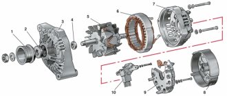
Structurally, generator 2101 consists of the following main elements:
- The rotor is a moving part that rotates from the engine crankshaft. Has an excitation winding.
- The stator is the stationary part of the generator and also has a winding.
- Front and rear covers , inside of which bearings are installed. They have eyelets for attaching to the internal combustion engine. The back cover contains a capacitor necessary to cut off the alternating current component.
- Semiconductor bridge - called a “horseshoe” for its similarity. Three pairs of semiconductor power diodes are mounted on a horseshoe-shaped base.
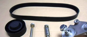
- A pulley on which the VAZ-2101 generator belt is placed. The belt is V-shaped (on modern cars a multi-ribbed belt is used).
- The voltage regulator is installed in the engine compartment, away from the generator. But still it must be considered part of the structure.
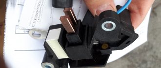
- The brushes are mounted inside the generator and transmit the supply voltage to the field winding (on the rotor).
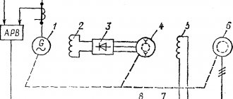
Connection diagram for the VAZ-2107 generator
1 - battery; 2 - negative diode; 3 - additional diode; 4 - generator; 5 - positive diode; 6 - stator winding; 7 - voltage regulator; 8 — rotor winding; 9 — capacitor for suppressing radio interference; 10 — mounting block; 11 — battery charge indicator lamp in the instrument cluster; 12 - voltmeter; 13 — ignition relay; 14 - ignition switch.
Connection diagram for the VAZ-2108 generator
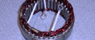
The VAZ-2108 generator has a rather massive stator winding, since it uses a large cross-section wire. It is with its help that electricity is generated. The wire is wound evenly over the entire inner surface of the stator into recesses specially provided for this purpose in the magnetic core. It’s worth talking about the latter separately. The middle part, the generator stator, consists of a series of thin metal plates pressed tightly together. They are often boiled on the outside to prevent separation.
Connection diagram for the VAZ-2109 generator
- Alternator. The 37.3701 or 94.3701 series can be installed.
- Negative diode.
- Additional diode.
- Positive diode.
- Alternator warning lamp, also known as battery discharge lamp.
- Instrument cluster.
- Voltmeter.
- Relay and fuse box located in the engine compartment in the compartment between the engine and the vehicle interior.
- Additional resistors built into the fuse mounting block.
- Ignition relay.
- Egnition lock.
- Accumulator battery.
- Capacitor.
- Rotor winding.
- The voltage relay is located in the engine compartment.
Connection diagram for the VAZ-2110 generator
On VAZ-2110, 2111 and 2112 cars, a 94.3701 generator was installed with a maximum output current of 80 Amperes and a voltage = 13.2–14.7 Volts.
Here is a breakdown of the connection diagram for the generator on the ten :
- Battery 12V;
- generator 94.3701;
- mounting block;
- egnition lock;
- battery charge indicator lamp in the instrument cluster
How to check the generator yourself
How to check a VAZ generator using the example of model 2109. Generator type 94.3701 alternating current, three-phase, with a built-in rectifier unit and an electronic voltage regulator, right-hand rotation.
Generator connection diagram . The voltage to excite the generator when the ignition is turned on is supplied to terminal “D+” of the regulator (terminal “D” of the generator) through indicator lamp 4 located in the instrument cluster. After starting the engine, the excitation winding is powered by three additional diodes installed on the generator rectifier block. The operation of the generator is controlled by a warning lamp in the instrument cluster. When the ignition is turned on, the lamp should be on, and after starting the engine, it should go out if the generator is working. If the lamp is brightly lit or glows half-lit, it indicates a malfunction.
The “minus” of the battery should always be connected to ground, and the “plus” should always be connected to the “B+” terminal of the generator. Failure to turn the battery back on will immediately cause increased current through the generator valves and damage them.
It is not allowed to operate the generator with the battery disconnected. This will cause short-term overvoltages to occur at the “B+” terminal of the generator, which can damage the generator voltage regulator and electronic devices in the vehicle’s on-board network.
Checking the voltage regulator
- In order to check the voltage regulator, you will need a voltmeter with a scale from 0 to 15 V. Before starting the test, you should warm up the engine for 15 minutes at medium speed with the headlights on.
- Measure the voltage between the generator ground terminals and “30” (“B+”). The voltmeter should show normal voltage for a particular vehicle. For example, for a VAZ 2108 it will correspond to 13.5–14.6 V. If the voltage is lower or higher, the regulator most likely requires replacement.
- In addition, you can check the regulated voltage by connecting a voltmeter to the battery terminals. It should be noted that the result of such a measurement will not be accurate if you are sure that the wiring is 100% intact. In this case, the engine should operate at medium speeds with the headlights and other consumers of electricity turned on. The voltage size must match a certain value for a specific car model.
Replacement and removal of the electric generator
The generator on a VAZ car is removed either for complete replacement in case of failure or to carry out repair work to replace faulty parts. To perform dismantling, prepare a standard set of tools; it is advisable to drive the car into the inspection hole.
- Disconnect the battery.
- Remove the protective rubber cap from terminal “30” and unscrew the nut and remove it from the wire stud.
- Disconnect the block with wires from the generator connector.
- We loosen the tightening of the generator to the adjusting bar, then lift it all the way up to the cylinder block and remove the belt from the pulleys.
- Completely unscrew the bolt securing the adjusting bar to the cylinder block, then from the bottom of the car unscrew the 2 bolts securing the lower bracket to the block and remove the generator, pulling it out of the engine compartment.
Generator VAZ 2110
The generator set is a fairly reliable device that can withstand both increased vibration of the power unit and large differences in engine compartment temperatures, and also has high resistance to the effects of a damp environment and dirt. The generator output current parameters must be stable in all engine operating modes, at any its loads and rotational speeds. The main requirements facing the generator are:
- The parameters of the generated electric current must be such that, under any engine operating modes and load on the vehicle’s on-board network, not only does the battery not intensively discharge, but it is also recharged;
- At any engine speed and load changes throughout the entire range of its operation, the voltage in the vehicle's electrical circuit must be stable and correspond to the declared value.
Attention! These requirements are due to the fact that the car battery is very sensitive to voltage changes in the on-board network. Its insufficiency causes the battery to be undercharged, which can lead to subsequent difficulty starting the engine. An excess leads to overcharging, which in turn is fraught with accelerated failure of the battery.
Checking the return current
- To measure the recoil current, you need to cover the wire that goes to terminal “30” (“B+”) with a probe.
- Then, start the engine and take a measurement; during the measurement, the engine should be running at high speeds. Turn on electrical appliances one at a time and take measurements for each consumer separately.
- Then calculate the readings.
- The following test must be carried out with all energy consumers switched on at the same time. The measurement value should not be lower than the sum of the readings of each consumer, when you measured each of them in turn, a discrepancy of 5 A downward is allowed.
Device
Before you look for alternator faults in your VAZ 2110, you need to know that the fundamental design and principle of its operation are the same for all types of cars. They can differ only in dimensions, workmanship and location of mounting fasteners. Therefore, to broaden your horizons, you can listen to the advice of owners of all brands of cars, since some generator spare parts are interchangeable.
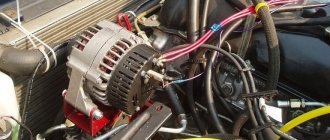
The photo highlights the main components of the generator:
- Alternator belt pulley (I hope there is no need to explain its purpose);
- A housing consisting of a front half located on the pulley side and a rear half, which is installed on the slip ring side. In addition, in the rear part of the case there is a brush assembly, a rectifier, a voltage regulator, as well as electrical wiring leads for connecting to the vehicle's electrical circuit.
The stator is installed in the housing, and the rotor support bearings are placed; it also has fastenings for installing the generator on the car engine.
- A rotor with excitation windings, the terminals of which are connected to cylindrical slip rings made of copper;
- The heart of the generator is the stator. It is in the grooves between its steel sheets where the three-phase winding is located and the electric current necessary for the car is generated;
- Assembly of rectifier diodes (no comments);
- A voltage regulator is necessary to maintain the voltage in the vehicle's electrical circuit within the specified parameters during changes in loads, generator speed and ambient temperature;
- Brush assembly, where there are spring-loaded brushes in contact with the rotor slip rings;
- Plastic cover protecting the diode module.
Excitation check
The main symptoms that prove the inoperability of the CB on the generator are indicators of external characteristics. In other words, if voltage does not flow through the terminals of the generator, then the unit should self-excite according to the principle. If this does not happen, there is a problem.
The operation of the generator on diesel units is clearly visible. They receive a smaller dose of fuel than usual as soon as the generator develops a small amount of power. Thus, the diesel installation remains underutilized.
It is clear that when the fuel supply to the cylinders is reduced, the speed will also decrease. Using it (speed), it will be possible to determine the decrease in the voltage of the generator, and therefore its excitation.
If the voltage product in the generator increases, then the magnetic saturation of the CB should not increase, otherwise the insulation strength of the electric machine will not withstand. The generator current can also be called limited in some values, which, if increased, will lead to burnout of the armature winding.
Source
Principle of operation
Let's move on to the most interesting part of our article. So, turn the ignition key in the lock and:
- Electric current is supplied to the slip rings, through the brush assembly, and then to the rotor field winding;
- In the winding of the rotor, which begins to rotate simultaneously with the engine crankshaft, there is a magnetic field that penetrates the stator windings, resulting in a variable voltage at its terminals;
- When the generator reaches a certain rotation speed, it goes into self-excitation mode, that is, the current to the rotor field winding begins to flow directly from the generator itself;
- The generated alternating voltage is converted into direct voltage using a rectifier unit. It is in this state that the processes of charging the battery and providing electricity to current consumers take place;
- The voltage regulator comes into operation while the vehicle is moving, when the load on the generator and its rotation speed change. Its task is to regulate the switching time of the exciting rotor winding.
Lada 2108 Charoit › Logbook › Exciting the generator
Yesterday I argued with one person on “Drive” whether it is possible to connect the excitation winding directly to the battery.
The man claimed that this is how it is always connected, just through the ignition switch. And what in general is through a diode or what, it doesn’t matter, “not to 220.” Alas, people often make claims without going into details of the device. Therefore, I’ll tell you how the generator excitation works on the VAZ-2108 and similar ones. I won’t fully describe how this works, but I’ll just tell you what’s possible, what’s not, and why. I note that we are talking about the LADA Samara family, but the same applies to the 110, and with some reservations to Priora, Kalina and Granta. To answer the question briefly, is it possible to provide excitation from a battery?
, then yes, it is possible, but through a diode.
In details.
If the generator excitation suddenly disappears, then you can supply voltage from the battery to input D of the generator during or immediately after starting the engine. Soon, a working generator should switch to self-excitation mode from the voltage it generates. You need to connect through a diode, but not directly, otherwise you risk burning out the generator's additional diodes. And of course, only with the ignition on, otherwise you will drain the battery while parked.
Now in more detail.
By itself, simply by rotating the rotor, the generator will not generate voltage. In order for it to start doing this, it needs to be excited - “give a kick”, and for this it has an excitation winding that consumes some current. Voltage is supplied to it through contact D of the generator and the voltage regulator. The regulator also turns off the winding when the generated voltage is exceeded, in fact, this is its entire function. There are 2 power modes for the excitation winding. Starting, when the engine starts; and working, when the generator is already running. In the first case, power is supplied to the winding from the battery through a charge control lamp and a diode connected in series with it. In the second case, when the generator begins to generate voltage, the winding is powered through its 3 additional diodes - autonomously.
It happens that the generator does not want to be excited.
The very first and simplest possible option here is to check the terminal on contact D of the generator, there may be a bad contact there, everything is very simple: tighten it up, clean it, and be happy. Another option: the charge control lamp has burned out. Naturally, it can be replaced. But if there is no way to change it now, on the road, for example, there are the following options: - “accelerate”, and it is likely that the generator will be excited due to residual magnetization; — apply voltage to the excitation winding artificially, i.e. separate wire from the battery. Let's talk about the last method.
We take a wire, a diode in series with it and connect it from the battery positive to the D-contact of the generator. If the generator is working properly, it will go into offline mode and the wire can be disconnected. Now the main thing: why the hell does a goat need a diode? And it is needed in order not to kill additional diodes. Let's look at the diagram:
The excitation winding of the VAZ-2108 and similar cars is powered not from the main diodes, but from additional diodes specially designed for it (in the diagram - horizontally on the left). These diodes are designed for low current. If you look at the diagram, you can see that current cannot flow from them anywhere else than to the excitation winding. If we connect the “+” of the battery directly to the D-contact (aka 61), and the generator gets excited and begins to generate voltage, then the current will flow through both the 3 main diodes and 3 additional ones - in parallel. And it will flow to the entire load of the car! And the additional diodes are low-current, and they can simply burn out, which will lead to a complete loss of excitation and replacement of the diode bridge or at least these diodes.
Diagnostics
Due to the fact that the price of a new generator is “biting”, and maintainability is quite high, many motorists do it themselves with their own hands to eliminate generator malfunctions in the VAZ 2110, which I suggest you do with the help of these instructions:
Fault No. 1
In the case when the control light on the instrument panel indicates a discharge of the battery, and when checking with a tester in the electrical circuit of the car, the voltage does not rise above 13.2 volts, it is necessary to check:
- Tension of the VAZ generator drive belt - tighten if necessary;
- If the rectifier block valve is damaged, replace the entire rectifier block;
- Diodes powering the exciting winding of the rotor - replacement of diodes or the entire rectifier block;
- The outputs of the exciting winding coming from the slip rings for their unsoldering - solder the outputs/replace the rotor or the entire generator assembly.
It is also possible that the stator winding may short-circuit, break or short circuit to ground (in this case, noise from the generator appears in the VAZ 2110, the generator “howls”). These assumptions are checked using an ohmmeter; if a malfunction is detected, the stator or the entire generator must be replaced.
Malfunction No. 2
The warning lamp in the instrument panel also indicates that the battery is low, and the tester displays a voltage value in the vehicle circuit of at least 14.7 volts:
- The voltage regulator has definitely failed (the contacts of the “DF” output have closed with ground) - replace the regulator.
Malfunction No. 3
The generator noise is clearly audible in the VAZ 2110:
- If sounds such as howling and squealing are heard. When disconnected, the wires remain, and when the drive belt is removed, they disappear, this means that the bearings have failed - replace the bearings (the front one is replaced as an assembly with a cover);
- If, when the wires are disconnected, the noise disappears, this indicates a short circuit in the stator windings and their connection to ground—replace the stator/generator.
Also in this case, one of the valves may close, which threatens to replace the rectifier unit.
Malfunction No. 4
The warning lights in the instrument panel do not light up when turning the ignition key:
- Checking the “F19” fuse in the mounting block - replacement (it is advisable to find out the reason for the fuse failure);
- Open circuit in the instrument cluster “ignition switch” - check the integrity of the blue wire with a red stripe running from the mounting block to the ignition switch, as well as the orange wire running from the instrument panel to the mounting block;
- Malfunction of the ignition switch contact group - check the presence of a contact with a tester, if necessary, replace the contact group or the entire ignition switch.
Checking the generator diode bridge
- Turn the voltmeter into AC measurement mode and connect it to ground and terminal “30” (“B+”). The voltage should be no more than 0.5 V, otherwise there is a possibility of diode failure.
- To check the breakdown for ground, you need to disconnect the battery and also remove the generator wire that goes to terminal “30” (“B+”).
- Then connect the device between terminal “30” (“B+”) and the disconnected generator wire. If the discharge current on the device exceeds -0.5 mA, it can be assumed that there is a breakdown of the diodes or the insulation of the generator diode windings.
- The strength of the recoil current is checked using a special probe, which is an addition to the multimeter. It is something like a clamp or pliers that grips the wires, thus measuring the strength of the current that passes through the wire.
Malfunction No. 5
When the ignition is turned on and the engine is running, the warning lamp indicating a low battery does not light up, the remaining lamps in the instrument cluster work:
- Burnt-out control lamp/poor contact – replace the burnt-out lamp/clean and press the contacts in the seat;
- Open circuit “generator output “D” to the instrument panel” - check for continuity of the brown wire with a white stripe coming from terminal “D” to the instrument panel;
- Oxidation of contact rings, as well as hanging and wear of brushes - the brush holder assembly with brushes should be replaced, the contact rings should be wiped with a clean cloth moistened with a degreaser;
- Open circuit “DF terminal – ground” (damage to voltage regulator) – replace the regulator;
- Broken brush holder wire from terminal “D+” - restore contact;
- The positive diodes (valves) have closed - replace the rectifier unit;
- The leads coming from the slip rings to the rotor excitation winding have been unsoldered - solder the leads in place/replace the rotor/replace the generator.
This is where the list of the main malfunctions of the VAZ 2110 generator ends, I hope that this instruction will help you out at the right moment. As they say - no nail, no wand)))
Checking the generator excitation current
- To check the generator excitation current, start the engine and give it high speed.
- Place the measuring probe around the wire connected to terminal 67 (“D+”), the readings on the device will correspond to the value of the excitation current; on a working electric generator it will be 3-7 A.
To check the field windings you will need to remove the brush holder and voltage regulator. It may be necessary to clean the slip rings, and also check for breaks in the windings or short circuits to ground.
- For this test, an ohmmeter is used, its probes must be applied to the slip rings, the resistance value should be in the range of 5-10 Ohms.
- Then connect one ohmmeter probe to any slip ring, the second probe to the stator. On a working generator, the multimeter will show an infinitely high resistance, otherwise the field winding will short to ground.