General information
With the growth of scientific progress and the production of electric current, which is one of the main types of energy, human life has become much more comfortable. After all, thanks to him, or rather, his work, various mechanisms are set in motion, rooms are illuminated and heated, and so on.
The current in a conductor appears due to electromotive force (EMF), which causes particles carrying a charge in the conductor to move. If a conductor is exposed to a magnetic field, then this phenomenon is called electromagnetic induction.
In other words, if the following condition is met: a conductor moves in a magnetic field or an electromagnetic field moves around the conductor, then an electric current appears in the latter. As a result of this phenomenon, transformers, electric motors and generators were created.
In modern generators, this circuit contains at least three windings necessary to create a larger EMF. To clearly understand the purpose and processes occurring during the conversion of electricity, you need to familiarize yourself with the design and operating principle of the generator (EG).
How does an electric generator work?
The main part of the device is the body, which consists of two covers and is made of aluminum alloy, which ensures effective removal of excess heat. The body is provided with a mounting flange or boss with a through hole for a long bolt (depending on the make of the car). In general, the unit structure looks like this:
The design of the electric current generator has changed little since its invention. This unit, designed to convert rotational energy into electricity, is distinguished by its perfect design and high efficiency. The efficiency of the device is 98–99%!
Since current-carrying sliding contacts (brushes) are the weak link of the structure and quickly wear out, more modern generators implement a brushless method of current transmission. The process involves a sprocket mounted on the shaft and an additional winding attached from the inside to the end of the back cover.
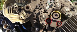
Despite the apparent complexity of the design of a car electric generator, disassembling it is quite simple. To remove the rotor, simply unscrew the casing and the screws holding the 2 covers together, after first removing the drive pulley.
Generator device
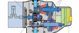
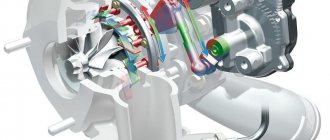
Almost all of them are similar in their design, but there are some differences - this is the method of setting the mechanical part in motion (Figure 1).
It consists of main components:
- frame;
- stator;
- rotor, or armature;
- switching box.
Figure 1. Generator cross-section
The housing, which acts as a frame, serves to fasten all the main parts. In addition, it contains bearings necessary for smooth rotation of the shaft and increasing the service life of the device. The body is made of durable metal, and it also serves to protect the internal parts of the machine from external damage.
The stator has magnetic poles, presented in the form of a fixed winding to excite magnetic flux F. It is made of special steel, which is called ferromagnetic. The rotor is a moving part, and it is driven by some force. As a result, a potential difference or voltage (U) is formed at the armature (rotor). The switching unit (box) is necessary to remove electricity from the rotor. It consists of conductive rings connected to graphite current collector contacts.
Design of a car generator: design features
Generators in cars may differ in size and implementation schemes of certain devices (generator housing, drive, etc.). Also under the hood, the solution may have different installation locations. The following elements are common in the device:
These components are located in the housing. The key parameters of generators for cars are the following nominal indicators: voltage, current, rotation speed, self-excitation at a certain frequency, device efficiency.
The rated voltage can range from 12 to 24 V, which depends on the design of the vehicle’s electrical system. The rated current is the maximum current that the device delivers at a rated speed of 6 thousand rpm. These features represent the so-called current-speed characteristic. In parallel with the nominal indicators, when choosing, you should consider:
Now about the device itself. The body is a pair of covers that are held together with bolts. The most common cover material is aluminum alloy, which is non-magnetic, provides low weight and good thermal energy dissipation (heat dissipation). The housing additionally has separate slots for ventilation, and also has a fastening element for installing and fixing the generator.
Another function of the voltage regulator is to change the voltage, which is necessary to effectively recharge the battery, taking into account the outside temperature. As the outside temperature drops, the device supplies more voltage to the battery.
As for the generator drive, this solution is a belt drive (using V-belts or poly-V-belts) through which the rotor rotates. The generator rotor rotates up to 3 times faster than the crankshaft itself. Let us add that modern cars use a poly-V belt.
It should also be noted that some car models may have an inductor-type generator installed. An inductor generator means that there are no brushes in its device; the winding is installed in the stator. The rotor of such a generator without brushes is made of thin iron plates. The material for making plates is transformer iron. The inductor generator operates on the principle that a change in magnetic conductivity occurs in the air gap that is present between the stator and the rotor.
Operating principle
The law of electromagnetic induction is the basic principle of operation of an alternating current generator. The device and principle of operation are almost the same for all types. Induction occurs, as a result of which an EMF appears in the circuit when rotating in a uniform magnetic field. This magnetic field rotates.
The alternator works as follows:
- the rotor is a magnet that, when rotating, transmits a magnetic field to the stator windings;
- the stator is a coil to which wires are connected to collect electrical energy;
- when U appears, it is removed.
The rings are made of copper conductor and rotate with the rotor and shaft simultaneously. Brushes serve to transfer current from the shaft to the rings. There are a lot of varieties and, therefore, they can be classified according to the following criteria:
- constructive plan;
- excitation method;
- number of phases: single-phase, two-phase and three-phase;
- connection type of stator windings.
According to the design plan, they come with fixed poles and an armature (it rotates) and, conversely, with rotating magnetic poles (the armature remains stationary). The latter type has become widespread due to the production of higher current. When the rotor rotates, the pole pieces of which have a minimum gap between the stator to create maximum F, an emf is generated in the turns of the stator coil. The tips are selected in such a shape that U is close to sinusoidal.
According to the method of excitation they are also divided into subtypes.
- The windings are powered by direct current (independent excitation). This model is powered by another generator.
- It is powered by its own rectified current (with self-excitation).
- Excitation from permanent magnets.
The most commonly used connection is a star and a neutral wire, which acts as a phase imbalance compensator. In addition, the neutral wire allows you to eliminate the DC component in the event of harmful ring currents (hereinafter referred to as I), which reduce power and affect heating.
An active load with a neutral wire is connected to the generator, the windings of which are connected like a star. In addition, there is a triangle connection, which is rarely used.
With this connection of the windings, low power devices can be connected. Generators differ from each other in technical parameters.
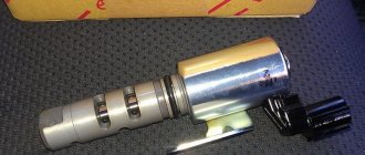
Why is there a voltage regulator in the generator?
When the speed of the crankshaft and, accordingly, the rotor changes, voltage surges may occur in the on-board network, which negatively affect the work of consumers. Surges are eliminated by limiting the excitation current transmitted through the brushes from the voltage regulator to the rotor. Control is carried out by changing the connection time of the armature winding depending on the load on the on-board network.
If the regulator malfunctions or the brush assembly and slip rings are damaged, the battery may be undercharged or overcharged. Long-term operation of a machine with such a defect will lead to battery failure.
A generator malfunction can be determined by the indicator on the instrument panel. When the battery charge light comes on after starting, it indicates that the voltage in the network is insufficient, while blinking indicates that it is too high.
We recommend: Car suspension: elements, diagram, types
Technical specifications
Generators also differ in basic quantities, which are technical parameters. Among the total number, the most significant can be identified:
- electrical U;
- produced I;
- power (hereinafter P);
- rotation speed (revolutions per minute);
- coefficient P - cos f.
U is regulated due to a change in Ф when U regulators (variable resistor or electronic U regulator) are connected in series to the excitation winding circuit. If there is an exciter generator, the current is directly regulated on it. When using alternating U generators from permanent magnets, U stabilizers or regulators should be used.
When connected to a circuit, a parallel connection of EG is used, one of which is considered a backup. To connect the backup EG to the conductor buses, it is necessary to fulfill the condition of equality of the EMF and U on these buses. Also the phase shift must be zero. This process is called EG synchronization. To synchronize the generator with the network, a synchroscope is used, which is an ordinary incandescent lamp and a voltmeter (zero).
The more often they blink, the faster the synchronization process and adjustment are approaching the final stage. You need to pay attention to the voltmeter, which should show a value of 0 with a synchronized EG.
What are the requirements for a car generator?
There are a number of requirements for a car generator set:
At the same time, every car owner should pay special attention to the level and stability of the output voltage. This requirement is due to the fact that the battery is sensitive to such changes.
For example, if the voltage drops below normal, the battery is not charged to the required level. As a result, problems may occur during the process of starting the engine.
In the opposite situation, when the installation produces increased voltage, the battery is overcharged and breaks down faster.
Source
The main purpose
Generators are widely used to produce electricity and are huge machines that produce high power current. However, not all varieties have such dimensions. Devices used in vehicles are used as sources of U. This is very convenient, since the chassis of the vehicle performs mechanical movements and it would be foolish not to use this type of energy to rotate the EG.
Three-phase alternating current generators are used together with a bridge rectifier and are used to charge the battery. In addition, they are used to power electrical consumers, for example, the ignition system, light signaling and lighting, on-board computer, and so on. The device is connected to the U regulator, thanks to which the value of U remains constant. AC devices are used in cars, since they are smaller in size compared to their counterparts - constant U EG.
Types of regulators
Different generators use different types of relay regulators. These are two-level devices, electronic devices, three-level, multi-level.
The first two-level relays are now considered obsolete. But car enthusiasts, despite this, continue to actively use them in car generator connection diagrams. This two-level regulator is based on an electric magnet connected to a sensor on the winding. The setting element is springs – there are several of them. The movable lever acts as a comparing component - it also switches the wiring. The main disadvantage of regulators of this type is their small resource.
Electronic models of regulators with a maximum current of a car generator of up to 40 A are semiconductor. They have a great resource. As for their malfunctions, compared to their two-level analogues, breakdowns are less common here.
Three-level solutions are practically no different from the regulators discussed above. The only difference here is that these devices also have additional resistance.
Multi-level solutions are another type of relay regulators. They have three or even five resistances. In addition, models with tracking mode are available for sale.
Types of devices
Despite the same structure, they are used in various types of devices and types of transport. A certain type of EG is used in various situations. There are main types of generator devices, which are classified by type of application:
- automobile;
- electric;
- inventory;
- diesel;
- synchronous;
- asynchronous;
- electrochemical.
The main purpose of a car battery is to rotate the crankshaft. A new type is used - a hybrid generator that acts as a starter. The basic principle of operation can be considered to be used to turn on the ignition, with I flowing through the slip rings and then to the alkaline part. Next, it moves to the excitation winding, a magnetic field is formed and the rotor is started, creating electromagnetic waves.
These waves penetrate the stator winding. Afterwards, an alternating current appears at the output of the winding. If the generator operates in self-excitation mode, then the rotation speed increases to the permissible value, and the alternating current is converted into direct current using a rectifier.
The inverter type of EG is very common. It is a self-contained power source that produces high-quality electrical energy. It is used almost everywhere and is a very reliable power source, in which there are no surges in U. Basic principle of operation:
- high-quality alternating current is generated, which is rectified using a diode bridge;
- direct current accumulates in batteries;
- The batteries are converted into stabilized alternating current using an inverter.
Another excellent and durable option is a diesel EG, which converts fuel energy into electrical energy. Fuel is burned and converted from chemical energy to thermal energy. The thermal energy is then converted into mechanical energy. Then a transformation occurs according to the old scheme: mechanical energy into electrical energy.
In a synchronous EG, the rotor acts as a permanent magnet with poles, the number of which ranges from 2 or more. However, a factor of 2 must be observed. During startup, the rotor generates a weak electromagnetic field, but as the rotation speed increases, a current appears in the field winding. During this process, U appears and is supplied to a device that controls its value when the electromagnetic field changes. Synchronous-type generators have proven themselves to be excellent thanks to the stably produced U. However, they have a significant drawback - a possible overcurrent, as well as the presence of a brush assembly, which sometimes has to be serviced.
The principle of operation of an asynchronous type EG is based on constant being in the “braking with a moving part” mode, rotating in advance. The rotor can be either phase or squirrel-cage. An auxiliary magnetic field is created by the field winding and continues to be induced in the rotor. The frequency of the current and U depend on the number of revolutions.
A very interesting source of electricity is the electrochemical generator. Electrical energy is obtained from hydrogen. It is a chemical source of current, as a reaction of this type of interaction between oxygen and hydrogen molecules takes place.
In addition, when using EG, it is necessary to use devices in conjunction with them that regulate the parameters U and frequency. The principle of operation of the device is to maintain constant values of U and other parameters of electricity for high-quality power supply to consumers. The regulator also protects the generator from overloads and emergency mode. If an emergency occurs with a regulator, the generator will not start and will remain off. This is possible in case of a short circuit in the consumer circuit. These devices pick up U, frequency and I, as well as F.
How does he work
First, let's figure out how this device functions. His work scheme is as follows:
- The key is inserted into the ignition switch;
- The current goes to the excitation wires;
- The magnetic field created by the armature passes through the stator windings, and voltage appears at its terminals;
- When the armature rotation frequency becomes high enough, the self-excitation mode begins;
- The rectifier unit provided by the car design converts alternating current into direct current;
- The voltage regulator starts working when the crankshaft rotation speed changes, and the time for which the excitation wire is activated is adjusted.
The presented video will allow you to clearly get acquainted with the principle of operation of the generator.
Beginners are very interested in the most important question, without which there is no point in trying to fix something on their own - what is the generator used for.
First of all, the generator’s task is to provide energy to all electrically dependent equipment.
The mistake many people make is that the equipment is powered by a battery. The battery is needed to maintain the functionality of the devices when the engine is turned off. It powers the audio system, alarm system, etc.
When the engine is started with the help of the battery, all the reins of power pass to the generator. He is now responsible for the operation of the audio system, air conditioning, power windows, etc.
The second, but no less important task of the battery is to recharge the battery. This happens when the engine is running. If it were not for the generator, the battery would not be able to provide power to all consumers for a long time; it would have to be charged regularly in the garage.
Main parts of alternator
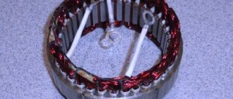
The design of the product includes two main parts: stator (stationary element), rotor (rotating part). The stator, which is a hollow cylinder, contains a magnetic system consisting of steel sheets mounted in a package. Inside them there are grooves insulated with a dielectric (usually fluoroplastic film is used), in which windings of copper wire are located. Each coil represents one phase (there are 3 in total), in which the turns are connected in series or parallel. The part of the coil that protrudes from the grooves is called the end joint. For each of the three windings, one terminal is connected to a common point, which is not “operated” and is carefully isolated from the housing and other parts (this connection is called a “star”). The resulting tension is removed from the other three ends.
The rotor is a massive core with an excitation winding, made of steel. The shaft can be positioned horizontally, which is typical for most structures, or vertically, as this installation method is practiced on hydraulic turbines. A running generator can be cooled with air, water, oil and even hydrogen.
Details about the operating algorithm
The principle of operation of the generator is based on a simple physical phenomenon called electromagnetic induction. The point is this: if you apply a magnetic field to a multi-turn winding of copper wire that changes direction at a certain frequency, then an alternating current of the same frequency will appear at the output of the coil. All that remains is to create the mentioned field around the stator windings that generate voltage.
In practice, electricity generation occurs according to the following algorithm:
We recommend: The principle of operation of a variator: what types are there, pros and cons
The voltage regulator relay can be part of the generator set or used as a separate unit.
The current in the stator windings arises as a result of the rotation of the alternating magnetic field created by the rotor coil. The faster the shaft rotates, the higher the voltage and frequency at the output. Conversion to direct current is provided by semiconductors (diodes) mounted on a heat sink plate and blown by a fan impeller.
The brushless generator design allows the stator winding to be excited without an external power source. The magnetization of steel bushings begins at low shaft speeds due to the special rotor design and additional coil. Therefore, when you push start a car with a discharged battery, the crankshaft revolutions are enough for the electric generator to start working.
Principle of operation
The operation of the generator is based on electromagnetic induction. To obtain alternating voltage, you need a coil in which direct current is present. This will cause a magnetic field to form in the exciting winding. A steel pole system is also needed to supply the magnetic field to the coils, called the stator winding. As the rotor rotates, the “south” pole and then the “north” pole appear alternately opposite the stator coils. How does this happen in practice?
The stator winding, which is the power winding, is in a stationary state. The rotor is driven mechanically: this can be the energy of water flow, wind, or a chain or belt drive that transmits rotational energy from, for example, a car engine. In order for the generator to start working, voltage must be applied to its excitation winding. As a result, an electromagnetic field is created, which, through the rotating rotor, induces voltage in the stator coils. As the voltage on the exciting winding increases, the voltage on the coils of the stator winding increases, and vice versa. Voltage can also be supplied to the exciting coil from the generator itself. In such a case, the generator is considered to be self-exciting.
What are SV and ARV
The gene excitation system is a complex of various devices, including: exciter, ARV, SGP, UBPV, de-excitation device, as well as additional test meters.
Excitation system
ARV is nothing more than a regulator that functions completely automatically. SGP is a means that dampens the magnetic field. UBVV is a device through which excitation is quickly boosted.
The exciter itself is the power source (PS) of the winding with constant voltage. In this case, the IP can be the gene itself, together with semiconductors and a rectifier unit (diode bridge).
ARVs are used in a synchronous gene. Here they perform the function of increasing the physical stability of the generating device. It is customary to classify ARVs into devices with proportional pitch and strong pitch. Some are capable of changing current energy due to a discrepancy in the stator voltage, while others react in a broader sense of the word.
When the current decreases, for example during a short circuit, a boost is provided. It implies a rapid increase in excitation, which affects the stop of voltage drops and maintains stability.
Correction and acceleration significantly increase the reliability of the relay.
When the generator shuts down, which can also be caused by internal short circuits, the unit should be energized. To do this, it is enough to extinguish the magnetic field, which will make it possible to reduce the size of damage to the stator winding.
To extinguish the magnetic field means to quickly reduce the magnetic flux of the gene excitation to a value close to 0. At the same time, the emf of the unit decreases.
Article on the topic: Signs of a faulty ignition coil
How to extinguish a magnetic field
Magnetic field suppression is carried out using AGP - special automatic devices operating from a relay. They are the ones who help activate resistance.
In generating devices operating on the principle of thyristor excitation, the magnetic field is reduced by switching the main valves into an inverter mode. Thus, the energy saved in the winding will be transferred to the exciter or diode bridge.
It is characterized by a CB rated voltage (NT), but it can be different.
- 100 or 600 V, if we are talking about excitation at the winding terminals.
- 100 or 8000 A, if we are talking about LT located directly in the winding, and corresponds to normal, standard operation of the generator.
You should know that the LT of the exciter should be a fraction of a percent of the LT of the generator. As a rule, values of 0.2-0.6 percent of the nominal power of the gene are considered.
As for the speed of the exciter, it depends on the rate of increase in current strength on the inductor (rotor) winding.
The excitation system (excitation system) must be calculated depending on the operation of the automatic breaker. In other words, work without ARV is allowed, but only for the time needed for repair or replacement. In other cases, the use of ARV is mandatory.
Note. If the IV still operates without ARV, then it is necessary to provide an additional protection system. These are RDUs and other means that can provide deexcitation and auto-quenching of the generator field.
The SV is obliged to provide current in a continuous mode, exceeding the LT of the generator by at least 10 percent.
Non-contact excitation system
SV can also be semiconductor. In this case, it must have an internal storage mode (internal storage mode).
It is important that protective devices that ensure stability during overvoltages are multi-functional.
| Excitation system composition | What does the excitation system provide? |
| rectifier transformer | initial excitement |
| series booster transformer | idling |
| thyristor converter (TV 8-2000/) 050-1U4) | connection to the network using the method of precise synchronization in normal modes and self-synchronization in emergency modes |
| converter cooling system | operation of the main generator in the power system with loads from no-load to nominal and overloads |
| initial excitation unit (AN V-2) | underexcitation within the limits of stable generator operation |
| automatic excitation regulator (AU1G type ARV-SD) | excitation boost by current and voltage |
| field blanking panel | effective field damping |
| relay panels | deexcitation during normal unit stops |
Operating principle of the relay regulator
If you connect a winding without a relay regulator to a source of electricity, the DC level will be high. Using a relay in the circuit, this parameter is equalized so that the electrical equipment in the car does not fail. In fact, the relay regulator of a car generator is something like a switch. If the voltage rises to 13-14 volts, the device automatically turns off the winding and turns it on when the current is lower. As a result, regular wiring connections/disconnections allow the generator to produce higher voltage.
How much such a device should produce is not important. Once the energy has already been generated, it needs to be rectified. For these purposes, the generator is equipped with a diode bridge. Since the voltages are high, the regulator comes into play, the element instantly responds to changes in current strength. This information is then sent to the comparison device. It is needed to analyze the readings and compare them with those that have just been received. If the car generator voltage is low, the regulator will increase the direct current in the circuit, thereby increasing it to the required level.
Generator repair
Generator breakdowns can be very different. In one case, for repair it is enough to replace the diode bridge, in another - to replace more significant parts.
So, among the main malfunctions is failure of the circuit. These could be breaks, short circuits, or any other violations. In this case, repairing a car generator consists of checking what current and what voltage the generator produces. Then a solution is chosen. Also, one of the breakdowns is wear of the graphite brushes or diodes in the rectifier bridge. All these faults can be easily fixed with your own hands.
Noise during operation of the generator indicates defects in the bearing units, as well as insufficient lubrication. It is also possible for the separators to wear out and the rings to turn. With howling sounds, you can notice damage such as inter-turn short circuit of the stator windings. In such cases, it is better to entrust the repair of the unit to professionals.
Charging a car battery with a generator
Charging the car battery from the generator occurs automatically when the car engine is running; the generator constantly produces current that powers your battery and all on-board systems of the car.
We hope we have clarified a little the topic of this article - how the generator works and what its operating principles are, and now you have a more complete picture in your head of what and how this most important device in a car works, as well as what output parameters and characteristics it should have.
Source