04/27/2021 3,678 Generator
Author: Ivan Baranov
The generator is rightfully considered the main component in the electrical network of a car. Thanks to the operation of this device, current is supplied to all energy consumers of the car, from optics and radio to auxiliary devices, such as a navigator and recorder. One of the main elements of this mechanism is the generator stator. You can learn more about its design, diagnostics and winding rewinding in this article.
[Hide]
Checking the generator stator of VAZ 2108, 2109, 21099 (37.3701) cars
There may be at least two malfunctions in the generator stator of VAZ 2108, 2109, 21099 cars and their modifications. This is a “break” in its windings and a short circuit of the windings to ground. A sign of a generator malfunction is the disappearance of the charging current. In this situation, after starting the engine, the battery discharge lamp on the instrument panel goes out, and the voltmeter needle tends to the red zone. If you measure the voltage at the battery terminals while the engine is running, it will be lower than that required from the generator 37.3701 13.6 V. In some cases, if there is a short circuit in the stator windings, the generator emits a characteristic howl. — A multimeter, auto tester or other similar device with an ohmmeter mode
— If there is no measuring device, a test lamp is required (a 12 V light bulb with two wires soldered)
Preparatory work
— Remove the generator from the car engine
— We disassemble the generator and remove the stator
— Clean the stator from dirt
Checking the generator stator 37.3701
Checking for a “break”
We press the multimeter probes in ohmmeter mode to the terminals of the stator winding. If there is no “break”, the device will show a resistance within 10 ohms. If there is a “break” in the stator windings, that is, no current passes through them, then the resistance tends to infinity. In this way, we check all three conclusions in turn.
checking the stator windings of generator 37.3701 for “break”
If we use a test lamp, then we apply the minus from the battery minus to one of the terminals of the stator winding (using an insulated wire), and the plus through the test lamp to the other terminal. The lamp came on - everything is normal, no - “break”. We repeat the operation one by one for all outputs.
Checking for a short circuit
We press the negative probe of the multimeter in ohmmeter mode to the stator, and the positive probe to any winding terminal. If there is no short circuit, the resistance on the device tends to infinity. We repeat the operation for each winding terminal.
checking generator stator 37.3701 for “short circuit”
When checking the generator stator for a short circuit with a test lamp, we apply a minus from the battery terminal to the stator, and a plus through the test lamp to any winding terminal. The lamp lights up - there is a short circuit, no - everything is normal. We repeat the procedure for each output.
Notes and additions
— It should be noted that similar symptoms (except for the whine of the generator) may appear if the voltage regulator, diode bridge, or generator rotor malfunction. Since a generator stator malfunction is much less common than a regulator or diode bridge malfunction, it is worth checking them first, and then proceeding to check the stator.
Five more articles on the website on electrical equipment of VAZ cars
Push-pull generator for the lazy
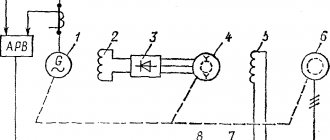
The simplest generator circuit I've ever seen:
In this circuit one can easily see the similarity with a multivibrator. I'll tell you more - this is a multivibrator. Only instead of delay circuits on a capacitor and resistor (RC circuit), inductors are used here. Resistor R1 sets the current through the transistors. In addition, without it, generation simply will not work.
Generation mechanism:
Let's say VT1 opens, collector current VT1 flows through L1. Accordingly, VT2 is closed, and the opening base current VT1 flows through L2. But since the resistance of the coils is 100...1000 times less than the resistance of resistor R1, then by the time the transistor is fully opened, the voltage across them drops to a very small value, and the transistor closes. But! Since before closing the transistor, a large collector current flowed through L1, at the moment of closing there is a voltage surge (self-induction emf), which is supplied to the base of VT2 and opens it. Everything starts over again, only with a different generator arm. And so on…
This generator has only one advantage - ease of manufacture. The rest are cons.
Since it does not have a clear timing link (oscillating circuit or RC circuit), it is very difficult to calculate the frequency of such a generator. It will depend on the properties of the transistors used, the supply voltage, temperature, etc. In general, it is better not to use this generator for serious things. However, in the microwave range it is used quite often.
How to check the generator for performance in various ways
There are two power sources in a car - a battery and a generator.
The first powers the electrical circuit when the engine is not running. The second is when the engine is already running. In this case, the battery goes into electric current consumer mode and replenishes the energy expended to start the engine. In practice, malfunctions of one or another power supply are quite common.
They often manifest themselves in the same way. The starter refuses to spin the engine, and as a result the engine does not start. When the engine is running, the warning light on the instrument panel with the battery icon lights up. It indicates that a malfunction has occurred and the battery is not charging.
Checking the generator on the car
First of all, you need to see if the alternator belt is intact. If it is not torn, then the belt tension is checked. Then it's time for the battery. Using a tester (multimeter), we measure the voltage at the terminals. It should be around 12−12.7 volts. If everything is fine, start the engine. If the battery is discharged, charge it and start the engine again.
We measure the voltage at the battery terminals. It should be within specified limits, usually from 13.2 to 14.5 volts. But on modern cars these limits may differ. If you have an instruction manual, you can read it. Deviation from the specified values in any direction is a malfunction. These deviations can be of three types:
- Lack of charging current - the generator does not work.
- There is a charging current, but below the minimum value -
- Voltage above the maximum value means the battery is overcharged.
All three cases indicate an existing malfunction in the vehicle's electrical supply system.
it is necessary to carry out a comprehensive check of the generator. But before that, conduct a visual inspection of all the wires and cables that go from the generator to the battery.
There should be no visible damage, breaks or oxidation of the electrical wiring. Be sure to check the terminals on the battery, starter and alternator. They must be clean and dry. Any oxidation, rust or dirt must be cleaned off. Often this helps restore lost contact and the car begins to work as expected. If this does not help, we proceed to a detailed check.
Step-by-step instructions for installing and assembling the tens generator
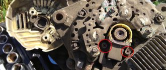
Guide to dismantling the VAZ 2110 generator:
- The tensioner nut is unscrewed.
- The generator unit moves slightly back towards the vehicle interior. The drive belt is removed from the pulleys. Then the electrical power circuits of the device are turned off. One block with wires is fixed with a nut and a stud; they must be unscrewed and disconnected. The second connector is attached using a regular block, which is detached.
- After this, the lower nut securing the assembly is unscrewed. This action is performed from under the bottom of the car. To complete the task, it is necessary to dismantle the power unit protection, if any.
- The screw that needs to be removed is usually fastened tightly. When unscrewing it, you need to treat the part with WD-40 if it is stuck and cannot be removed. You can use a hammer to remove the retainer.
- Then, from the reverse side, this element is removed completely.
- At the final stage, the nut that secures the tensioning device is completely unscrewed. The generator unit is moved to the side, this will allow it to be completely dismantled.
How to test a generator with a multimeter
The diode bridge of the generator can be checked with a multimeter, but you can also use the stand that was used to check the regulator.
But before that, first of all, without removing the rectifier bridge from the generator, connect the red wire of the tester to terminal 30 of the generator, and the black wire to the housing. Set the tester operating mode to dial (diode icon). If it is not there, then set it to 1-2 kOhm. The multimeter should show infinity. If the readings are different, the diode bridge is faulty.
Then check the current rectifiers for breakdown. Leave the positive (red) probe on terminal 30, touch the negative one to the bridge mounting bolts one by one. The multimeter display should show infinity in all cases; any others mean a breakdown.
Next, connect the positive probe to the axle mounting bolts, and the negative probe to the generator housing. In this case, the tester should also output infinity.
But in practice, such verification is most often not enough. In most cases, it is necessary to ring the generator in more detail.
Careful testing
To do this, unscrew the fastening bolts of the rectifier unit, disconnect the copper wires of the stator winding and remove the diode bridge from the generator.
Now you can test each semiconductor individually. Before checking, it is advisable to rinse the stabilizer with running water using a medium-hard brush, and then dry thoroughly. For quick drying, a hair dryer is quite suitable. Attach one of the tester probes to the diode plate, connect the second to the central terminal of each diode fixed to this plate. Then swap the probes. In one case, the multimeter should show infinity, in the other - a nominal resistance of approximately 570-590 Ohms. Rectifiers are considered faulty if:
- In the first and second measurements (when the polarity was changed), the multimeter readings are the same;
- Diode resistance is greater or less than nominal values.
Perform the same actions with the second plate of the diode bridge. If a fault is detected in one or more diodes, it will be easier to replace the entire rectifier unit. True, there are craftsmen who replace failed diodes individually, but such work requires a certain skill and dexterity.
Checking the armature and stator windings
Further inspection requires completely disassembling the generator.
First of all, visually check the anchor. Brush rings should not show any blackening, chipping or wear on the treadmills. Blackening and slight wear can be smoothed out with zero-grade emery cloth. Rings with deep grooves must be replaced or, if the thickness of the rings allows, turned on a lathe. The armature winding should not clearly smell like burning . The color of the winding must be uniform and free of damage and breaks. To check the armature winding for a break, you will need a multimeter. Set the operating mode to continuity testing or resistance measurement and connect the probes to the brush rings. The winding resistance should be within 3-5 Ohms. Then leave one probe on the ring, connect the other to the body. The multimeter display should show infinity.
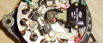
The generator stator is diagnosed after removal from the housing. First of all, carry out a visual inspection. There should be no visible damage to the wire or its insulation. Then connect the tester wire to the stator housing. With the second wire, touch the terminals one by one. There are only three of them. The tester must be in dialing mode. If the display shows infinity, this indicates that the stator is working properly.
Further testing consists of diagnosing the windings. The resistance of all three windings must be the same.
Instructions for rewinding a generator with your own hands
Stator repair involves rewinding the windings.
How to perform this procedure yourself:
- First of all, you need to disassemble the generator assembly and remove the stator from it.
- The existing windings must be burned so that they burn out, but before that you should count the number of turns and make an appropriate circuit for rewinding. In this case, on the stator it will be necessary to mark the locations of the terminals for the beginning and end of the winding. Don’t be afraid to burn it, this will not damage the iron and its magnetic characteristics will not be disrupted.
- After combustion, cleaning is carried out.
- Next, using materials such as syntoflex or press span, it is necessary to cut insulating gaskets. Please note that they should protrude from the ends of the groove by approximately 2.5-3 mm. When one of the gaskets is made and adjusted to size, a piece of tape will need to be cut according to its width or length. Then, using this spacer, cut 36 pieces of the same length and install them in the grooves.
- Then rewinding occurs. The essence of rewinding is that the wiring from one groove goes straight into the fourth, as if in a wave. Having wound half of the turns in one phase, winding is done in the opposite direction, and you need to cover the empty parts of the half-coils. All phases are wound in the same way.
- When the phases are rewound, you will need to seal the grooves by installing the protruding parts of the spacers in them. It is necessary to ensure that the protruding parts of the half-coils do not protrude beyond the boundaries of the metal inward, as well as beyond the boundaries of the fastening from the outside. To do this, tap the coils through the spacers.
- At this stage, you can check and try on the stator in the cover of the generator unit, make sure that the windings do not touch the housing. If there is a touch, then you need to get rid of it.
- Clean and connect the leads of the winding elements; to do this, twist them together and solder them. They will also need to be insulated; for this you can use a textile cambric.
- Before direct connection, you need to make sure that there is no short circuit between the phases, as well as to the metal. If there is a short circuit, then it is necessary to locate the contact point and then insulate it; this will require another gasket.
- After completing these steps, you will need to tie the winding element and secure its contacts with a cord thread. If you don’t have it, you can use linen thread, but not nylon thread, otherwise it will melt and flow when drying. The stator mechanism needs to be warmed up a little, this is done to dry it, and then place it in a container with impregnating varnish or a similar substance. Furniture varnish cannot be used.
- When the device is soaked, hang it up and wait a while until all the varnish has drained. Then it is recommended to place the device in the oven of a regular stove, which needs to be set to minimum heat; it would be better to hang it, and install an old tile under it. Or something similar, the main thing is that the varnish does not flow onto the hot tray. Wait about one hour - if during this time the varnish stops sticking, then at the same temperature you will need to dry the device for about 2 more hours.
Photo gallery “Independent stator rewinding”
1. Burn and remove old insulation.
2. Prepare the stator and install gaskets.
3. Start rewinding, the wire is laid in a “wave” from one groove to the fourth.
4. Wind all three phases.
5. Secure the leads using cord thread.
6. Open the stator with varnish, dry it and install it in the generator.
Checking the rotor winding (excitation) and stator winding of the generator
Checking the rotor field windings
First we remove and disassemble the generator. To independently check the rotor winding, you will need an ohmmeter (or a multimeter whose rotary switch position will be in resistance measurement mode, range up to 200 Ohms).
Part 1: Checking the rotor winding resistance. We touch the rotor rings with the measuring device:
- - if the winding resistance is within 1.8. 5 Ohm, then the rotor is working.
- - if the resistance is infinitely large, then the excitation winding circuit is broken.
- - if the resistance is below 1.8 Ohm, then there are short-circuited turns.
Most often, a rupture occurs at the place where the winding leads are soldered to the rings. The check can be carried out with a needle, moving the winding leads at the place where they are soldered. Darkening and shedding of insulation can be detected visually; this indicates combustion of the winding, which leads to a break or an interturn short circuit in the winding with a decrease in its total resistance.
Direct hydrogen cooling of turbogenerators
An even greater effect compared to indirect hydrogen cooling is provided by direct (internal) cooling, when hydrogen is supplied inside the hollow conductors of the winding.
TVF series generators use indirect cooling of the stator windings with hydrogen and direct (forced) cooling of the rotor windings. The ventilation system for the rotors of the TVF series generators is shown in Fig. 5.
Fig.5. Design of the ventilation duct in the rotor winding with direct cooling a - longitudinal section; b and c - transverse oblique sections along the rotor groove
Cooling gas is taken from the gap with subsequent release of the heated gas back into the gap. In this case, the conductors 1 of the rotor winding are made of solid rectangular cross-section, and oblique ventilation channels 2 are milled on their side surfaces. When the generator operates (rotor rotates), hydrogen enters the intake hole 3 and, passing through the oblique ventilation channel to the bottom of the groove 4, exits with the other side of the groove (coil) into another channel and through the outlet 5 enters the gap again.
Generators of the TGV series with a power of 200 and 300 MW have a slightly different rotor cooling system. Hydrogen circulates in axial rectangular channels, which are formed by trough-shaped conductors of the excitation winding.
Generators of this type also provide direct cooling of the stator windings. Hydrogen is supplied to thin-walled tubes made of non-magnetic steel, embedded inside the winding rods (Fig. 6) and open at the frontal parts.
Fig.6. Section of the stator groove (a) and rotor (b) of the generator type TGV 1 - groove wedge, 2 - body insulation; 3 - massive elementary conductor; 4 - gas tubes; 5 — rotor barrel; 6 — duralumin wedge; 7—sub-wedge insulation; 8 - half-turns of the winding; 9 - horizontal ventilation duct
In both types of generators (TGV and TVF), the hydrogen pressure in the housing is maintained at 0.2-0.4 MPa.
Generators with direct hydrogen cooling cannot operate on air cooling, since the winding, designed for forced cooling with hydrogen, will overheat and fail when operating on air cooling. Therefore, when large hydrogen leaks occur from the generator, accompanied by a deep and rapid decrease in hydrogen pressure, the direct-cooled generator must be emergency unloaded and disconnected from the network. A disconnected generator can be connected to the network only after the leaks have been eliminated and it has been switched to hydrogen, if it was switched to air to find leaks.
Stories from our readers
“Fucking basin. "
Hi all! My name is Mikhail, now I’ll tell you a story about how I managed to exchange my two-wheeler for a 2010 Camry. It all started with the fact that I began to be wildly irritated by the breakdowns of the two-wheeler, it seemed like nothing serious was broken, but damn it, there were so many little things that really started to irritate me. This is where the idea arose that it was time to change the car to a foreign car. The choice fell on the melting Camry of the tenth years.
Yes, I had matured morally, but financially I just couldn’t handle it. I’ll say right away that I am against loans and taking a car, especially not a new one, on credit is unreasonable. My salary is 24k a month, so collecting 600-700 thousand is almost impossible for me. I started looking for different ways to make money on the Internet. You can’t imagine how many scams there are, what I haven’t tried: sports betting, network marketing, and even the volcano casino, where I successfully lost about 10 thousand ((The only direction in which it seemed to me that I could make money was currency trading on the stock exchange, they call it Forex. But when I started delving into it, I realized that it was very difficult for me. I continued to dig further and came across binary options. The essence is the same as in Forex, but it’s much easier to understand. I started reading forums, studying trading strategies. I tried it on a demo account, then opened a real account. To be honest, I didn’t manage to start earning money right away, until I understood all the mechanics of options, I lost about 3,000 rubles, but as it turned out, it was a precious experience. Now I earn 5-7 thousand rubles a day. I managed to get the car buy after half a year, but in my opinion this is a good result, and it’s not about the car, my life has changed, I naturally quit my job, I have more free time for myself and my family. You’ll laugh, but I work directly on the phone)) If If you want to change your life like me, then here’s what I advise you to do right now: 1. Register on the site 2. Practice on a Demo account (it’s free). 3. As soon as you get something on the Demo account, top up your REAL ACCOUNT and go to REAL MONEY! I also advise you to download the application to your phone, it’s much more convenient to work from your phone. Download here.
Checking the stator winding
We visually check that there is no cracking of the insulation and no burning of the winding (occurs when there is a short circuit in the valves of the rectifier unit). A stator with a damaged winding should be replaced.
A problem with the winding is not the only cause of generator failure. You will find other tips in the DIY generator repair section.
Have you ever had to check the rotor and stator windings of a generator yourself?
Signs of generator failure
Signs of abnormal operation of a car generator may include:
- no “battery” indication on the dashboard when the ignition is turned on;
- the “battery” light glows after starting the engine;
- periodic blinking of the “battery” signal indicator while driving;
- the smell of burnt electrical wiring in the generator area;
- failure to start the engine after parking.
Lack of battery charge with a faulty generator leads to problems with starting the engine. More dangerous is a malfunction associated with exceeding the current and voltage of the car battery charge. Many car enthusiasts use a donor battery to start the engine, after which they disconnect the battery terminals to switch to charging their own battery. At this moment, the vehicle's electrical equipment is powered by a generator.
If the generator is faulty, the voltage in the on-board network may be more than 17 volts, which leads to breakdown of the protective zener diodes in the engine control unit. In this case, expensive repairs to the engine control unit are required.
Basic circuits
| Figure 1. Multivibrator on logic inverters. |
To build the generator, the circuit of a self-oscillator based on two logical inverters is taken as a basis (Figure 1). The principle of its operation is based on periodic recharging of the capacitor. The moment of switching the state of the circuit is determined by the degree of charge of capacitor C1. The recharging process occurs through resistor R1. The larger the capacitance C1 and the resistance R1, the longer the process of charging the capacitor takes place, and the longer the duration of the switching periods of the circuit state. And vice versa.
To construct the generator circuit, a microcircuit with four 2I-NOT elements - HEF4011BP - was taken as logic elements
The basic circuit shown above produces a square wave signal at the Q output of a fixed frequency and a duty cycle of 50% (square wave). To expand the capabilities of the device, it was decided to combine three different circuits in it, implemented on the same two logical inverters
Square wave generator circuit
The square wave generator circuit is shown in Figure 2-a. The timing capacitance of the circuit can vary from the value of C1 to the total value of C1 and the capacitance connected by jumper P. This allows you to change the frequency range of the generated signal.
| Figure 2. Schematic diagrams of generators based on logical inverters. |
Resistor R1 allows you to smoothly change the charge (recharge) current of the capacity. Resistor R2 is current-limiting, to avoid overloading the output channel of logic element DD1.1 in the case when the slider of resistor R2 is in the uppermost position and its resistance is close to zero. Since the charging and recharging of the capacitor is carried out along the same chain with unchanged parameters, the duration of the pulse and the pause between them are equal. Such a signal has a symmetrical rectangular shape and is called a meander. By adjusting R1, only the frequency of the generated signal changes in a certain range specified by the timing capacitor.
In Figure 2-b, the charging circuit and the recharging circuit are separated by diodes VD1 and VD2. If a pulse is formed during the charging of a timing capacitor, its duration is characterized by the resistance of the VD1-R2-R1 chain. The duration of the pause between pulses during reverse recharging of the capacity is characterized by the resistance of the circuit R1-R3-VD2. Thus, by changing the position of the sliders of resistors R2 and R3, you can smoothly and separately set the duration of the pulse and the pause between them.
The frequency range of the generated signal, as in the first case, is switched by jumper P.
PWM generator circuit
The circuit in Figure 2-c has a similar separation of the direct and reverse charging circuits of the timing capacitance, with the difference that the variable resistances are the arms of the variable resistor R2, which have an inverse dependence of the parameters in relation to each other. That is, as one arm of the resistor increases, the second one decreases in direct proportion, and the total sum of their resistances is constant. Thus, by adjusting the ratio of the arms of resistor R2, you can smoothly change the ratio of the duration of the pulses to the duration of the pauses between them, and the time of the pulse repetition period will remain unchanged. This adjustment method allows you to implement the pulse width modulation (PWM) function
The frequency of the generated signal in this circuit is selected discretely by switching jumper P. If necessary, you can use several jumpers P to sum large and small capacitance values, achieving a more accurate required signal generation frequency within the entire range.
Initial check sequence
An initial performance check can be performed without dismantling the generator. To do this, set the multimeter switch to the “constant voltage 20V” mode. Next, connect the black probe to the negative terminal of the battery, the red one to the positive terminal. After this, you need to start the engine and let it reach a stable idle speed. Multimeter readings ranging from 13.5 to 14.5 Volts are considered normal.
If the multimeter shows a value less than 12.8 Volts, the charging process either does not occur at all, or the charging current is extremely small. The generator is operating in abnormal mode. When the voltage is more than 14.8 Volts, the battery is overcharged. This can lead to boiling of the electrolyte, an increase in acid concentration, and destruction of the battery plates.
To check the voltage at the generator output, you need to turn on the car lamp in the open circuit from terminal 30 on the generator (the point of contact with the thick wire leading to the positive terminal of the battery or starter).
Next, connect the multimeter in the “=20V” mode with the red probe to contact 30 of the generator, and the black probe to the stripped contact on the engine or body. Start the engine. The reading on the multimeter should not be more than 15.5 volts whenever the accelerator pedal is pressed. Otherwise, further operation of the generator is dangerous for the electrical equipment of the car.
When checking, you should evaluate the degree of tension of the generator belt. Using a simplified method, this can be done by pressing on the belt with your finger.
The amount of deflection should be within 0.5 - 1 centimeter. At the same time, check the degree of belt wear. To determine the reasons for abnormal operation of the generator and perform repair work, dismantling the generator is required.
Final generator circuit
Figure 3 shows a generator circuit in which all three circuits discussed in Figure 2 are implemented. The generator is based on two logical inverters based on elements DD1.1 and DD1.2. The selection of the frequency range (frequency in PWM mode) is carried out by switching jumper P.
| Figure 3. Square-wave generator circuit. |
To assemble the desired version of the generator circuit, pin connectors are introduced, switched by parallel assemblies of jumpers, shown as colored lines. Each jumper color corresponds to its own connection diagram. The jumpers are implemented by connecting pairs of contacts with wires from the connector cable of type FC-10P A. The pin connectors themselves are located in three groups of five pairs for ease of switching. The jumper connector allows you to switch the generation mode.
Elements DD1.3 and DD1.4 act as inverting repeaters and serve to decouple the timing and output circuits of the generator to eliminate their mutual influence. The inverted signal is taken from output DD1.3, and the main signal from output DD1.4.
Resistors R5 and R6 are used to adjust the voltage level of the pulses of the corresponding channels. Transistors VT1 and VT2 are connected in an emitter follower circuit to amplify the signals taken from the sliders of resistors R5 and R6, respectively. Transistors VT3 and VT4 bypass the output circuits of their channels, pulling them to the power supply negative. Their role is important when applying a generator signal to a load with a capacitance present, when a discharge of this capacitance is necessary during a dead pause, as for example when controlling field-effect transistors. Diodes VD5 and VD6 separate the base circuits of the shunt transistors from the generator output, eliminating the influence of capacitive load on the operation of these transistors. Resistors R9 and R10 are necessary to match the generator outputs with a load resistance of 50 Ohms, as well as to limit the maximum current of the transistors of the channel output stages.
Diode VD3 protects the circuit from connecting the supply voltage with reverse polarity. The VD4 LED acts as a power indicator. Capacitor C21 partially smoothes out ripple when powered from an unstabilized source.