Since the engine requires electricity to operate, and the battery reserve is only enough to start it, the car’s generator is constantly producing it at idle and at high speeds. In addition to supplying voltage to all consumers of the on-board network, electricity is spent on recharging the battery and self-excitation of the generator armature.
Rice. 1 Auto generator
Purpose of a car generator
In addition to powering the on-board network, the car's generator replenishes the amount of electricity that was consumed by the battery when starting the internal combustion engine. The initial excitation of the winding is also carried out due to the direct current of the battery. The generator then begins to generate electricity on its own when the rotation is transmitted by a belt to a pulley from the engine crankshaft.
In other words, without a generator, the car will start with the starter from the battery, but it will not go far, and will not start next time, since the battery will not receive a recharge. The operating life of the generator is influenced by the following factors:
- battery capacity and amperage;
- driving style and mode;
- number of on-board network consumers;
- seasonality of vehicle operation;
- quality of manufacture and assembly of generator components.
The simple design allows you to diagnose and repair most breakdowns yourself.
The principle of operation of a car generator
By the nature of its operation, an autogenerator resembles an ordinary electric motor, but the principle of its operation is diametrically opposite: if an ordinary motor converts energy into mechanical movement, then the generator, receiving a rotating impulse from the internal combustion engine, converts it into electricity.
The operating principle of a car generator is approximately the following. After turning the key in the ignition switch, voltage is applied to the rotor winding, it passes through the slip rings and the brush block. As a result, a magnetic field appears around the winding. This field constantly rotates with the motor rotor, while interacting with the stator windings. A current appears on the stator winding, which is supplied to the diode bridge. At the output of the diode bridge, the current already has a stable value. Next, the current is supplied to the voltage regulator, after which it is used to power consumers and the battery.
An important element in the operation of a car generator is the voltage regulator relay. It is necessary to maintain the required current values supplied to the battery. Without the use of a regulator, as the engine speed increased, the alternator would create excess voltage, which could damage the battery. This relay also provides thermal compensation - at low temperatures, increased voltage is supplied to the battery, and as operating temperatures increase, the voltage will decrease.
Design Features
The operating principle of a car generator is based on the effect of electromagnetic induction, which makes it possible to receive an electric current by inducing and then changing the magnetic field around the conductor. To do this, the generator contains the necessary parts:
- rotor - a coil inside two pairs of multidirectional magnets, receiving rotation through a pulley, and direct current to the field windings through brushes and commutator rings
- stator - windings inside the magnetic circuit in which alternating electric current is induced
- diode bridge – rectifies alternating current into direct current
- voltage relay - regulates this characteristic within 13.8 - 14.8 V
Rice. 2 Generator design
When the engine is not running, at the moment of starting it, the excitation current is supplied to the armature from the battery. Then the generator begins generating electricity on its own, switches to self-excitation, and completely restores the battery charge while the car is moving.
At idle speed, recharging does not occur, but the on-board network and all its consumers (headlights, music, air conditioning) are provided in full.
Stator
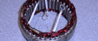
The most complex part of a generator is the stator structure:
- from transformer iron 0.8 - 1 mm thick, plates are cut out with a stamp;
- packages are assembled from them (welding or fastening with rivets), 36 grooves around the perimeter are insulated with epoxy resin or polymer film;
- then 3 windings are placed in bags, fixed in the grooves with special wedges.
Rice. 3 Generator stator
It is in the stator that alternating voltage is generated, which the car generator later rectifies into direct current for the on-board network and battery.
Rotor
When using rolling bearings, the journal is hardened, and the shaft itself is created from alloy steel. A coil covered with a special dielectric varnish is wound on the shaft. Magnetic pole halves are placed on top of it and secured to the shaft:
- look like a crown;
- contain 6 petals;
- are made by stamping or casting.
Rice. 4 Generator rotor
The pulley is fixed on the shaft with a key or a nut with a hex key. The power of the generator depends on the thickness of the excitation coil wire and the quality of the varnish insulation of the windings.
When voltage is applied to the field windings, a magnetic field appears around them, interacting with a similar field from the permanent pole halves of the magnets. It is the rotation of the rotor that ensures the generation of electric current in the stator windings.
Current collection unit
In a brush generator, the structure of the current collection unit is as follows:
- the brushes slide along the commutator rings;
- they transmit direct current to the excitation winding.
Electrographite brushes wear out less than copper-graphite modifications, but a voltage drop is observed on the collector half-rings. To reduce electrochemical oxidation of rings, they can be made of stainless steel and brass.
Rice. 5 Generator current collection unit
Since the operation of the current collection unit is accompanied by intense friction, brushes and commutator rings wear out more often than other parts and are considered consumables. Therefore, they are quickly accessible for periodic replacement.
Rectifier
Since the stator of an electrical appliance generates alternating voltage, and the on-board network requires direct current, a rectifier is added to the design, to which the stator windings are connected. Depending on the characteristics of the generator, the rectifier unit has a different design:
- the diode bridge is soldered or pressed into horseshoe-shaped heat sink plates;
- The rectifier is assembled on a board, heat sinks with powerful fins are soldered to the diodes.
Rice. 6 Generator rectifier
Rice. 7 Diode bridge option with independent radiators
The main rectifier can be duplicated by an additional diode bridge:
- sealed compact unit;
- dida-pea or cylindrical shape;
- inclusion in the overall scheme by small buses.
The rectifier is the “weak link” of the generator, since any foreign body that conducts current, accidentally falling between the heat sinks of the diodes, automatically leads to a short circuit.
Voltage regulator
After the alternating amplitude is converted into direct current by the rectifier, the generator power is supplied to the voltage regulator relay for the following reasons:
- The internal combustion engine crankshaft rotates at different speeds depending on the type of driving, travel distance and vehicle driving cycle;
- therefore, a car generator by default is not physically capable of producing the same voltage at different periods of time;
- The regulator relay device is responsible for temperature compensation - it monitors the air temperature, and when it decreases, it increases the charging voltage and vice versa.
The standard temperature compensation value is 0.01 V/1 degree. Some generators have manual summer/winter switches that are located in the interior or under the hood of the car.
Rice. 8 Voltage regulator
There are voltage regulator relays in which the on-board network is connected to the generator excitation winding with a “–” wire or “+” cable. These designs are not interchangeable, they cannot be confused; most often, “negative” voltage regulators are installed in passenger cars.
Bearings
The front bearing is considered to be on the pulley side, its housing is pressed into the cover, and a sliding fit is used on the shaft. The rear bearing is located near the collector rings; on the contrary, it is mounted on the shaft with interference; a sliding fit is used in the housing.
In the latter case, roller bearings can be used; the front bearing is always a radial ball bearing with a one-time lubricant applied at the factory, which is enough for the entire service life.
Rice. 9 Generator bearing kit
The higher the generator power, the greater the load the bearing race experiences, and the more often both consumable parts need to be replaced.
Impeller
The friction parts inside the generator are cooled by forced air. To do this, one or two impellers are placed on the shaft, sucking air through special slots/holes in the product body.
Rice. 10 Generator impeller
There are three types of air-cooled car generators:
- if there is a brush/collector ring assembly and the rectifier and voltage regulator are moved out of the housing, these components are protected by a casing, so air intake holes are created in it (position a) of the lower circuit;
- if the arrangement of the mechanisms under the hood is dense, and the air surrounding them is too hot to properly cool the internal space of the generator, a specially designed protective casing is used (position b) in the lower figure;
- in small-sized generators, air intake slots are created in both housing covers (position c) in the bottom figure).
Rice. 11 Options for generator air cooling schemes
Overheating of the windings and bearings sharply reduces the performance of the generator, and can lead to jamming, short circuit and even fire.
Frame
Traditionally, for most electrical appliances, the generator housing has a protective function for all components located inside it. Unlike a car starter, the generator does not have a tensioner; the sagging of the transmission belt is adjusted by moving the housing of the generator itself. For this purpose, in addition to the mounting tabs, the body has an adjustment eye.
The body is made of aluminum alloy and consists of two covers:
- The stator and armature are hidden inside the front cover;
- Inside the back cover there is a rectifier and a voltage regulator relay.
Rice. 12 The generator housing consists of two covers
The correct operation of the generator depends on this part, since a rotor bearing is pressed inside one cover, and the belt is tensioned in the eye of the housing.
The device of a car generator
Main parts of the generator
Generator in section
Stator and rotor
The stator (the stationary part of the generator) is a winding with a magnetic core in which electric current is generated. The rotor is the rotating part of the generator. The rotor consists of field windings with a pole system, a shaft and slip rings. Rings are most often made of copper, crimped with plastic. They can be made from brass or stainless steel to reduce wear and prevent oxidation. The leads of the excitation winding are connected to the rings. Power is supplied to the windings through brushes (sliding contacts), which are pressed against the rings using springs. There are two types of brushes: copper-graphite and electrographite. The latter have a higher electrical resistance, which reduces the output characteristics of the generator, but they provide significantly less wear on the slip rings. There are also brushless generators that have permanent magnets on the rotor and field windings on the stator. The absence of brushes and slip rings increases the reliability of the generator, but increases weight and noise during operation.
When the rotor rotates opposite the stator winding coils, alternately polarized poles appear, i.e., the direction and magnitude of the magnetic flux penetrating the coil changes, which leads to the appearance of an alternating voltage in it. Since consumers of the vehicle's electrical network operate at constant voltage, a diode rectifier is introduced into the generator circuit.
Diode bridge and voltage regulator
Design and drive of generators
Electronic voltage regulators are usually built into the generator (“tablet”) and combined with the brush assembly. Sometimes they are located separately in the engine compartment. Regulators change the excitation current by changing the time the rotor winding is switched on to the supply network. The devices are maintenance-free; you only need to monitor the reliability of the contacts. There are voltage regulators equipped with a temperature compensation function - they change the charging voltage depending on the air temperature in the engine compartment to ensure optimal battery charging. The lower the air temperature, the more voltage is supplied to the battery, and vice versa.
Generators are available in two designs - “classic”, with a fan at the drive pulley, and compact, with two fans inside the generator. Since “compact” generators have a drive with a higher gear ratio, they are also called high-speed generators.
The generator is mounted on a special engine bracket and is driven from the crankshaft pulley through a belt drive. The larger the diameter of the pulley on the crankshaft and the smaller the diameter of the generator pulley, the higher the generator speed, and accordingly, it is able to deliver more current to consumers. On modern models, as a rule, the drive is carried out by a poly-V-belt. Due to its greater flexibility, it allows the installation of a small diameter pulley on the generator. The generator can be driven either separately or by one belt together with a coolant pump (“pump”). Belt tension is regulated either by deflection of the generator housing, or (in the case of using a poly-V-belt) by tension rollers when the generator is stationary.
Is it possible to replace a generator of one brand with another? Complete if the following conditions are met:
- the energy characteristics of the replacement generator are not lower than those of the one being replaced;
- the gear ratio from the engine to the generator is the same;
- The overall and mounting dimensions of the replacement generator allow it to be installed on the engine. Most foreign-made generators have a single-leg mount, while domestic ones are fastened with two legs, so replacing a “foreign” generator with a domestic one will require replacing the bracket;
- The electrical circuits of the generator sets are similar.
Operating modes
When operating the machine generator, there are 2 modes:
- starting the internal combustion engine - at this moment the car starter and the generator rotor coil are the only consumers, battery energy is consumed, starting currents are much higher than operating currents, so whether the car starts or not depends on the quality of battery recharging;
- operating mode - the starter is switched off at this moment, the generator rotor winding goes into self-excitation mode, but other consumers appear (air conditioning, glass heaters, mirrors, headlights, car audio), it is necessary to restore the battery charge.
Attention: With a sharp increase in the total load (audio system with an amplifier, subwoofer), the generator current becomes insufficient to meet the needs of the on-board system, and the battery charge begins to be consumed.
Therefore, to reduce voltage sags, car audio owners often install a second battery, increase the power of the generator, or duplicate it with another device.
Rice. 13 Two generators on one car
Generator drive
The alternator receives speed to generate electricity via a V-belt drive from the engine crankshaft. Therefore, the belt tension should be checked regularly, preferably before each trip. The main nuances of the generator drive are:
- the tension is checked with a force of 3–4 kg, the deflection in this case cannot exceed 12 mm;
- diagnostics is carried out with a ruler, the force to one edge of which is provided by a household steelyard;
- the belt may slip if oil gets on it due to leaks in gaskets and seals in adjacent units under the hood;
- an overly stiff belt causes increased wear of the bearings;
- Lack of alignment of the crankshaft pulleys and the generator leads to whistling and uneven belt wear in the cross section.
Rice. 14 Generator drive
The average resource of pulleys is 150 - 200 thousand kilometers of car mileage. This characteristic of a belt varies too much depending on the manufacturer, car model, and driving style of the owner.
History of the car generator
Michael Faraday
The history of the automobile generator begins approximately 200 years ago. The origins of this story lie back in 1831, when the English physicist Michael Faraday and the American physicist Joseph Henry discovered the phenomenon of electromagnetic induction. Now this phenomenon is known as Faraday's law, but that's not what this article is about. Approximately the meaning of this law can be expressed as follows: Electromotive force is generated in an electrical conductor, which surrounds a changing magnetic flux . Having discovered the law of electromagnetic induction, Michael Faraday decided to build a visual model of his law. Now known as the Faraday Disc , it was the first device to convert mechanical motion into electrical energy. Thus, we can consider this device to be the first generator. The Faraday Disc itself was extremely ineffective, but it was of great importance for the development of science and industry in general.
Faraday disk
Rumors of Faraday's law began to spread and already in 1832, French instrument maker Hippolyte Pixie built the world's first dynamo generator. His model created electrical impulses separated by the absence of current. Thus, he accidentally created an alternator. Since he didn't know what to do with it (variable current), Pixie decided to get rid of alternating current and focus on direct current. The ultimate goal of such a generator was to use it in industry, but this was not possible, since the Pixie generator was quite difficult to use. To generate electricity, you need to constantly rotate a heavy magnet by hand.
Electrical diagram
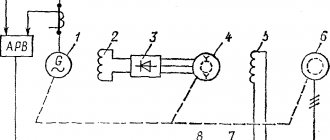
Manufacturers take into account the specific number of consumers in a car model, so in each case an individual electrical circuit of the generator is used. The most popular are 8 diagrams of “mobile electrical installations” under the hood of a car with the same designation of elements:
- generator block;
- rotor winding;
- stator magnetic circuit;
- diode bridge;
- switch;
- lamp relay;
- regulator relay;
- lamp;
- capacitor;
- transformer and rectifier unit;
- battery;
- Zener diode;
- resistance.
Rice. 15 Scheme 1
In schemes 1 and 2, the exciting winding receives voltage through the ignition switch so that the battery does not discharge when parked. The disadvantage is the switching of 5 A current, which reduces the service life.
Rice. 16 Scheme 2
Therefore, in diagram 3, the contacts are unloaded by the intermediate relay, and the current consumption is reduced to tenths of an ampere. The disadvantage of this option is the complex installation of the generator, decreased reliability of the design, and the switching frequency of the transistor increases. The headlights may blink and the instrument needles may shake.
Rice. 17 Scheme 3
In circuit 5, an additional rectifier is made from three diodes on the way to the excitation winding. However, when parking for a long time, it is recommended to remove the “+” from the battery terminal, as the battery may be discharged. But during the initial excitation of the winding at the moment of starting the internal combustion engine, the battery current consumption is minimal. Extinguish the zener diode, which is dangerous for the electronics of the machine.
Rice. 18 Scheme 5
For diesel engines, generators using circuit 6 are used. They are designed for a voltage of 28 V; the exciting winding receives half the charge due to connection to the “zero” point of the stator.
Fig 19 Scheme 6
In diagram 7, the discharge of the battery during long-term parking is eliminated by reducing the potential difference at the “D” and “+” terminals. An additional wing of the rectifier diode bridge was created from zener diodes to eliminate voltage surges.
Rice. 20 Scheme 7
Scheme 8 is usually used in Bosch generators. Here the voltage regulator is complicated, but the circuit of the generator itself is simplified.
Rice. 21 Scheme 8
Terminal markings on the housing
When performing self-diagnosis with a multimeter, the owner needs relevant information on how the terminals on the generator housing are marked. There is no single designation, but general principles are followed by all manufacturers:
- a “plus” comes out from the rectifier, marked “+”, 30, B, B+ and BAT, a “minus”, marked “–”, 31, D-, B-, E, M or GRD;
- terminal 67, Ш, F, DF, E, EXC, FLD departs from the exciting winding;
- the “positive” wire from the additional rectifier to the control lamp is designated D+, D, WL, L, 61, IND;
- the phase can be recognized by a wavy line, the letters R, W or STA;
- the zero point of the stator winding is designated “0” or MP;
- the regulator relay terminal for connection to the “plus” of the on-board network (usually the battery) is designated 15, B or S;
- the cable from the ignition switch must be connected to the voltage regulator terminal marked IG;
- The on-board computer is connected to the regulator relay terminal marked F or FR.
Rice. 22 Location of terminals on the generator housing
There are no other designations, and the above ones are not fully present on the generator housing, since they are found on all existing modifications of electrical appliances.
Basic faults
Failures of the “on-board power plant” are caused by improper operation of the vehicle, exhaustion of friction parts, or failure of the electrics. First, visual diagnostics are carried out and extraneous sounds are identified, then the electrical part is checked with a multimeter (tester). The main faults are summarized in the table:
| Breaking | Cause | Repair |
| whistling, loss of power at high speeds | insufficient belt tension, bearing/bushing failure | tension adjustment, bushing/bearing replacement |
| undercharge | regulator relay is faulty | relay replacement |
| recharge | regulator relay is faulty | relay replacement |
| shaft play | bearing failure or bushing wear | replacement of consumables |
| current leakage, voltage drop | diode breakdown | replacing rectifier diodes |
| generator failure | burning or wear of the commutator, breakage of the excitation winding, stuck brushes, jamming of the rotor in the stator, breakage of the wire leading from the battery | eliminate the indicated breakdowns |
During diagnostics, the tester measures the generator voltage at different engine speeds - at idle, under load. The integrity of the windings and connecting wires, the diode bridge and the voltage regulator is checked.
How many volts should the generator produce?
For correct operation of the car, it is necessary to regularly check the functionality of the car generator. If this unit fails, the battery will no longer receive main power. This state of affairs (when the car is “powered” only by the battery) leads to a rapid loss of power to the entire car.
Timely monitoring of the technical condition of the electrical source will allow you to avoid accidental failure of the element, saving your money and mental strength.
The breakdown of the power unit generating current is determined by one of the following signs:
- The light on the dashboard is constantly on (signal of insufficient current);
- The battery constantly runs out;
- electrical equipment malfunctions or does not work at all when the engine is turned on;
- burning smell from the engine compartment;
- the stator overheats;
- The NODE makes uncharacteristic sounds (for example, rustling).
Choosing a generator for a passenger car
Due to the different diameters of the V-belt drive pulleys, the generator is given a higher angular speed compared to the crankshaft speed. The rotor rotation speed reaches 12 - 14 thousand revolutions every minute. Therefore, the generator resource is at least half that of an internal combustion engine car.
The machine is equipped with a generator at the factory, so when replacing, a modification with similar characteristics and mounting holes is selected. However, when tuning a car, the owner may not be satisfied with the power of the generator. For example, after increasing the number of consumers (heated seats, mirrors, windows), installing a subwoofer, an audio system with an amplifier, it is necessary to select a new, more powerful generator or install a second electrical appliance complete with an additional battery.
In the first case, you should select a power sufficient to recharge the battery with a 15% margin. When installing a second generator, the initial and operating budget increases dramatically:
- for an additional generator you will have to install an additional pulley on the crankshaft;
- find a place to mount the body of the electrical device so that its pulley is located in the same plane as the crankshaft pulley;
- maintain and change consumables of two “mobile power plants” at once.
With the advent of brushless generator models, some owners are replacing the standard device with this device.
Generator device
The pulley transmits energy from the motor to the shaft using a belt.
Covers on the housing are needed to accommodate the rotor supports, install the unit on the motor and secure the stator. The back cover is needed for the brush assembly and outputs for powering electrical equipment. The stator produces power through a three-phase winding. The rotor is a steel shaft with two bushings. The terminals of this winding are connected to copper rings. The regulator stabilizes the voltage under various factors:
- electrical load surges;
- rotor speed delta;
- temperature changes in nature.
