About the main elements of an electrical circuit
The vehicle's electrical circuit includes the following components:
- Sources of electrical energy.
- Devices responsible for its consumption.
Energy sources
The generator together with the battery is responsible for this function . The rotation of the generator will be forced while the engine is running. The voltage generated is much higher compared to the on-board network. It ranges from 13.2 to 14.7 Volts. This value is enough for a stable charge of the battery, providing the necessary voltage to all units inside the car. Thanks to this, any Chevrolet Niva electrical circuit works stably.
Consumers
These can be individual devices or whole blocks . It is assumed that each block is equipped with its own fuses. Thanks to this, systems become more reliable and secure.
Types of fuses with different resistance ratings are mounted , and they are combined in one place. The fuse box is standardly located inside the passenger compartment; almost all electrical circuits pass through it. The exception is those parts that are responsible for starting and charging engines.
The most powerful consumers are the following:
- Charger socket or cigarette lighter.
- Dashboard.
- Heated rear window with power windows and windshield wipers.
- Lighting. This includes all sources from which light comes. And those that work from the on-board network. Usually we are talking about low and high beam lamps, side lights, direction indicators, and so on.
- Starter. With his participation, the engine starts automatically using a special system of gears connected to the flywheel. 1.5 kW – rated current power, with a total power of 80A. A description of the exact characteristics is always in the official instructions.
In general, the scheme looks like this (see the video at the end of the article for details):
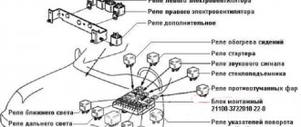
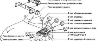
Designations for the electrical diagram of a Chevrolet Niva car - engine 2123:
1 — right headlight; 2 — sound signal; 3 — engine compartment lamp; 4 — engine compartment lamp switch; 5 - starter; 6 - battery; 7 - generator; 8 — air temperature sensor; 9 — left headlight; 10 — power window switch for the right front door; 11 — gear motors for electric windows; 12 — switch for interior lighting in the door lock; 13 — gear motor for door lock; 14 — connection block to the right front speaker of the audio system; 15 — heater electric motor; 16 — speed sensor; 17 — windshield washer electric motor; 18 — windshield wiper electric motor; 19 - switch for interior lighting in the driver's door lock; 20 — gear motor for locking the driver’s door lock; 21 — brake fluid level sensor; 22 — connection block to the left front speaker of the audio system; 23 — power window switch of the right front door; 24 — left front door power window switch; 25 — mounting block; 26 — relay for turning on electric windows; 27 — relay for turning on the sound signal; 28 — diagnostic block; 29 — control unit for the door lock system; 30 — connection block to the wiring harness of the front seat heating system; 31 — connection block to the injection system wiring harness; 32 — instrument cluster; 33 — right side turn signal; 34 — glove box lighting lamp; 35 — switch for the glove compartment lighting lamp; 36 — ignition switch; 37 — brake signal switch; 38 — reverse light switch; 39 — control lamp block; 40 — electric headlight range control regulator; 41 — instrument lighting regulator; 42 — steering column switch; 43 — left side direction indicator; 44 — heater motor switch; 45 — additional resistor of the heater electric motor; 46 — parking brake sensor; 47 — rear fog light switch; 48 — fog lamp switch; 49 — rear window heating switch; 50 — external lighting switch; 51 — alarm switch; 52 — connection block to the right rear speaker of the audio system; 53 — electric fuel pump with fuel level sensor; 54 — backlight lamps for heater control levers; 55 — differential lock activation sensor; 56 — cigarette lighter; 57 — backlight lamp; 58 — control unit for the automobile anti-theft system; 59 — interior lamp; 60 — canopy for individual interior lighting; 61 — connectors for connecting to the head unit of the audio system; 62 — connection block to the left rear speaker of the audio system; 63 — right rear light; 64 — trunk lighting; 65 — license plate lights; 66 — tailgate glass washer motor; 67 — tailgate glass wiper motor; 68 — rear door glass heating element; 69 — additional brake signal; 70 - left rear light
1.19. Heating and ventilation
The recirculation damper mechanism is dismantled and the cable is removed. Each end must be twisted into a ring and securely fixed.
Using a cable, the position of the air supply flap is changed. Assembly is carried out in the reverse order. Replacing the interior heating control unit A faulty control unit can also cause incorrect operation of the interior heating system. Its dismantling, necessary for repair or replacement, requires the following procedure. The negative terminal is disconnected from the battery. All handles are removed from the heater control mechanism.
To do this, you need to carefully pull them towards you. All handles are removed from the heater control mechanism. Use a flat screwdriver to remove the air circulation lever.
Use a flat screwdriver to remove the air circulation lever. Use a screwdriver to pry up and then remove the block lining. Use a screwdriver to pry up and then remove the block lining. Under the lining, use a Phillips screwdriver to unscrew two self-tapping screws.
Under the cladding, two self-tapping screws are unscrewed. The control unit is removed. Remove the connector with the wires going to the speed switch. The block of wires that provide illumination of the unit is disconnected. The connector with wires is removed from the control unit. If there is an air conditioner, all hoses coming from the vacuum switch are disconnected.
Use a screwdriver to remove the bracket holding the damper cable braid and other similar elements. All rods are disconnected from the control unit. A new or repaired device is installed in the reverse order.
After dismantling, the control unit is repaired or replaced with a new one. Replacing the stove pipes If a coolant leak is detected, the pipes along with the clamps should be replaced. The work is performed in the following sequence: The coolant is drained from the system.
The screws securing the glove compartment are unscrewed and it is removed. Use a Phillips screwdriver to unscrew the clamp of the lower pipe. The hose is removed carefully - the antifreeze should not get on exposed skin. If difficulties arise, the pipe should be rotated around its axis. Correctly turning on the foot airflow It turns out that even after several years of owning a Chevrolet Niva, not everyone knows how to properly turn on the warm air airflow to the feet.
By using fan speed controls and damper position controls, and using sound logic, we can end up with a situation where the entire flow of hot air is directed onto the windshield and into the face of the driver and front passenger. Of course, the car is warm, even hot, but your feet are cold.
Practice has shown that Shniva has a special algorithm for supplying hot air to the legs. On most copies this is done like this: Warm up the engine until the flow of warm air is clearly felt by your hand.
Also interesting: Niva 4x4 jungle camouflage - Auto Magazine
The fan speed switch is set to the fourth position, 4th speed. Turn the airflow direction knob to exactly 12 o'clock. Immediately return it to the position around the clock. Correct position of the stove blower control. The air damper will make a characteristic click and the air flow will flow to your feet.
Exceptions are the heater valve built into the partition of the engine compartment, and the pipes connecting the heater to the engine cooling radiator. If necessary, this unit can be replaced entirely.
The radiator and heater dampers are combined into a single unit: The air forced by the heater fan enters the heating system through the air intake located under the windshield.
Depending on the position of the damper, the air flow goes either through the heater radiator or directly into the air ducts. The distribution damper is responsible for distributing the flow between the air ducts. The selection of the stove operating mode, temperature and air flow direction is made using the stove control unit located on the center console.
Heating system with air conditioning The principle of operation of a car heater with air conditioning is similar to that described above. However, its design is significantly different. Instead of an intermediate heater housing, an air conditioner evaporator is installed, hidden by a plastic casing. When the air conditioner is turned on, air is supplied to the cabin through the evaporator using a damper.
The design of a car heater with air conditioning is somewhat different: To carry out high-quality repairs, you first need to understand the reasons and identify the faulty element of the system. The stove does not heat the footwell. There may be several reasons why the stove does not direct air to the feet.
First you need to find out whether this mode is turned on correctly. Due to the design features of the damper system, the direction of air to the legs is carried out as follows: Set the fourth rotation speed of the stove fan. Set the heater mode switch to the upper vertical position. Switch the mode controller one position to the left.
After this, air should begin to flow into the legs. If this does not happen, the procedure should be repeated several more times. If the mode still does not turn on, you should check the following components: Coolant leak If antifreeze leaks from the cooling system without visible streaks on the radiator and pipes, you need to pay attention to the condition of the heating system. The main signs of a coolant leak through the heater are: Typically, the leak occurs through the heater radiator.
To verify this, you need to remove the lower part of the center console. If traces of moisture are detected in the area of the stove body, it is recommended to replace the radiator.
If a coolant leak is detected through the heater radiator, it should be replaced. Before replacing the heater radiator, you should check the tightness of the heater pipes and their connections. The stove does not warm up the air well. Often the stove does not warm up the interior effectively enough. Instead of hot air, slightly warm or even cool air comes from the deflectors. This usually happens for the following reasons: Thus, when diagnosing a malfunction, first check the coolant level in the cooling system.
If it is insufficient, they begin to look for leaks. If the stove cannot melt the ice on the windshield, it is faulty. If the amount of antifreeze is OK, and the stove does not respond to changes in the position of the temperature regulator, the damper is faulty.
With proper diagnosis, this will not be difficult. Replacing damper control cables Damper control cables fail quite often. Usually the cable braid is damaged, which leads to the need to replace the entire part.
You can purchase suitable cables at almost any auto parts store. When choosing a new heater cable, you should pay attention to its length. To replace the cables, you only need flat-blade and Phillips-blade screwdrivers.
Read news about the new Niva
- Refinement of the Chevrolet Niva stove - Auto magazine Acord-Auto
- The modernized Lada Niva Legend (4x4) 2021 was shown on the Internet
- Lada 4×4 Bronto - sales stopped, new details » Lada.Online - all the most interesting and useful about LADA cars
- Description of the instrument panel Lada 4×4 (VAZ 2121, 2131) » Lada.Online - all the most interesting and useful about LADA cars
- LADA Niva – Operating manual – Official LADA website
- Chevrolet Niva gasoline consumption per 100 km
- Buy LADA (VAZ) 2131 (4×4) 2021 in Rostov-on-Don, low price for Lada 2131 (4×4) 2021 on the Avto.ru website
- Fuses Niva 21214 injector «
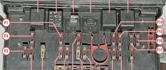
Description of the main unit with fuses and relays
The main location of the block is to the left of the steering column . The device is closed from below with a special lid. You only need to unscrew two screws to get to the internal contents. After this, squeeze out the upper edge of the lid, gradually freeing this part from all fasteners. The entire connection diagram for the VAZ 2123 speed sensor and other devices becomes available.
A block will appear, which is held on a special bracket. Depending on the configuration and year of manufacture, the circuit itself varies, as does the total number of fuses.
Comments and reviews
In the event of any malfunction, this hint becomes necessary, and therefore the issue of the relevance of the location and purpose of this diagram is indisputable, so in this article we will consider all the details separately, where they are located and what their functions are.
All available connections operate thanks to an electrical circuit diagram that consumes electrical energy. The rest of the work is not regulated, and the entire device is changed. The ignition key closes almost all circuits. Which is better Bosch or January? PTFs are not included in the standard package and are an additional option.
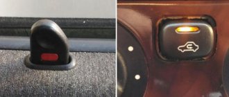
Heater motor switch. The switch is in the driver's door pillar.
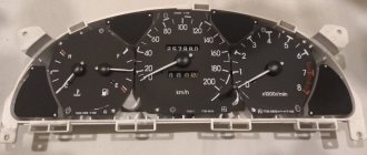
The Chevrolet Niva dashboard controls the operation of functionally important systems. Almost all circuits, except for the charging and engine starting circuit, are protected by fuses.
Search form
The role of the current source is played by the battery. They can be powered in parallel from the circuits described or have their own fuse. It combines a speedometer, tachometer, thermometer, and fuel level indicator.
Door lock system control unit. It is when carrying out repair work on the electrical components of a Chevrolet Niva SUV that the electrical circuit serves as an indispensable assistant. Contents 2 Diagram in pictures Why is it needed? It helps to understand where and what device is located, and what functions it performs; it displays all the devices, circuits and elements, etc.
Almost all circuits, except for the charging and engine starting circuit, are protected by fuses. Switching operating modes is carried out by control levers on the steering column of the car. The wiring diagram can be divided into two blocks: Sources; Electrical equipment of Chevrolet Niva. Thanks to the built-in filter and rectifier, you can get a constant voltage at the output, varying from 13.2 to 14.7 V. Therefore, if you decide to troubleshoot an electronic circuit, then this instruction will serve as an indispensable assistant for you . Additional starter relay for Niva Chevrolet, solution to the problem of starting the engine when hot
Relay and fuse locations
The main part of the fuses is located inside the cabin, under the panel to the left of the steering column. In total there are four blocks :
- Engine control system fuses.
- Windshield wiper.
- General fuses.
- The engine management system, which is always complemented by the Chevy Niva circuit.
The last block is located at the bottom.
The main and additional blocks are always connected to each other . 10 fuses are included in the top block. There are six of them in the lower one. Cooling works, among other things, due to such a device.
The relay box for the engine management system is located below the main, additional fuse box. There are a total of five relays and one fuse in this part. Sometimes the so-called starter relay is additionally included in the circuit; the year of manufacture becomes the determining factor.
There are also mounting blocks , which are also located to the right or left of the steering column.
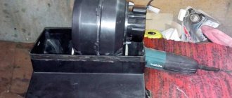
Modernization of the heating device in a Chevrolet Niva car
Before the heater is improved, it is necessary to understand the principle of operation of the dampers. Then you should completely dismantle the decorative panels located on the left side of the Chevrolet Niva stove. The next step is to remove the regulator responsible for the position of the dampers. When optimizing your car, you need to understand the design of the heating device, which will allow you to dismantle the “unnecessary” equipment without unnecessary delays. The motorist must remove the lower part of the regulator, through which the front flap is activated.
And also interesting: Tuning the interior of a VAZ 2121 - improving the Niva with your own hands Video
When dismantling all the plastic elements, you should not try to abruptly remove the parts, since almost all the components of the device being disassembled are made of fragile plastic, which breaks even under more or less significant impact. If, however, due to haste or carelessness of the owner of the movable property, the lower part of the device being removed gets a crack, it can be hidden with a soldering iron.
Modifying the Chevrolet Niva stove with your own hands involves the need to secure the lower damper so that it is tightly closed in the upper position. Of course, such a modernization completely eliminates the ability of the motorist to take advantage of the “front” position, however, it provides many other more significant advantages.
To tightly fix the front flap, you will have to make a small-sized bracket with your own hands (it is best to resort to using a simple tin), which will be held on by a self-tapping screw.
Once the “front” of the stove is in the closed position, you will need to think through the trajectory of the element that regulates the simultaneous supply of heat to the glass and legs. It is worth noting that skilled craftsmen, when upgrading their Chevrolet Niva, use all available means, in particular, an ordinary discount card will be useful for optimizing the stove. By means of which a cut line is drawn, then the element is glued with cyanoacrylate and filed to size with a file.
The modification of the Chevrolet Niva heater should be completed after the hand-cut part is glued with superglue.
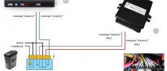
Additional relay and fuse box
Additional fuse circuits usually include the following elements:
- electric lifts for front doors;
- electric climate control fan and air conditioning compressor;
- heaters at the side mirrors. The back element is missing;
- interior lamp;
- air conditioning fan, air conditioning compressor.
Wiring diagram Chevrolet Niva VAZ-2123
Electrical connection diagram of the ECM AZ-2123
1 – controller; 2 – electric fan of the engine cooling system, right; 3 – electric fan of the engine cooling system, left; 4 – ignition module; 5 – spark plugs; 6 – nozzles; 7 – resistor; 8 – block of the ignition system harness to the injector harness; 9 – block of the injector harness to the ignition system harness; 10 – oil pressure warning lamp sensor; 11 – mass air flow sensor; 12 – coolant temperature sensor; 13 – throttle position sensor; 14 – idle speed regulator; 15 – oxygen sensor; 16 – crankshaft position sensor; 17 – knock sensor; 18 – solenoid valve for purge of the adsorber; 19 – coolant temperature indicator sensor; 20 – additional relay; 21 – right electric fan relay; 22 – fuse for the power supply circuit of the right electric fan; 23 – left electric fan relay; 24 – fuse for the power supply circuit of the left electric fan; 25 – electric fuel pump relay; 26 – fuse for the electric fuel pump power supply circuit; 27 – ignition relay fuse; 28 – ignition relay; 29 – controller power supply fuse; 30 – block of the ignition system harness to the instrument panel harness; 31 – instrument panel harness connector to the ignition system harness; 32 – ignition switch; 33 – automobile anti-theft system; 34 – vehicle speed sensor; 35 – electric fuel pump; 36 – instrument cluster; 37 – mounting block; 38 – diagnostic block; 39 – control lamp block; 40 – instrument panel harness block to the rear harness; 41 – rear harness block to instrument panel harness; A - to the negative terminal of the battery; B - to the “plus” terminal of the battery; C1, C2 – grounding points of the ignition system harness; C3 – grounding point of the instrument panel harness; C4 is the grounding point for the rear harness.
The wires in this diagram have a letter designation of color and a designation of the number of the circuit element to which this wire is connected.
The number of the block contact is indicated through the fraction.
The symbol "S28" or "SB" means that the wire is connected to the circuit element numbered 28 or designated by the letter B through a connection point not shown in the diagram
Electrical diagram of VAZ-2123
1 – right headlight; 2 – sound signal; 3 – engine compartment lamp; 4 – engine compartment lamp switch; 5 – starter; 6 – battery; 7 – generator; 8 – air temperature sensor; 9 – left headlight; 10 – power window switch for the right front door (passenger); 11 – gear motors for electric windows; 12 – switches in the door pillars; 13 – gearmotors for blocking door locks; 14 – connection block to the right front column; 15 – heater electric motor; 16 – speed sensor; 17 – windshield washer electric motor; 18 – electric motor for windshield wiper; 19 – switch in the driver’s door pillar; 20 – driver’s door locking motor; 21 – brake fluid level sensor; 22 – connection block to the left front column; 23 – power window switch for the right front door (driver); 24 – left front door power window switch; 25 – mounting block; 26 – relay for turning on electric windows; 27 – relay for turning on the sound signal; 28 – diagnostic block; 29 – control unit for the door lock system; 30 – connection block to the wiring harness of the front seat heating system; 31 – connection block to the injection system wiring harness; 32 – instrument cluster; 33 – right side turn signal; 34 – glove box lighting lamp; 35 – switch for the glove compartment lighting lamp; 36 – ignition switch; 37 – brake light switch; 38 – reverse lamp switch; 39 – control lamp block; 40 – headlight leveling regulator; 41 – instrument lighting regulator; 42 – steering column switch; 43 – left side direction indicator; 44 – heater motor switch; 45 – additional resistor; 46 – handbrake sensor; 47 – switch for rear fog lights; 48 – fog lamp switch; 49 – rear window heating switch; 50 – external lighting switch; 51 – alarm switch; 52 – connection block to the right rear column; 53 – electric fuel pump with fuel level sensor; 54 – backlight lamps for heater control levers; 55 – differential engagement sensor; 56 – cigarette lighter; 57 – backlight lamp; 58 – control unit of the automobile anti-theft system; 59 – interior lamp; 60 – canopy for individual interior lighting; 61 – connection block to the radio device; 62 – connection block to the left rear column; 63 – right rear light; 64 – trunk lighting; 65 – license plate lights; 66 – rear window washer electric motor; 67 – electric motor for rear window wiper; 68 – rear window heating element; 69 – additional brake signal; 70 – left rear light.
Connection between battery and starter
Each car has its own starter installation scheme. There may be several access options :
- on right;
- left;
- from the radiator side;
- from the salon side.
It is often necessary to use a lift or inspection pit to reach this component. The mechanism is needed to ensure engagement between the gear and the flywheel. Therefore, the device is most often located in the area where the clutch housing is attached. The electronic version is no exception.
For connection, only one connector is used , to which a special terminal is added. The starter starts working every time the owner turns the key.
It is best to use a multimeter to detect breakdowns in one of these parts of the car. But faults can be easily determined using other simple manipulations.
In most cases, repairing the starter is possible, even if such an important part as the windings has failed . The electrical equipment of a car in most areas is subject to complete restoration.