Standard Chevrolet Niva fuses are designed to protect the vehicle's electronic equipment. The unit is located in a place rare for modern cars - inside the cabin. There is a safety module installed under the glove box. The box is responsible for the secondary circuits of the equipment and is not directly related to the power plant.
The main engine relay is mounted as a separate unit. On Chevrolet Niva 2017-2019 it is in the form of a plastic cube.
Where are the fuse box and relays of the Niva Chevrolet
The location of the inserts on cars has not changed from 2011 to 2021.
To gain access to the main unit, you should pick the instrument panel in the area of the pedal assembly. Under the dashboard, to the left of the steering wheel. To get to the panel under the tidy, use a Phillips screwdriver to remove the plastic casing, where the panel will be.
The next part is located under the glove compartment. To get to the site you will need to completely dismantle the glove box. The installation location was not chosen by chance. The module cover is protected from mechanical damage and moisture, and breakdowns inside are rare. Repair is not difficult.
In the pre-Restyle version, the main unit was located in the engine compartment and the inserts were located under the hood near the ECU, where the main electronic element of the car was installed.
A detailed location with a description is in the photo below.
Chevrolet Niva fuses with description
The main elements of a car can be divided into two groups based on location. Consequently, their purpose will be different.
The photo shows a fuse panel, relevant for models manufactured after 2009.
For convenience, it is better to present the decoding in the form of a table.
| Number | Circuit Description |
| F1 | License plate lighting, side lights on the left side of the car. |
| F2-4 | The main lighting is low beam, high beam and fog lamps on the left side of the car. In some configurations, fuse No. 4 is a spare socket. |
| F5 | Main power window protection relay |
| F6 | Cigarette lighter power supply. Some motorists connect power cores here instead of an incandescent filament. |
| F7 | Horn connection relay. |
| F8 | Heated rear glass and rear view mirrors. |
| F9 | Interior lighting switch, glove compartment lighting, wiper drive and electrics. Separate outlet for windshield washer system compressor. |
| F10 | Standard control module for electrical accessories and door locking, or spare |
| F11-14 | Exterior car lighting. Low and high beam head optics, fog lights, side lights. The fuses are responsible for the right side of the vehicle. |
| F15 | Standard control system for rear view mirror drives. Fuse for heated seats. The minimum configuration does not include the insert. |
| F16 | Hazard warning light breakers and turn relays |
| F17 | Interior lighting, partial display of the instrument panel, alarm position control, brake signals, additional stop block. |
| F18 | Power heating fan |
| F19 | Starter head relay, instrument panel lighting and indication, turn signal relay system in turn mode. |
| F20 | Rear fog lamps, immobilizer and anti-theft alarm buzzer. |
The car radio and speedometer are connected separately from the main fuses. The drives of the injectors and air conditioning compressor are designed similarly. Depending on the configuration and year of manufacture, the listed components may be connected according to a different scheme.
Also in the VAZ 2123 panel there are spare fuses located in separate sockets.
Additional fuse block
The DBP, also known as the engine control panel, is located under the dashboard at the passenger's feet.
To gain access to the unit, you will need to dismantle the glove box. Below it is an auxiliary module. Here the main part is represented by relays, but there are also fuses. Fuse links have markings and areas of responsibility:
- No. 2 – high-power fuse responsible for protecting the power lines of the electrical circuit of the right radiator fan and an additional relay group;
- No. 3 – safety insert for the fuel pump located in the tank;
- No. 4 – the element is responsible for powering the car controller circuit;
- No. 9 – fuse for the right radiator fan;
- No. 10 – insert protecting power lines and circuits switched on by the main relay.
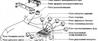
Relay Niva Chevrolet
Two places where protective inserts of electrical circuits are concentrated are presented. The explanation of the automatic circuit switching nodes is as follows.
Main mounting block.
| Designation in the diagram | Decoding of the serviced circuit and equipment |
| K1 | Mostly not used, but in some configurations it can be connected. |
| K2 | Window cleaning system, relay powers electric motor. |
| K3 | Turn signal breaker in working position |
| K4 | Headlight module - low beam switching on |
| K5 | Protective switch for turning on and powering the high beam head optics |
| K6 | An additional relay is responsible for the operation of several nodes simultaneously. Typically, the heated glass of the aft part, the fan drive of the heating system, and the windshield and rear window washers are connected here. |
| K7 | In some configurations it acts as a fuse for the heating element of the cargo compartment door. |
| K8 | Not used |
The car’s design also includes a remote control panel:
- K1/2 – standard fog lights (if equipped);
- K3 – activation of the seat heating system;
- K4 – horn protection;
- K5 – standard inclusion of the starter circuit.
Separately, you should consider the engine control system unit:
- K1 – additional relay;
- K5-6 – head radiator fan inserts for the left and right sides, respectively;
- K7 – power supply to the fuel pump circuit;
- K8 is the main relay of the car.
For cars after restyling
- Car manuals, instructions, repair and operation manuals for cars 24 views
- BMW error codes 22 views
- Mercedes error codes 19 views
- Ford car repair and operation manual 15 views
- Fuse and relay box Nissan Primera P12 from 2002 to 2007 14 views
- Repair and operation manual for VW cars 13 views
- Fuse and relay box in Opel Vectra B from 1995 - 2000 12 views
- Honda self-diagnosis 11 views
- Location of diagnostic OBD connector for Citroen 11 views
- BMW car repair and operation manual 11 views
Restyling forced the introduction of units of a new configuration, marked with the number 2123-3722010.
In total, about five fuses and five relays are placed in the connectors of the block. Also here you can find a protective insert for the 15A fuel pump. The part has a separate relay installed to control the fuel supply.
A typical fuel pump relay 75.3777-10 has 4 contacts, a coil with an armature, and a spring for opening the contact. When voltage is applied to the control contacts, the rod is drawn into the winding and another pair of contacts is closed. It turns off automatically as soon as the low-current connectors are de-energized.
Advantages of using relays in Niva Chevrolet cars:
- spontaneous leakage current in the on-board system is eliminated;
- reliable control of all electric motors;
- quick and guaranteed start of electrical mechanisms;
- Network overload protection.
The fuel pump relay has appeared on cars of the Chevrolet Niva family since 2003, when an injection engine was installed. The engines of the VAZ 21213 family are equipped with a carburetor and do not have a relay in the fuel supply system.
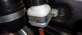
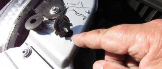
The Chevrolet Niva compares favorably with its predecessor primarily in its layout and convenient access to all parts. The designers have provided the most reliable place for the relay and fuse box in this SUV - in the cabin under the dashboard. In total, 2 mounting blocks are installed in Niva Chevrolet. The first is located to the left of the steering column under the hinged lid, the second under the glove compartment on the front passenger side.
We are interested in the second block. It combines the engine control unit and 4 power relays on a metal strip. From the outside, this unit is covered with a decorative plastic cover. The device we are interested in is located third on the left. The Chevy Niva fuel pump fuse is located on the left edge of this block. The fuse rating is 15 A. For easy access to it, it is recommended to remove the glove box cover.
The procedure for disassembling the glove compartment of a Chevy Niva:
- remove the terminal from the battery;
- use a screwdriver to unscrew the screws securing the glove compartment (1 on the right, 2 on the left and a pair in the upper and lower parts);
- tilt the glove compartment body forward and carefully pull it out, disconnect the backlight;
- remove the protective cover of the mounting block.
The exact location is shown in the photo. You can clearly see the factory markings of each connector and what it is responsible for. Changes in the restyled car since 2009 from the pre-restyling car affected only the main mounting block with relays and fuses. Now several electrical circuits are connected to one relay. The location of the relays and fuses under the glove compartment has not changed.
When the engine is started, during the ignition operation, power is supplied to all the windings that are located in the starter. These windings come in two types: retracting and holding. The starter is connected to the retractor winding, and the entire housing control circuit begins to work thanks to the holding winding.
When current flows to the terminals, magnetic induction occurs, which creates a magnetic field. Thus, the armature presses on the return spring, and the bendix rotates. When the engine starts running, the power is turned off and the armature returns to its original position as the spring returns it.
The contacts are disconnected.
If the starter relay works well, then the power is at 8 V and the temperature does not exceed 25 ° C. In the case when the power is above this mark, then you need to look for faults in the starter and its relay.
Despite the fact that at first glance these systems only affect the comfort of the driver and passengers during the trip, it turns out that they are closely connected with the defrosting system and remove steam from it. If the system malfunctions, driving the Niva in conditions of limited visibility will significantly increase the danger of movement.
Read news about the new Niva
- The modernized Lada Niva Legend (4x4) 2021 was shown on the Internet
- Lada 4×4 Bronto - sales stopped, new details » Lada.Online - all the most interesting and useful about LADA cars
- Description of the instrument panel Lada 4×4 (VAZ 2121, 2131) » Lada.Online - all the most interesting and useful about LADA cars
- LADA Niva – Operating manual – Official LADA website
- Chevrolet Niva gasoline consumption per 100 km
- Buy LADA (VAZ) 2131 (4×4) 2021 in Rostov-on-Don, low price for Lada 2131 (4×4) 2021 on the Avto.ru website
- Fuses Niva 21214 injector «
- The new large Lada 4×4 Niva “Bigster” 2021-2022 based on the Dacia Bigster was shown for the first time. The SUV has changed beyond recognition
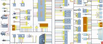
Schnivy fuse and relay diagram
The electrical circuit is not particularly complex or confusing. The abundance of simple equipment, mainly without feedback, does not overload the electrical circuit.
A separate element is the electrical package unit numbered 1118 6512010. The part is installed optionally and exclusively in certain configurations. Cars equipped with electrical accessories have a complicated circuit. The electrical circuit of the car has terminals for a trailer, a portable socket, and a towbar terminal connection. All network elements and nodes are powered through the instrument cluster, which makes troubleshooting easier.
Cigarette lighter fuse Niva Chevrolet
Due to the “excellent stability” of the domestic manufacturer, replacing the cigarette lighter fuse on a car always presents more problems than on similar imported cars.
The main problem is the constant transfer of the fuse link to different places. Consequently, when a part burns out, its replacement is accompanied by a search for the required joint throughout the machine. The photo shows the required fuse in the 2010 car modification.
For machine versions 2006, 2007, 2014 and 2021, the location of the element may differ.
The guard often fails; some drivers change the electrical circuit of the car for the sake of operating comfort. Users power the cell directly from the battery and insert a powerful fuse into the circuit. This manipulation makes it easier to repair the unit and makes it possible to strengthen the structure for connecting energy-intensive devices such as charging for a laptop, vacuum cleaner or fan.
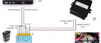
Window control unit
On models 2009 and 2013 (after restyling), the electrical circuit looks like this.
Here the pinout of the devices is as follows.
- 1 – fuse mounting block;
- 2 – window regulator activation relay;
- 3/6 – electric drive switches for the front left and right doors, respectively;
- 4/5 – directly the gear motor for the left and right mechanisms, respectively.
If the fuse responsible for the device is constantly on, the problem may be hidden in a shorted motor or control button. The device should be tested and damaged elements replaced.
The device is not supplied in separate configurations by the factory. But you can easily install it yourself. The price of the head module of the power window control system starts from 800 rubles. The average price tag on the market is 1000-1200.
Where is the Niva Chevrolet alarm unit located?
The car is delivered to the market equipped with a standard anti-theft system. There is a door lock and an immobilizer, and it is also possible to sound a sound signal. All elements of the chain are securely hidden from prying eyes.
Two-way communication provides the driver with a response when trying to open or steal a car. If intruders try to steal a car, the corresponding indicator on the key fob will light up and a beep will sound.
The disadvantages of factory anti-theft systems are typical problems for the domestic automobile industry - low reliability of modules and frequent failures. Some car enthusiasts complain that the brake light does not work or the emergency lights do not turn on (when they try to break into the car, the car does not show signs of life).
To solve the problem, car enthusiasts install another alarm and connect it to the standard connector. To perform this operation, disconnect the factory box located under the fuse mounting block.
Shnivy stove control unit
It is a closed panel with remote controls and keys.
At the same time, the design of the device from 2004 and the version after the 2012-2016 restyling has not changed. There is a fan rotation control at 4 speeds and heating intensity control. There is also a knob for distributing air flow into individual zones. In some cases, the user needs to repair the module, which means removing and replacing it, or modifying it. Usually the cause of a breakdown is a burnt-out resistor or broken rods.
To remove the heater control panel you will need to perform a number of steps.
- The first step is to disconnect the terminal from the battery.
- Next, we go into the interior and, holding the fan position regulator, you need to pull it towards you until the last one comes out of the groove.
- Then disconnect the other adjustments in the same way and disconnect the rod lever.
- Next, armed with a flat-head screwdriver or similar object, you need to pry off the plastic clips of the device cover.
- After snapping the clips, the panel will disengage and can be removed in the same way as the handles.
- The last stage is to disconnect the wiring joints.
- Assembling the air heating system is carried out in the reverse order.
You can see in detail how to dismantle the stove drive in the video.
Turning relays and fuses
In the standard diagram it is presented under No. 16 of the main mounting block. It looks like a standard fuse link. On cars up to and including 2008, the emergency light fuse was located separately, but a new circuit installed by car enthusiasts corrected the situation.
The system also has a protective relay-breaker. The element is located in the main mounting block under number K3. When the switch burns out or fails, the lights begin to blink faster than usual or stay on constantly. The location of the relay has been chosen well - replacing it is not difficult even in a garage.
The main malfunctions of the system arise precisely in these elements, but there are also breakdowns of the steering column switch.
Relay and fuse for size Niva Chevrolet
In the system of cars after 2008, insertion F1 of the main mounting block is responsible for the operation. The right side is powered through fuse F14.
Elements often fail due to moisture getting on the contact group of the lamps and their damage - the placement of optical devices affects it.
Ignition unit
The main module is a separate block.
The device is located on the engine and is secured with screws. The part has a simple purpose - adjusting the timing of the spark depending on the general condition of the motor. When the circuit begins to fail, it must be completely replaced - the panel cannot be repaired.
There is no part on carburetor cars produced in 2005. The following information is valid for the newer version.
The unit is disconnected after disconnecting the battery using head No. 10. Before manipulation, it is recommended to disconnect the high-voltage conductors and the contact group of the ECU. Installation is performed in reverse order.
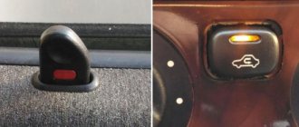
Chevrolet Niva warning lamp unit: description
After the 2015 release, there is an updated module that indicates the status of the vehicle systems in real time. The lamps are located next to the buttons or placed separately on the dashboard.
There are a total of 7 indicators on the standard diagram.
- The center differential lock activation icon lights up only when the mechanism is activated.
- Used for standard immobilizer.
- Indicates a leak in the power steering system.
- A simple designation is the activation of the ABS complex. It may also indicate a puncture of one or more wheels.
- Triggering of the SRS system.
- The requirement to check the engine, or can act as an indicator of the level of brake fluid in the reservoir.
- Lights up when seat belts are not fastened.
Niva Chevrolet: reverse sensor
The electronic part is mounted on the rear of the gearbox housing and is responsible for the operation of the reverse lights. Periodically, the device fails and the system produces incorrect data. This is caused by unfavorable placement of the device on the machine. The part is constantly exposed to dirt, dust and obstacles on the road can interfere.
Replacing the sensor is simple. To perform the operation, just follow the procedure:
- pull off the sensor power terminal;
- unscrew the sensor from its seat;
- Install the new one in reverse order.
Chevrolet Niva central locking unit
It is an electronic module that connects door lock drives. The part often fails due to a blown fuse or a short circuit in the door wiring.
The photo shows the standard central locking pinout for the most common versions of the car.
- directly the mounting block.
- BOO.
- Reducers for blocking aft passenger doors.
- Same for the front passenger door.
- Accordingly, the driver's part with the corresponding conclusion.
Comfort block
Another name is the electrical package control unit. The module is in the form of a plastic box with circuits located in it. On the lower part there are contact groups for connecting window regulators and regulators.
The device is modular and cannot be repaired if it breaks down. Regardless of the version and configuration of the machine, it is located behind the main fuse mounting block.
Shnivy headlight block
The modern modification of the new model is equipped with a modular lighting unit.
The part is responsible for supplying high and low beams. There is also a daytime running light or DRL lamp. It is noteworthy that there is no connector for fog lights. The headlight is simply not designed for the installation of additional elements. Installation of fog lights is carried out separately.
The autolight device is simple. There is a contact group of wires, lamps, a reflector and everything is like a standard modern device. Thanks to the modernization of optics and the installation of efficient light bulbs, the PTF system is not needed to provide normal lighting.
Charging relays and fuses
Users access the nodes when the battery is not charging. Depending on the age of the car, the battery protection is installed on the right fender liner near the battery or generator. Also, due to the “whims” of the manufacturer, the part can be located anywhere. Searches are usually carried out in the wiring section between the battery and the generator.
If the problem is in the relay, it should be changed completely. The node cannot be restored.
Shnivy immobilizer unit
The standard immobilizer on the Niva is part of the security system and is responsible for blocking the engine during an attempt to steal it.
The specified car is supplied to the market with the standard APS-6 model. Modification in the form of a simple design with increased reliability. The unit is housed in a metal case, which helps protect it from mechanical damage and shock. The protective module is mounted under the plastic cover of the center console. It is easy to recognize - contacts coming out from the installation are connected to the engine control system, which allows you to block its operation and starting.
Chevrolet Niva wiper fuses and relays
In the standard unit, insert F9 is responsible for the operation of the windshield wiper. You can change it with special tweezers. The wiper relay number K2 is a more complex unit. The design with adjustable response time allows you to maintain pauses between flashing bulbs.
The breaker is located in the mounting block. If the insert is damaged or faulty, replace it. The part is not repairable.
Chevrolet Niva mirror control unit
Most old-style machines in use do not have such an option. In new versions, the unit is installed from the factory and is a convenient addition.
The module is powered by fuse No. 5 and relay index K4. If the mirror adjustment does not work or responds intermittently, they should be checked.
The heating and adjustment system is activated only when the ignition is turned on. When trying to adjust the mirrors without a key, nothing happens - this is normal.
Fuses and relays for windshield wipers
Inserts F9 and K2 are responsible for the operation of the windshield washer. They also prevent the rear window sprayer pump, if equipped, from overloading.
There are no special features in the design. The parts are included in the circuit after the switch and can be easily replaced with new ones.
Chevy Niva window control unit
Located on the center console in the armrest area. Some modifications are equipped with a regulator mounted in the door niche.
A common problem is system failure. If the lift is burnt out, it should also be replaced entirely.
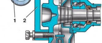
Solenoid relay
Similar to all other models, it is located on the body of the part and is responsible for the clutch of the flywheel with the “starter”. A typical breakdown is when, when trying to start the engine, there are no characteristic clicks similar to the clatter of fingers.
To replace, you will need to remove the starter from the car and disassemble it. Also, some experts recommend simultaneously inspecting the starter.
Front axle disconnect unit
The front-wheel drive deactivation system is of particular interest. Mechanical structure device, mounted separately. The part is not installed from the factory - the car only has all-wheel drive.
Due to the design features of the Shniva, before finding out the article number for ordering, you should study the box model. On different modifications, the seats may differ slightly, which will lead to oil leaks from the gearbox.
A similar system on the Internet has controversial reviews. Some users claim that fuel consumption decreases and top speed increases. Opponents of the modification speak out about increasing the load on the rear axle.
Climate control unit
The module is installed on cars exclusively in the Luxury configuration. The device is not available to most owners.
The unit is directly connected to the cooling system and regulates the distribution, temperature and intensity of air flow into the cabin.
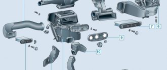
Injection system relay and fuse box
The part is located directly on the power plant and is part of the ECM. If the device fails, the engine may stutter, sneeze, lose dynamics, or the engine refuses to start.
Diagnosis of the problem is carried out by the scanner through the appropriate connector. After finding the problem, it is recommended to replace the entire assembly.
Power sensor
If various elements in the car do not work, then first of all we begin to look for the fuse that is responsible for this device. This can be easily done if you rely on the information provided above, and take it out of its seat; this can be done with tweezers.
After removal, we carry out a visual inspection of the appearance; if there are no external defects, then we resort to using a tester, switch it to the prozvana mode, and the probes should be placed on the ends of the fuse. If the element is faulty there will be silence, if it is normal, the tester will start making sounds. Once a faulty fuse is found, it should be replaced with a new one designed for the required current value. As you can see, the procedure for detecting and replacing burnt-out elements is not a complicated procedure, and you can do it yourself.
There are two types of car blocks - for those produced before and after 2009. Unfortunately, parts from cars before and after restyling are not interchangeable. But the blocks located behind the glove box have virtually no structural differences. that is why when replacing them, the year of manufacture of the car will not matter.
The protective device may fail due to long periods of use, so if any consumer stops working, the first thing to check is its fuse.
They are held in their nests by sliding contacts. In order to remove the element, simply pull it out of the socket. To make this more convenient, modern mounting blocks are equipped with plastic tweezers.
A faulty fuse can be determined by visual inspection or using an ohmmeter. Since the housings are made of transparent plastic, the integrity of the conductor is easy to determine with the naked eye. In addition, conductor burnout is accompanied by an increase in temperature. Traces of heat exposure remain on the plastic case. Having selected an element suitable for its nominal value, it is inserted into the socket in place of the failed one.
If a fuse burns out on the road, you can replace it with an identical one that protects the circuit of the consumer that is not currently in use.
More information about Chevrolet Niva electronics can be found here.
The ignition relay is located in the passenger compartment fuse box; it can be found on the driver's side of the instrument panel, opposite the seat. On the diagram it is usually designated K6 and in the technical description it is sometimes called an addition relay.
It is responsible for turning on the fuel pump and supplying voltage to other elements. Triggered when the ignition key is turned. At this moment, you can hear a click behind the instrument panel. This electric coil built into the relay receives voltage and closes the contacts of a certain circuit. If there is no characteristic sound when turning the key, this may indicate its failure.
This element is marked K3 in the diagram. It is responsible not only for the turn lamps, but is also activated when the hazard lights are turned on. It has a slightly different structure, unlike K4 and K5, since it has a built-in timer that turns on and off the circuit at a given interval. Thanks to this, it ensures that the lamps flicker.
But if everything is in order with the relay, and the devices do not work, then there may be a problem elsewhere - the mass attachment point. The negative wire coming out of the battery is connected to the car body and goes to some of the main energy consumers in the form of wires. This is sometimes the difficulty when calling an electrician.
The architecture of the circuit can be described as follows: a wiring harness comes out of the negative terminal, connecting devices operating from one ground point, then wires connecting other ground points are connected to them using a crimp sleeve. As a result, finding a specific mass attachment point is quite difficult.
For example, the mass of the mirror control unit is located behind the trunk trim. But with the engine everything is a little simpler. Since it is connected to the frame and body through pads, which are essentially a dielectric, it has its own wiring harness. The terminals are located on the left side of the engine, below the ignition module. They are responsible for the operation of the ECU and ECM sensors.
If, after checking all of the above, you find the reason why the radiator fan does not turn on, you only have to check one wire - the radiator sensor wire. To do this, you must remove the switch as it does not allow access to the fuse box plugs. This means we remove the plug from the fuse block and check the radiator sensor wire for a break.
We check as follows: connect the wire to the “ ” terminal of the battery, install the second end into the connector of the chip. Next, remove the plug from the sensor and connect the light bulb. If there is no light bulb, make a “teal” to ground. If there is no voltage, most likely this wire is broken.
If the fan does not turn on, the reason may be completely unexpected, for example, a burnt gasket under the head. Switching on does not occur for the reason that the coolant does not enter the cylinder, while gases from the cylinder penetrate into the coolant, creating an effect known as an air lock.
WHAT TO DO IF THE RADIATOR COOLING FAN DOES NOT WORK
Problems with the electric motor. If the electric motor fails, its rotor will not spin, and accordingly, the impeller will not rotate. You can check the performance of the electric motor by connecting it directly to the battery. To do this, you will need to take two wires, connect them to two battery terminals and two electric motor terminals.
If the fan does not spin when connected directly to the battery, we can conclude that the electric motor needs to be replaced; Problems with the sensor. If the sensor is unable to detect the coolant temperature and transmit a signal to turn on the electric motor, it will need to be replaced. To make sure that it is not working, you need to disconnect two wires from it and short them together.
If the electric motor starts to spin the impeller, this will indicate that the sensor is faulty and needs to be replaced; There is no tension. The third and most common reason for a non-working radiator cooling fan is the lack of voltage in its power supply circuit. If there is a break in the wires or a fuse fails, the circuit will be de-energized.
RADIATOR COOLING FAN IS NOT WORKING: HOW TO USE THE CAR
Also interesting: Generator Niva 2121, 21213, 21214: which one is installed, replacement
Try turning on forced operation of the fan from the battery; If the fan is not forced, you should drive at a constant speed of about 60 kilometers per hour or higher so that the oncoming air flow cools the fluid on the radiator without the help of a fan. It is also recommended to turn on the heating system in the car interior so that some of the heat from the coolant escapes into the cabin.
Technical parameters of Chevrolet Niva (2123) 1.7 / Chevrolet Niva (2123) in a 5-door body. SUV with an 80 hp engine, 5 manual transmission, produced from 2002 to 2009.
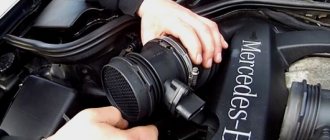
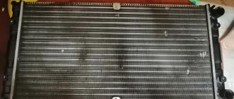
The designers of the Chevrolet Niva used a dual fan unit in the cooling system. This slightly complicated the connection diagram, but sharply increased the efficiency of radiator airflow. The fans are driven by 12-volt DC synchronous motors with a permanent magnet inductor. Electric motors have a closed, non-demountable design and do not require maintenance.
The power of each electric motor is 110 W. The fan assembly draws 18 amps.
The fans are turned on one by one using an electromagnetic relay controlled by the on-board computer. When the coolant heats up above 99 degrees, the electric fan located closer to the engine air intake starts. The switch-on temperature of the second impeller is 101 degrees. The fan connection diagram is shown below.
- Voltage is applied to the control terminals.
- Current passes through the inductor, resulting in an electromagnetic field.
- The steel contacts attract and close.
- The current passing through the relay drives the electric motor.
- Disconnect all wires
- Removing the upper pipe
- Removing the bumper
- If there is an air conditioner, bend the tubes (this must be done carefully, as they may burst) or drain the freon (filling it back will not be cheap), then remove the air conditioner radiator.
- You need to loosen the nuts on the radiator casing
- Tilt the radiator so that you can remove the fan unit
- Unscrew the bolts that secure the block and remove it
Reasons for failure of shnivy fuses
Inserts burn out due to the following reasons:
- short circuit in the serviced circuit;
- sudden voltage surge;
- wiring damage;
- violation of cable insulation;
- installation of too powerful equipment.
Due to the failure of the fuses, the engine may not start, and the serviced unit completely breaks down.
A burnt out relay behaves similarly. The insert does not click when tested, the powered circuit is completely de-energized.