Location of the main components of the car
The power unit is located in the engine compartment under the hood; it occupies most of the engine compartment.
The power unit is the engine along with the clutch, gearbox (clutch and gearbox are elements of the transmission) and the starter and generator installed on the engine. The engine includes systems that enable it to operate. These include lubrication, cooling, power and exhaust systems. The operation of the injection engine is controlled by the ECM (electronic engine management system). In addition, the car has an engine starting system (starter, electrical circuits and switching devices) and a power supply system (generator and battery). The last two systems belong to the group of electrical equipment elements.
Engine compartment of a VAZ-2109 car with a carburetor engine
1 – windshield washer reservoir and tailgate glass; 2 – upper support of the rack; 3 – air filter housing; 4 – brake system hydraulic reservoir; 5 – expansion tank of the cooling system; 6 – battery; 7 – gearbox (not visible); 8 – engine.
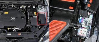
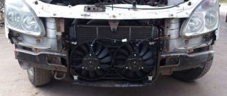
Engine compartment of a VAZ-21099 car with an injection engine
1 – windshield washer reservoir; 2 – upper support of the rack; 3 – receiver; 4 – brake system hydraulic reservoir; 5 – expansion tank of the cooling system; 6 – battery; 7 – air filter housing; 8 – gearbox; 9 – engine.
VAZ 21099
The idea of creating a sedan based on the 2108/2109 models haunted the creators from the very moment they were launched into series. The fact is that in the USSR, even in the 80s, a car was still a luxury and the buyer preferred modern Samaras to the time-tested “classics”, which had a more spacious trunk and a comfortable interior.
In this regard, VAZ management constantly received letters from Soviet car enthusiasts demanding the release of a new sedan. In Togliatti they listened to these requirements and in 1990 launched the Lada 21099 into mass production.
Bottom view
The front of the car. The levers, braces and anti-roll bar of the front suspension are clearly visible (like the front wheels, they belong to the group of chassis elements).
1 – front wheel suspension arm (chassis); 2 – lever extension (chassis); 3 – engine (sump pan with oil drain plug); 4 – gearbox; 5 – front wheel drive shaft (front wheel drives belong to the transmission); 6 – anti-roll bar (chassis); 7 – exhaust system (exhaust system).
The back of the car's underbody.
The beam is clearly visible, the shock absorbers and springs of the rear suspension are partially visible.
The main muffler of the exhaust system is located next to the wheel. At the rear of the car, behind the rear suspension beam, you can see a niche in the bottom of the trunk, which houses the spare wheel. 1 – shock absorber; 2 – rear suspension beam (chassis); 3 – fuel filter of the power supply system (only a car with an injection engine); 4 – main muffler of the exhaust gas system; 5 – niche in the bottom of the trunk for a spare wheel.
The bottom of the car under the driver and front passenger seats.
Under the bottom, parallel to the additional muffler pipe, there is a transmission control drive rod.
1 – additional exhaust system muffler; 2 – pipelines for hydraulic drive of the brake system and engine power supply system; 3 – drive rod for controlling the gearbox (transmission).
The bottom of the car under the seats of the rear passengers. The fuel tank is located under the bottom, in front of the rear suspension beam. Near the fuel tank, there is a pressure regulator that adjusts the brake fluid pressure in the brake mechanisms of the rear wheels. The pressure regulator belongs to the brake system.
1 – additional exhaust system muffler; 2 – fluid pressure regulator in the brake mechanisms of the rear wheels; 3 – fuel tank.
Source
Location of the main components of the car
The power unit is located in the engine compartment under the hood; it occupies most of the engine compartment. The power unit is the engine along with the clutch, gearbox (clutch and gearbox are elements of the transmission) and the starter and generator installed on the engine.
The engine includes systems that enable it to operate. These include lubrication, cooling, power and exhaust systems. The operation of the injection engine is controlled by the ECM (electronic engine management system). In addition, the car has an engine starting system (starter, electrical circuits and switching devices) and a power supply system (generator and battery). The last two systems belong to the group of electrical equipment elements.
Engine compartment of a VAZ-2109 car with a carburetor engine
1 – windshield washer reservoir and tailgate glass; 2 – upper support of the rack; 3 – air filter housing; 4 – brake system hydraulic reservoir; 5 – expansion tank of the cooling system; 6 – battery; 7 – gearbox (not visible); 8 – engine.
Engine compartment of a VAZ-21099 car with an injection engine
1 – windshield washer reservoir; 2 – upper support of the rack; 3 – receiver; 4 – brake system hydraulic reservoir; 5 – expansion tank of the cooling system; 6 – battery; 7 – air filter housing; 8 – gearbox; 9 – engine.
VAZ 2109 body diagram: data on geometry and control points
The VAZ 2109 body diagram will be of interest to the owners of this legendary car. A good knowledge of the circuit will allow you to carry out independent repairs and even completely restore the metal frame of the “nine”. The geometric dimensions of the body on the VAZ 2109 are very important, since they become the main criterion for assessing the condition and degree of damage to the frame.
What causes damage to the body of the “nine”
ATTENTION! A completely simple way to reduce fuel consumption has been found! Don't believe me? An auto mechanic with 15 years of experience also didn’t believe it until he tried it. And now he saves 35,000 rubles a year on gasoline! Read more"
There is an opinion that Soviet cars are equipped with an “indestructible” body. It is impossible to say this one hundred percent, but it is also wrong to refute such a statement. Indeed, the body of the VAZ 2109, the diagram of which is presented in the article, is made to perfection, but over time, any quality will come to an end.
VAZ 2109 body geometry
Almost all car bodies older than 5-7 years need repair. And there is nothing surprising about this. The living conditions of recent years, the huge amount of harmful substances, the general deterioration of the environment - all this cannot have a positive effect. Difficult, almost extreme, modern operating conditions also cause a lot of harm.
Bottom view
The front of the car.
The levers, braces and anti-roll bar of the front suspension are clearly visible (like the front wheels, they belong to the group of chassis elements).
1 – front wheel suspension arm (chassis); 2 – lever extension (chassis); 3 – engine (sump pan with oil drain plug); 4 – gearbox; 5 – front wheel drive shaft (front wheel drives belong to the transmission); 6 – anti-roll bar (chassis); 7 – exhaust system (exhaust system).
The back of the car's underbody.
The beam is clearly visible, the shock absorbers and springs of the rear suspension are partially visible.
The main muffler of the exhaust system is located next to the wheel. At the rear of the car, behind the rear suspension beam, you can see a niche in the bottom of the trunk, which houses the spare wheel. 1 – shock absorber; 2 – rear suspension beam (chassis); 3 – fuel filter of the power supply system (only a car with an injection engine); 4 – main muffler of the exhaust gas system; 5 – niche in the bottom of the trunk for a spare wheel.
The bottom of the car under the driver and front passenger seats.
Under the bottom, parallel to the additional muffler pipe, there is a transmission control drive rod.
1 – additional exhaust system muffler; 2 – pipelines for hydraulic drive of the brake system and engine power supply system; 3 – drive rod for controlling the gearbox (transmission).
The bottom of the car under the seats of the rear passengers.
The fuel tank is located under the bottom, in front of the rear suspension beam.
Near the fuel tank, there is a pressure regulator that adjusts the brake fluid pressure in the brake mechanisms of the rear wheels. The pressure regulator belongs to the brake system. 1 – additional exhaust system muffler; 2 – fluid pressure regulator in the brake mechanisms of the rear wheels; 3 – fuel tank.
Removal and installation of the VAZ-2108, VAZ-2109 and VAZ-21099 engine
Engine (top view):
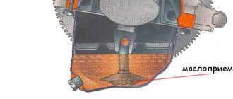
Engine (bottom view):
Removing the engine
Before removing the engine, disconnect the wire from the “—” terminal of the battery.
Drain : coolant, crankcase oil, gearbox oil
Recommendations: Remove the engine and gearbox assembly. When removing the engine, lower it down from the engine compartment. It is more convenient to remove the engine by placing the car on a lift.
EXECUTION ORDER
1.Unscrew the fastening bolts and remove the crankcase protection.
2. Remove the muffler exhaust pipe
3. Remove the air filter
4. Loosen the clamp and disconnect the brake booster vacuum hose from the engine inlet pipe.
5. Unscrew the bolt and disconnect the ground wire from the clutch housing.
6. Loosen the clamps and disconnect the hoses from the thermostat.
7. Disconnect the high-voltage wire from the central terminal of the ignition distributor cover.
8. Use a screwdriver to press out the spring clip and disconnect the block with low-voltage wires from the ignition distributor terminal.
9. Loosen the clamp and disconnect the fuel supply hose from the fuel pump.
10. Loosen the nuts on the end of the clutch release cable.
11. Remove the cable end from the clutch release lever.
12. Disconnect the block with the wire from the starter traction relay terminal.
13. Unscrew the fastening nut and disconnect the wire from the contact bolt of the starter traction relay.
14. Disconnect the block with the wire from the generator terminal.
15. Unscrew the nut and disconnect the wires from the generator terminal.
16. Disconnect the connector with the wire from the carburetor shut-off solenoid valve terminal.
17. Loosen the clamp and disconnect the fuel return hose from the carburetor. Remove the hose from the plastic clamp.
18. Loosen the bolt securing the choke rod to the choke control lever.
19. Loosen the bolt securing the air damper drive rod shell to the bracket and disconnect the cable.
20. Remove the spring clamp of the accelerator drive cable from the throttle valve drive sector.
21. Remove the throttle actuator return spring.
22. Remove the accelerator drive cable from the throttle valve drive sector.
23. Unscrew the fastening nut and remove the accelerator cable bracket from the valve cover.
24. Disconnect the block with the wire from the limit switch of the forced idle economizer (EFH).
25. Disconnect the wire from the coolant temperature sensor.
26. Disconnect the wire from the oil pressure sensor.
27. Loosen the clamp and disconnect the heater supply hose.
28. Loosen the clamp and disconnect the heater outlet hose.
29. Loosen the clamp and disconnect the gear shift rod from the joint tip.
30. Unscrew the fastening nut and disconnect the cable from the speedometer drive.
31. Disconnect the block with the wire from the reverse light switch on the gearbox.
32. Loosen the nuts securing the left and right braces to the suspension arms.
33. Unscrew the three bolts securing the brace bracket to the body and move the left and right braces to a position so that they do not interfere with the removal of the power unit.
34. Remove the cotter pin from the tie rod ball joint nut to the swing arm.
35. Unscrew the nut securing the steering rod ball joint.
36. Press the steering rod ball joint pin out of the strut swing arm using a special puller.
37. Remove the two bolts and disconnect the ball joint of the suspension arm from the steering knuckle.
38. Using a pry bar, press the shank of one of the inner CV joints of the drive shafts out of the gearbox and move it to the side.
39. Insert a technological mandrel (for example, an old internal CV joint) instead of the hinge so that the side gear does not turn. After this, disconnect the second CV joint in the same way as the first.
40. Unscrew the three mounting bolts and remove the clutch housing shield. The operations specified in paragraphs 40 and 41 are performed to facilitate work on the removed engine with the gearbox.
41. Loosen the three bolts and nuts securing the clutch housing to the cylinder block.
42. Hook the engine onto the eyelets and tighten the hoist cables.
43. Unscrew the two nuts securing the rear support of the power unit to the body.
44. Unscrew the nut, slightly lift the engine and remove the bolt of the right front power unit support.
45. Unscrew the nut and remove the bolt of the left front support of the power unit.
46. Lower the engine onto stands, lift the car and remove the engine from under it.
Before lowering the engine, check that all wires and hoses are disconnected from the engine.
Source
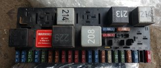
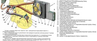
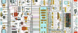
Wiring diagram for VAZ-2109 carburetor
- Headlight.
- Electric motor for headlight glass cleaning system. An optional part, used mainly on export vehicles.
- Limit switch for powering the engine compartment lamp.
- Klaxon.
- An electric motor drives a fan installed on the radiator of the cooling system.
- Temperature indicator that provides a control signal for the electric drive of the fan impeller.
- Alternator.
- Fluid supply valve for headlight glasses. Used in conjunction with paragraph 2.
- Fluid supply valve for the glass of the fifth door.
- Fluid supply valve to the front glass.
- Spark plugs.
- Hall sensor used to distribute ignition pulses.
- Coil.
- Limit switch for reverse gear lights.
- Fluid temperature meter in the cooling system.
- Starter.
- Accumulator battery.
- A sensor that measures the fluid level in the brake booster.
- Switch that controls the ignition system.
- Sensor for determining the position of the top dead center of the piston of the first cylinder. Installed on some export VAZ 2109 with a diagnostic system. Found only on cars before 1995.
- Diagnostic block. Optional element, installed together with item 20.
- Controller for controlling the solenoid valve installed in the carburetor.
- Starter switch contact block.
- Limit switch on the carburetor.
- Economizer valve.
- Sensor signaling an emergency decrease in oil pressure.
- Washer pump drive.
- Fan impeller motor for ventilation and heating systems.
- Resistance providing additional fan speeds.
- Speed shifter.
- Windshield wiper drive.
- Cigarette lighter.
- Illumination system for levers for adjusting heater operating parameters.
- Socket for additional equipment.
- Lamp for auxiliary lighting of the engine compartment.
- Illumination system for the glove box on the instrument panel.
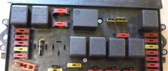
- Relay and fuse link mounting block.
- Instrument panel light switch.
- Parking brake lamp limit switch.
- Brake lamp limit switch.
- Steering column switch lever block.
- Exterior lamp switch.
- Hazard switch.
- Turn on the rear fog lamp.
- Bimetallic fog lamp fuse.
- Heated glass switch on the fifth door.
- Turn signal repeaters on the front fenders.
- Central interior lighting.
- Individual lampshade.
- Switches for backlight operation on the middle pillars.
- Ignition switching unit.
- Egnition lock.
- “Low” type instrument cluster.
- Choke limit switch on the carburetor.
- Rear lights.
- Fuel level meter in the tank.
- Heated glass.
- Rear wiper drive.
- Two lamps for room illumination.
Car engine structure
The cars are equipped with four-cylinder, four-stroke carburetor engines of various cylinder capacities, with an in-line arrangement of cylinders and a camshaft located on the cylinder head. The engine is specifically designed for transverse mounting in a front-wheel drive vehicle. Therefore, its layout and main dimensions were chosen such that it, together with the gearbox, could be placed transversely between the mudguards of the front wheels. Three unified engines with a working volume of 1100, 1300 and 1500 cm 3 are formed by a combination of three blocks of different heights and diameters of the cylinders, two cylinder heads with intake ports of different diameters, as well as two pistons differing in diameter (76 and 82), and two crankshafts shafts with crank radii corresponding to piston strokes of 60.6 and 71 mm.
When assembled with the gearbox and clutch, the engine forms a single rigid unit - the power unit. It is installed on the car on three elastic supports. They perceive both the mass of the power unit and the loads that arise when the car starts, accelerates and brakes. Elastic supports absorb vibrations from a running engine and do not transmit them to the body, thereby reducing noise inside the car. On the other hand, elastic supports protect the power unit from sudden impacts when the car moves over uneven roads.
The car uses a three-point mounting scheme for the power unit, consisting of front, rear and left supports. The front and left supports have the same structure and consist of an outer steel ring and an inner aluminum bushing, between which there is rubber vulcanized to them.
Device of the VAZ-21099 car
Cars VAZ-2108, VAZ-2109 and modifications based on them are primarily front-wheel drive passenger cars. Their layout is characterized by a front and transverse arrangement of the power unit (engine assembly with gearbox, final drive and differential). From it, torque is transmitted to the front wheels using shafts of unequal length, at the ends of which constant velocity joints are installed.
The front drive wheels create high vehicle stability against lateral skidding. The coincidence of the direction of the traction force on the front drive wheels with the direction of movement of the wheels provides the vehicle with good controllability, maneuverability and maneuverability, especially on slippery and icy roads.
The front-wheel drive layout, compared to the rear-wheel drive, allows for more complete use of the length of the vehicle and reduces its weight, making the interior and seating of the driver and passengers more comfortable. The useful volume of the car increases without increasing its dimensions. This is explained by the fact that there are no intermediate links of the transmission (propeller drive, rear axle) and therefore there is no need for a gearbox housing, which occupied significant space in the footwell on rear-wheel drive cars, and a large tunnel on the floor for the driveshaft. On front-wheel drive vehicles, a small floor tunnel houses only the exhaust system and the parking brake actuator.
The rear of the car is also very compact. The fuel tank 20 is located under the rear seat, and the spare wheel 14 is located in a niche in the trunk floor. Thanks to this, a significant amount of luggage space is obtained. The wedge-shaped shape of the body improves its aerodynamic characteristics, i.e. reduce air resistance when the car is moving. This is facilitated by the smoothed outer surfaces of the body, the large slope of the front and rear windows, as well as the smooth transition of the outer surface of the front bumpers into the formative surface of the body.
Low aerodynamic drag, a new, more economical engine, as well as the installation of new tires with reduced rolling resistance, made it possible to achieve low fuel consumption. A decrease in fuel consumption is closely related to a decrease in vehicle weight; for every kilogram of the vehicle’s own weight, it costs approximately 20 g of fuel per 100 km of travel. The weight reduction was facilitated by both the front-wheel drive layout of the car (the absence of a heavy rear axle and cardan drive), as well as the rational power structure of the body, the widespread use of lightweight plastics and new structural materials.
Bumpers, various casings, heater parts, interior and trunk lining are made of plastic. The weight of plastic parts reaches 80 kg. The radiator and many gearbox parts are also made of aluminum alloys, which also made it possible to reduce the weight of both the power unit and the car as a whole.
Engine. The car has a new engine, specially designed for a transverse arrangement, for which its length is reduced as much as possible. The selection of the optimal combustion process, valve timing, combustion chamber shape and gas channels all made it possible to increase the compression ratio in the engine to 9.9. In combination with a new carburetor and contactless ignition system, this improved engine efficiency. The engine cooling system is liquid closed type with forced circulation of liquid.
The coolant pump is an original design, located in the front of the cylinder block and driven by the camshaft drive belt. Aluminum radiator with plastic tanks.
The engine lubrication system has an original oil pump with internal gears. The pump is located at the front end of the crankshaft and does not have any additional drive. The oil filter is unified with that used on the VAZ-2105. A fine fuel filter is installed in the power system. To stabilize the pressure at the inlet to the carburetor, a return fuel branch is provided to drain excess fuel back into the tank. A new carburetor has been used, providing economical mixture formation at various engine operating modes.
The engine ignition system is electronic non-contact. The non-contact sensor in the ignition distributor sensor is based on the use of the Hall effect, the ignition timing correction is mechanical, due to centrifugal and vacuum regulators. The electronic ignition system increases engine stability at low speeds and improves its efficiency.
The car's transmission is simple, compact and reliable. It is combined into a single unit consisting of a clutch and gearbox with final drive and differential. The compactness of this unit made it possible to position the power unit across the vehicle and drive the front wheels directly from the gearbox, which allows the most efficient use of engine power and reduces fuel consumption. The transmission has retained the high reliability and performance of previous models and at the same time the overall weight and noise level have been reduced.
The gearbox is made according to a two-shaft design. All forward gears are synchronized. Most gearboxes are produced in a five-speed version, but production of four-speed gearboxes is also envisaged. The use of low-viscosity motor oil in the gearbox reduces losses during torque transmission and makes it easier to start the car in winter. The clutch is a single-plate dry clutch with a diaphragm pressure spring and increased wear resistance of the friction linings. The clutch is driven by cable, which makes it simpler. There are no gaps in the drive, and the clutch release bearing is constantly pressed against the diaphragm spring with a force of 5-7 kgf.
Wheel suspension. The cars use a fundamentally new suspension of the 27 front wheels of the “swinging candle” type, also called the “MacPherson” suspension after the inventor. The spring in such a suspension is located actually above the axis of the rotating device and is loaded less than in a double-lever type suspension. The suspension has only one lower control arm. The suspension is compact and light weight. greater wheel travel and more elastic. The rolling arm of the front suspension is negative, since the point of intersection of the wheel turning axis with the road surface lies outside the outer part of the car. This helps to increase vehicle stability when braking, when the left and right wheels have different grip on the road surface, and also reduces the influence of traction forces on the steering.
The suspension of the front wheels is in good agreement with the rear suspension 19 of two levers swinging in the longitudinal plane, connected to each other by a cross member, which plays the role of a stabilizer. The elastic element in the rear suspension, just like in the front, is coil springs.
Steering. With the transverse arrangement of the power unit and the MacPherson-type front wheel suspension, the steering system 25 with a rack and pinion steering mechanism is well combined. It does not require intermediate levers, is compact and simple in design. The tie rods are attached to the central part of the steering mechanism, which simplifies the design of the steering drive, since only two ball joints are used. This type of steering provides a small force on the steering wheel (9-12 kgf).
The braking system has efficient front disc and rear drum brakes. Brake drive with vacuum booster, dual-circuit, with diagonal separation of circuits. One circuit serves the brake mechanisms of the left front and right rear wheels, the other - the right front and left rear wheels. This separation of circuits is the simplest and meets the requirements for brake efficiency in the event of failure of one of the circuits, when the car maintains a straight direction of movement and no more than 50 percent is lost. braking efficiency.
The body is a three-door, two-volume hatchback type. It combines the versatility of a utility vehicle with the sweeping lines of a sports car. The luggage compartment is separated from the passenger compartment by a folding plastic shelf installed behind the rear seat. The body can easily be transformed into a cargo-carrying passenger version by folding the rear seat cushions and backrest forward. Large side doors provide easy entry and exit for passengers, while the rear door makes loading and unloading luggage easy.
Anatomical front seats with headrests significantly increase comfort. They, like the rear seat, are made of polyurethane foam with knitted upholstery. The continuously variable adjustment mechanism allows you to smoothly adjust the inclination of the backrests of the front seats. In addition, the front seats can be moved forward and backward, both to select their optimal location and to ensure comfortable seating for passengers in the rear seat. Due to the development of the power circuit of the body frame, high strength of the body and “soft” damping of impact energy in the event of an accident have been achieved.
So, in the event of a frontal impact on a stationary obstacle at a speed of about km/h, the windshield remains in the opening, the doors open easily, and the movement of the steering wheel into the passenger compartment does not exceed 90 mm. The power structure of the body guarantees the preservation of the vital space of the interior during impacts from the front, rear, side and when turning over onto the roof.
High corrosion resistance of the body is achieved primarily by using zinc-coated steel on all corrosion-hazardous parts: floor cross members, door sill parts, etc. Weld seams are sealed with special mastic. In addition, an increase in corrosion resistance is achieved with cataphoretic primer, special treatment of closed cavities and the application of an epoxy protective coating during final processing of the body.
The electrical equipment is almost completely original. Electronics and specialized integrated circuits (voltage regulator, ignition system switch, signal relays) are widely used in devices and components. The vehicles are equipped with a low-maintenance or maintenance-free battery, a small-sized starter with an end-mounted commutator, an electronic non-contact ignition system, a system of built-in sensors with instruments that monitor the operation of the most important vehicle systems. A new econometric device has been introduced, which allows you to select the most economical driving mode. In addition to control devices, cars are equipped with a special diagnostic system.
The connector for turning on the diagnostic equipment of service stations is located under the hood. It is connected to all control points of the electrical system. The diagnostic system allows you to examine the technical condition of the generator, voltage regulator, ignition system, battery, etc. The electric windshield wiper has three operating modes: two constant (but with different speeds of movement of the brushes) and one intermittent. Headlight cleaners are installed on some manufactured vehicles. To improve the performance of the cleaners, there is a glass washer.
Features of the device of the VAZ-2109 car. The VAZ-2109 differs from the VAZ-2108 in its five-door body and minor changes in the engine power system. The engine is equipped with a cold air intake that takes air directly under the radiator trim. It is made of polypropylene and mounted above the radiator of the engine cooling system. The intake is connected to the air filter brake regulator by a polypropylene air duct; the body frame is of a different shape, with two openings for the front and rear doors.
The front side doors and their mechanisms have the same structure as the doors of the VAZ-2108 car, the only difference is in size. The rear side doors are similar in design to the front doors, but differ slightly in the design of the door locks. The locks are not locked from the outside with a key and are equipped with an additional lock against opening the lock from the inside. The lever for this lock is located at the end of the door under the outer lock. If you move the lever down before closing the door, it will be impossible to open the door from the inside. It will only open with the outside door handle.
Features of the device of the VAZ-21081 car. This car is equipped with a VAZ-21081 engine with a reduced displacement (1.1 l) and only a four-speed gearbox. The body and all other components and mechanisms are the same as on the VAZ-2108 car. The engine (compared to the 2108 model) has a different cylinder block, cylinder head, crankshaft and camshaft. Due to the reduced engine displacement, a carburetor with different calibration data is installed, as well as a slightly modified exhaust system.
Features of the design of VAZ-21083 and VAZ-21093 cars. These cars differ from the VAZ-2108 and VAZ-2109 cars by installing a more powerful 21083 engine with a displacement of 1.5 liters. In addition, they only use a five-speed gearbox. Some vehicles may have a digital ignition system installed. Engine 21083 has a cylinder block with an increased cylinder diameter (82 mm). The diameter of the pistons and the diameters of the intake valves and channels in the cylinder head have also been increased. The carburetor is installed with different calibration data.
Features of the design of VAZ-21099 cars. The VAZ-21099 car differs from all the cars described above in its four-door sedan-type body. Its body is three-volume, that is, it is divided by partitions into three volumes: the engine compartment, the interior and the luggage compartment with a volume of 0.43 m^2. In terms of design and layout, the VAZ-21099 car is completely similar to the VAZ-21093 car (except for the rear part of the body). It is also equipped with a 21083 engine with a displacement of 1.5 liters and a five-speed gearbox. It is possible to install an instrument panel.
continuation>>
Announcements of articles from friendly sites
Cylinder block
All engine cylinders are combined together with the upper part of the crankcase into one common unit - a cylinder block cast from special high-strength cast iron. This arrangement ensures structural strength, rigidity, compactness and reduces engine weight. Coolant passages are made along the entire height of the cylinder block, which improves cooling of the pistons and piston rings and reduces deformation of the cylinder block from uneven heating.
The block cylinders are divided into five classes by diameter at 0.01 mm intervals. designated by the letters A, B, C, D, E:
| Class | Engine cylinder diameter 21081, 2108, mm | Engine cylinder diameter 21083, mm |
| A | 76,000-76,010 | 82,000-82,010 |
| IN | 76,010-76,020 | 82,010-82,020 |
| WITH | 76,020-76.030 | 82,020-82,030 |
| D | 76,030-76,040 | 82,030-82,040 |
| E | 76,040-76,050 | 82,040-82,050 |
The cylinder class is indicated on the bottom plane of the block opposite each cylinder. The cylinder and the piston mating to it must be of the same class. During repairs, the cylinders can be bored and honed to accommodate an increased piston diameter of 0.4 and 0.8 mm.
At the bottom of the cylinder block there are five crankshaft main bearing supports with thin-walled steel-aluminum liners. The upper and lower liners of the middle (3rd) main bearing are without a groove on the inner surface. The remaining supports have upper liners with a groove on the inner surface, and lower ones without a groove. Until 1988, the lower shells of these bearings also had grooves.
The bearings have removable covers 2, which are attached to the cylinder block with self-locking bolts. The holes for the crankshaft bearings in the cylinder block are processed together with covers, which ensures high accuracy, the correct geometric shape of the holes and their alignment. Therefore, the bearing caps are not interchangeable and, to distinguish them, have marks on the outer surface (see Fig. 6).
The middle support has slots for installing thrust half-rings 12 (see Fig. 6). holding the crankshaft from axial movements. A ceramic-metal half-ring (yellow) is placed on the back side of the middle support, and an aluminum-steel half-ring is placed on the front side.
The axial clearance of the crankshaft should be 0.06-0.026 mm. If the gap exceeds the maximum permissible (0.35 mm), it is necessary to replace the half rings with repair ones, increased by 0.127 mm. It should be borne in mind that the grooves located on one side of the half rings must face the thrust surfaces of the crankshaft.
From below, the cylinder block is closed with a stamped steel crankcase 37. The crankcase has a baffle to calm the oil. A gasket made of cork-rubber mixture is installed between the oil sump and the cylinder block.
The clutch housing is attached to the rear end of the cylinder block. The exact location of the crankcase relative to the cylinder block and the alignment of the crankshaft and the gearbox input shaft are ensured by two centering bushings pressed into the cylinder block.
Cylinder head
Cylinder head 27 is common to four cylinders. cast from aluminum alloy, has wedge-shaped combustion chambers. Valve guides and seats made of cast iron are pressed into the head. The seats, pre-cooled in liquid nitrogen, are inserted into the sockets of the heated cylinder head. This ensures a reliable and durable fit of the seats in the head.
A special non-shrink gasket on a metal frame is installed between the head and the cylinder block. The head is centered on the cylinder block with two bushings and secured to it with ten bolts.
To uniformly compress the entire surface of the cylinder head gasket, to ensure a reliable seal and eliminate subsequent tightening of the bolts during vehicle maintenance, the cylinder head bolts are tightened evenly without jerking in four steps and in a strictly defined sequence (see Fig. 7):
In the upper part of the cylinder head there are five supports for the journals of the camshaft 17. The supports are detachable. The upper half is located in bearing housings 16 and 21 (front and rear), and the lower half is in the cylinder head. The mounting bushings for the camshaft bearing housings are located at the housing mounting studs. The holes in the supports are machined together with the bearing housings, so they are not interchangeable, and the cylinder head can only be replaced assembled with the bearing housings.
A KLT-75TM type sealant is applied to the surfaces of the cylinder heads mating with the bearing housings in the area of the outer camshaft supports. Install the bearing housings and tighten the nuts securing them in two steps.
Valve distribution phases During one working cycle, four strokes occur in the engine cylinder - intake of the combustible mixture, compression, power stroke and exhaust gases. These strokes are carried out in two revolutions of the crankshaft, i.e. each stroke occurs in half a turn (180°) of the crankshaft.
Engine structure of the VAZ 2109
Engine VAZ 2109 top view:
Engine VAZ 2109 bottom view:
1 - generator, 2 - right front support, 3 - engine, 4 - gearbox, 5 - starter, 6 - reverse light switch, 7 - extension, 8 - left front support, 9 - left front wheel drive, 10 - gearbox oil drain plug, 11 — rear support, 12 — gear shift rod, 13 — oil sump, 14 — right front wheel drive, 15 — engine oil drain plug
VAZ 2109 bottom view photo
Rice. 1–2. VAZ-2109 engine compartment (top view):
Rice. 1–3. VAZ-2109 engine compartment (bottom view):
Rice. 1–2. Engine compartment of VAZ-2109 (top view):
1 –
engine
2 –
washer reservoir
3 –
air filter
4 –
fuel pump
5 –
vacuum booster
Rice. 1–3. Engine compartment of VAZ-2109 (bottom view):
The VAZ-2108 body has a three-door all-metal welded load-bearing structure. The car has both passenger and cargo-passenger body options. VAZ-2109 has a five-door Kuzoa. The outer and inner side panels have openings for the front and rear doors. The remaining parts and elements of the VAZ 2109 body frame are structurally no different from the VAZ 2108 body frame.
Body frame and tail
The main elements of the frame include the following elements: front end, floors, sides, roof with wind window frame, rear, load-bearing elements of the frame (spars, cross members, racks). Body plumage parts include the following body parts: front panels of the body and mounted components (front doors, hood, tailgate, front fenders).
All parts and components of the body, except for the hinged ones, form a single whole, welded by resistance spot welding, and heavily loaded parts are additionally welded by electric arc welding. The front of the body consists of a vertical front panel (49), front wing mudguards (4), cross members 1 and 54, radiator frame panel (55), front side members (50), connectors, struts (51), air intake box and other small parts. The air intake box is welded to the front panel. The body floor includes front (44), middle (38) and rear (30) floor panels. The front floor panel is trough-shaped, and in the middle there is a tunnel for exhaust system pipes, pipelines and fuel lines. The tunnel protects them from damage. The rear floor panel has a one-piece stamped niche for a spare wheel. Along the entire floor, side members are welded, which form single hidden longitudinal cavities along the bottom of the entire car with the front (50) and rear (35) side members. There is good access to both the side members and the hidden cavities. The front (46), middle (36) and rear (29) cross members, as well as reinforcements and floor extensions are welded to the floor.
PP lever shakes at idle
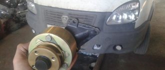
Is the handle jerking? Check the engine mounts
A jerky shift lever at idle is a fairly common occurrence if your car is old. Few people associate this problem with the power unit, but in vain. This symptom indicates excessive wear of the engine mounting pads. And if the problem is not eliminated, the engine will sag, and other complications will appear - difficult gear shifting, severe shaking of the front of the car when driving and increased wear of constant velocity joints (CV joints). As a result, CV joints will have to be changed every 5,000 kilometers.
Procedure for replacing engine mounts on a VAZ 21099.
Replacement of the power unit supports has been completed. If it is not possible to hang the motor on hoists, you can place a wooden board under the crankcase and lift the engine using jacks placed under it.