Popularly, a distributor is called a sensor-distributor or a breaker-distributor, it all depends on the design of the ignition system. The distributor is designed for commutation with the ignition coil (transmitting a signal to the switch) and distributing the ignition spark to the spark plugs. The design of distributors with contact and non-contact ignition systems is almost the same. The main components of the distributor are a breaker or sensor and a distributor. For the VAZ 2109, the diagram of the distributor with a hall sensor is shown in the top figure. The breaker serves to switch the coil for contact ignition or serves as a sensor in contact transistor ignition. The device of the breaker and sensor is almost identical. The only thing different about the VAZ 2109 is the contacts or sensor instead.
Detailed structure and principle of operation of the distributor
Let's start looking at the VAZ 21093, distributor diagram (below) with a contact group:
- The breaker is assembled from the following parts: housing (photo above), shaft, slider, contact plate with weights and springs, vacuum octane corrector, capacitor
- The shaft itself is made of two parts movably connected to each other
- There are cams on the upper or lower part of it, it all depends on the design, the number of cams corresponds to the number of cylinders
- Both parts of the shaft are movably connected to each other by means of a centrifugal octane corrector, which is assembled from cams, as well as springs of varying degrees of rigidity
- When the shaft rotates, the cams diverge under the influence of centrifugal force, while the springs stretch and only the upper part rotates relative to the bottom at a certain angle
- And the vacuum octane corrector is connected through a rod to a contact plate and a vacuum tube is connected to the intake manifold
- When opening occurs, then the air vacuum in the intake manifold increases, which leads to the rotation of the movable contact plate relative to the cams
- To reduce sparking and increase the secondary voltage, there is a capacitor on the distributor body, which is connected to the electrical circuit parallel to the contacts
- And on the top of this shaft there is a rotor (popularly called “runner”), which is designed to distribute high voltage current to the spark plugs; distribution occurs through the terminals on the distributor cover
What is the difference between the distributor device on a VAZ 2109 with a hall sensor:
- The distributor of VAZ cars with a contactless ignition system is distinguished by the complete absence of contacts in its design; their role is played by an electronic switch
- Here, instead of contacts in the distributor, a sensor is installed, the operation of which is based on the effect discovered by Hall, who studied the behavior of semiconductors in an electromagnetic field
- A sensor with a special slot is installed on the movable plate of the distributor
- This slot contains a permanent magnet on one side and a semiconductor on the other side.
- A metal shutter is installed on the distributor shaft, having a rectangular slot, which during rotation passes through the sensor slot; it blocks the magnetic flux going to the semiconductor from the magnet
- At this time, the sensor stops passing the current passing through it to the switch
- Rotating further, the curtain passes the cutout past the sensor and then the semiconductor enters the field of action of the permanent magnet, and then passes a current that passes to the output of the switch
- And the switch, depending on this, opens or closes the power transistor, through which the terminal from the ignition coil is connected to ground
So we looked at the VAZ 2109 distributor device, and the principle of operation; in order to disassemble it and repair it, you will need another article. Drivers often have to deal with adjusting the ignition timing, I think it will be useful for you to know this too.
Setting the ignition timing
After we have studied the distributor device on the VAZ 2109, we move on to adjusting the ignition timing. To complete this job you will need:
- Crooked starter or ratchet wrench
- The slotted (flat) screwdriver is durable and has a powerful, wide blade
- Set of probes
- Open-end wrench “12x13”
- Conical rubber plug
- A spark plug wrench or a suitable socket with a wrench instead
Preparing for adjustment
In order for the engine of your car to work as expected, it is necessary that a spark jumps at the right time, which would ignite the mixture by the time the piston passes TDC and the gas, having completed the work of expansion, pushes the piston down. To ensure that the spark occurs on time, the ignition system uses a distributor, the main components of which are a contact group and a slider. The most important adjustments for cam ignition are: the gaps between the cams, the angles of the closed state of the contacts (UZSK) and the ignition timing. Before you start setting the ignition timing with your own hands, you need to make sure that:
- The spark plugs are in good condition and suitable for further use.
- If they have oil deposits on them, then it is recommended to calcinate them.
- It is not recommended to use sandpaper for cleaning, even fine sandpaper; fine abrasive from it may remain on the ceramic insulator and, as a result, the spark plug will begin to pierce
- It is not at all necessary to ignite the candles red hot, the main thing is to burn off the oil deposits
- Then we will adjust the gaps of all spark plugs in accordance with the manual
- To do this, use a wire probe
- We definitely check the condition of the contacts of our breaker
- If there are signs of metal burnout or signs of corrosion, replace the contacts
- It is not recommended to repair them, for one simple reason: after repair, the contacts will not last long! It’s easier to replace them and forget them for a long time
- We check the capacitor using a tester for charge and discharge
- The current should flow smoothly and slowly
- To do this, it is better to use a pointer tester, it can be seen more clearly
- You need to make sure there is good contact in the main wire coming from the ignition coil.
- By the way, it doesn’t hurt to check it either
- You can also check with a tester, megger, or the easiest way and completely free of charge at a good auto parts store on the stand
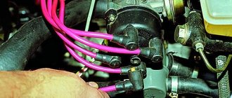
- We remove dirt from the ignition coil, distributor cap and distributor
- If carbon deposits have formed on the distributor cap, it must be replaced.
- Don’t save money, take a branded factory cover, the price will be paid off by the quality
- We carefully assess the condition of the carburetor
- If the carburetor does not respond to adjustment, it is time for repair. But this is a separate article
- Checking the operation of the vacuum ignition timing
- So that its drive runs without jamming, and the tube is thick-walled without cracks or breaks
We insert the breaker-distributor itself
Having made sure that all elements of the system are in good working order, we proceed to the adjustment, first consider the situation when the distributor was removed entirely:
- Now, in order to insert it into place, you need to select one of the 1st or 4th cylinders in which the piston moves in the compression stroke at TDC when the marks of the crankshaft pulley and the front cover are aligned
- This is done simply. We take a rubber cone plug, unscrew the spark plug of the first cylinder, insert the plug into the spark plug hole, tighten it
- Smoothly rotate the crankshaft with a crooked starter or ratchet wrench
- As soon as the desired (the first in our case) cylinder comes to TDC, a rubber plug comes out of it
- I advise you to immediately tie the cork so that you can look for it for a long time later
- Now we combine the marks on the pulley and the front cover (with the longest one)
- Then we insert the distributor strictly along the slots so that the slider stands evenly and perpendicular to the plane of the engine head and looks at it
- Then we raise the distributor a little bit to make it possible to rotate the shaft and not catch the splines, and rearrange it clockwise by one tooth
- We do this to give the distributor the fullest possible stroke for adjustment.
Direct adjustment
Adjustment instructions when the distributor is in place:
- It is necessary to set the gap between the contacts, strictly according to the car manual
- For classics this gap is 0.45
- Angles of the closed state are set only on special testers, so you don’t need to set them yourself, it just won’t work
- We connect all the wires as expected and set the torque adjustment in the middle of the stroke
- Then insert the spark plug of the 1st cylinder into the spark plug wire corresponding to the first cylinder and turn on the ignition
- Rotate the pulley counterclockwise about 45 degrees
- Then we create ground contact for the spark plug and smoothly rotate the pulley in a clockwise direction
- As soon as a spark jumps between the electrodes, stop rotating the crankshaft
- Checking the marks (on the cover and pulley)
- If there is a run-up between them, you need to turn the distributor one to two degrees in the required direction
- When the pulley mark runs forward from the front cover mark in the direction of rotation, it means that the ignition is late and the distributor should be turned counterclockwise
- When the mark, on the contrary, does not reach the mark on the cover, it means that the ignition is early and the distributor should be turned clockwise
- Next, we repeat the previous procedure with rotating the pulley back and again catch the moment the spark jumps, compare the marks and adjust
- With some experience everything will turn out quickly and easily
Advice: the more carefully and slowly you rotate the pulley, the more accurately you will be able to set the ignition
- When we have reached an exact match of the marks, tighten the distributor and turn the crankshaft two full turns, then check the adjustment again
- When a run-up appears, eliminate it; if everything matches, start the engine and warm up
- Next, we accelerate the car to a speed of 40-50 kilometers per hour, and engage fourth gear, then sharply press the gas
- If you suddenly hear the sound of valves busting, then the ignition should be set later
- Typically, fine adjustments do not require further adjustments.
Quick method
A faster method is suitable for starting the engine for the first time after repair:
- Install the distributor in place according to the principle described above
- It’s easier to set the advance torque
- Having found the TDC of the piston of the 4th cylinder, we combine the crankshaft mark with the middle mark on the cover
- Then we turn the distributor slowly clockwise and counterclockwise, as soon as a spark jumps, we stop and fix the distributor
- Ignition set
We set the advance using the strobe light
There is a way to adjust the ignition using a strobe light. It is the simplest and most accurate, but depends on the serviceability of the device. All stroboscopes are different in design, however, they all have the same operating principle:
- We connect the wires supplying the strobe to the terminals, and the wire that receives the pulses to the spark plug cap without removing it
- The setting is performed at idle speed
- Point the strobe light at the hole (hatch) in the clutch housing (see)
- It is better to mark the mark on the crankshaft flywheel with a bright white marker or corrector
- We point a strobe light at the pulley and, under the influence of flashes emitted by the strobe light with a certain frequency, we see the marked mark stationary
- Rotate the distributor in the required direction until the required marks coincide and fix it
Warning: If the mark under the strobe beams moves back and forth, this indicates a malfunction of the ignition system (usually the capacitor or contacts).
Now that the adjustment is complete, a video on this issue will clarify all unclear points.
The saying that new is not the best is not always true. If we talk about ignition systems, it does not apply here. The old, proven over the years, cam (contact) ignition system has already been forgotten, as it has been replaced by a contactless one, which is not only newer, but also more practical, more efficient, and more reliable. But what are the advantages of each system? This is something worth understanding in more detail and making a final conclusion about which is better.
Cam ignition system
So, the ignition system, tested by more than one generation of car and motorcycle enthusiasts, is quite functional and was widely used on the VAZ, for example. If you have driven cars with such an ignition system, you know how important it is to correctly set the gap in the contact group. Make a little mistake and you won't see a good spark.
But there is one big advantage to this system. Of course, this is simplicity, since there are no electronic components whose reliability is in doubt. As a chopper: cam mechanism, high-voltage coil and ignition distributor with ignition timing correction. Simple, and most importantly - cheap.
But the disadvantages affect the entire structure. At the moment of disengagement, a spark is formed, which has a detrimental effect on the metal contacts. They are coated with black, which impairs contact. For this reason, a spark does not form on the spark plugs, and the engine cannot be started. You have to make contacts and adjust the gap from time to time.
What types of ignition coils are there?
Based on their purpose:
- Having no contact.
- Contact.
If your car does not have a distributor, the spark plug coil is 100% contactless. For customized coils, only this type is provided. But if the distributor has special equipment - in the form of breaker contacts - you use a contact-type ignition system.
If the criterion is the number of spark plugs available, they are divided into:
- Are common.
- Individual.
There are also differences in winding insulation options . They are:
- Filled with oil. The housing contains metal; transformer oil is used to insulate the windings. If the housing loses its seal, this device will simply stop functioning. The leakage of such oil leads to interturn electrical breakdown of the windings (since they are absolutely not protected).
- Dry (filled with compound).
Contactless ignition system
Contactless (electronic) ignition was installed on VAZ cars starting from the eighth family. The advantage of the system is that a Hall sensor is used as a breaker. There are no contacts, but there is a more vulnerable spot - the switch, whose task is to amplify the signal from the sensor. The switch is made on semiconductor elements, which is not always reliable. Most motorists prefer to carry a spare switch and Hall sensor with them in the car.
These are two elements of the ignition system that fail and cannot be repaired. But on the other hand, the contactless system is much more efficient than the cam system, and it lasts longer. A high-quality Hall sensor and switch can last for many years and will never fail. And they do not need any care. It is only important that the switch is firmly installed on the body for better cooling. And the wires from the Hall sensor, which are located inside the ignition distributor, did not come into contact with moving parts.
Having assessed all the pros and cons, we can say that a contactless ignition system will be much better than a cam ignition system. It requires a minimum of maintenance and is quite effective in its work. And the cam is outdated at the moment and needs frequent adjustment of the gap and cleaning (replacement) of the contacts.
Good day, all car enthusiasts! Friends, you know better than anyone else that literally every driver, day and night, strives to improve his own vehicle. Absolutely any component of the car can undergo tuning, from the trunk lid, on which we so love to mount the ever-popular spoiler, to the engine, whose power is increased in a variety of ways. Today, we will look at neither one nor the other under a microscope - contactless ignition. We will learn the principle of its operation, its structure, possible malfunctions, and in the end, friends, you will receive a master class on installing the mechanism from your humble servant.
The “lion's share” of those present here certainly wondered, “What kind of tuning is this? This is the system I have, integrated into the standard kit.”
I’ll say right away that this publication will be of little use to owners of new modern cars, because a contactless ignition system is installed in absolutely every such model, regardless of the manufacturer’s brand. So, I will say more for the owners of some old foreign cars, as well as native domestic classics. If you are already quite tired of hearing about the various advantages of BSZ and “drooling,” it’s time to purchase the installation. Do you doubt whether it is relevant? Let's think together...
Electronic spark plugs
When installing BSZ on a VAZ 2106 model car, it is advisable to select and install spark plugs that are optimally suitable for electronic ignition. Along with Russian spare parts, the use of imported analogues from well-known brands is allowed:
- original spark plugs recommended by the manufacturer - A17DVR (M);
- NGK - BCPR6ES-9, BPR6ES-9;
- Bosch - FR7DCU, WR7DC;
- Brisk - DR15YC, LR15YC;
- Beru - 14FR-7DU, 14R-7DU.
The letter M in the marking of domestic parts indicates copper plating of the electrodes. There are A17DVR kits on sale without copper coating, which are quite suitable for BSZ.
The gap between the working electrodes of the spark plug is set within 0.8-0.9 mm using a flat feeler gauge. Exceeding or decreasing the recommended clearance leads to a drop in engine power and an increase in gasoline consumption.
Installing a non-contact spark generation system significantly improves the performance characteristics of carburetor Zhiguli cars equipped with rear-wheel drive. Unreliable, constantly burning contacts caused a lot of trouble to the owners of the “sixes”. At the most inopportune moments, the breaker had to be cleaned, getting your hands dirty. The first electronic ignition appeared on front-wheel drive models of the “eighth” family, and then migrated to the VAZ 2101–2107.
Why contactless is better than contact ignition
I know from myself that something new is not easy for a driver, for many it is much easier to tinker with old distributors, change this damn “contact group”, sometimes even on the road. I can understand that today, not everyone will be able to spend about 2-3 thousand rubles on their own car (VAZ kit), especially if the car functions well. Although, on the other hand, it’s not that much money for your favorite “swallow”, and this is a one-time investment! Believe me, there is nothing to be afraid of! It’s not for nothing that every second car is equipped with a contactless ignition system.
Please note: the contact group is designed to open and close an electrical circuit; it operates on the principle of mechanical contact, and accordingly wears out regularly, which significantly reduces the service life of the support bearing.
In order to finally convince the old “drivers” of conservative views of the advantage of a contactless system over a contact one, you just need to compare them with each other. This way we will find out which ignition is better, we will draw two parallels against the background of the advantages of BSZ.
Advantages of BSZ
- Simple installation and setup - in older systems, the procedure for adjusting the required gap at the contacts was
not given to every driver. - Reliability in operation - here it’s difficult to add something as a counterbalance, because the contact system “feverish” quite often.
- Excellent starting qualities - due to the fact that the current supplied to the primary winding of the ignition coil comes from a semiconductor switch, which in turn can significantly increase the spark energy; the voltage on the secondary winding of the same coil can reach 10 kV. All this adds up to help a lot in our cold winters.
- Higher power - the electromagnetic pulse generator that replaced the contact group (uses the Hall effect in its work) demonstrates excellent efficiency. Paired with an electronic switch, the purpose of which is to timely lock or unlock the transistor at the output, the mechanism operates clearly and stably at any speed of the power unit.
- Savings – per 100 km, up to one liter of fuel!
- Low power consumption - the load on the battery is significantly reduced even when the ignition is on, because the electrical unit requires power only after the shaft begins to rotate.
Please note: BSZ for injection and carburetor engines may differ.
If this is not enough, I will also note the rare need for maintenance of contactless ignition. The manufacturer requires lubricating the distributor shaft every 10,000 kilometers and this is, in principle, the only remark from the car plant. What is the difference is clear, I will also say about the weak point in the contactless system - these are switches, which more often than other parts fail.
BSZ structure
The contactless ignition system is a number of different mechanisms, namely:
- Ignition switch;
- Pulse sensor;
- Transistor switch;
- Ignition coil;
- Spark plug;
- Sensor-distributor (distributor);
- High and low voltage wires.
The structure of the contactless ignition system can be clearly seen in the photo; we will briefly analyze the principle of its operation.
As you probably already understood, the entire system is based on a Hall sensor, which, acting on the semiconductor with a magnetic field, creates a transverse voltage. This happens due to the slot design of the device, that is, a semiconductor (and a permanent magnet) is located on opposite sides of the hole.
A steel cylinder with slots rotates in the slot itself. Thus, when the sensor slot and the cylinder slots coincide, the magnetic flux acts on the conductor (through which, by the way, current flows when the ignition is on), then the resulting pulses act on the switch, after which they are converted into the current of the primary winding of the ignition coil.
Structure and functions of BSZ
Based on the figure, the operating principle of the system is briefly explained:
Drawing. Components of a transistor ignition system
- Accumulator battery
- Ignition and starter switch
- Ignition coil
- Switch
- Ignition sensor
- Sensor-distributor
- Spark plug
When the ignition (2) is turned on, supply voltage is supplied to the primary winding of the ignition coil (3). Current flows through the primary winding; as soon as the commutator (4) receives a signal from the ignition sensor (5), the current in the primary winding is interrupted. Terminal 1 of the ignition coil is connected to ground via a switch. A high voltage of more than 20 kV is induced in the secondary winding.
The secondary voltage of the ignition system is transmitted through terminal 4 of the ignition coil to the distributor sensor to the corresponding cylinder and spark plug.
The control unit determines the crankshaft rotation speed (sensor signals) and, based on it, controls the accumulation time of the current of the primary winding of the ignition coil (the duration of the open state of the output transistor or thyristor of the ignition system) and its magnitude. In accordance with the speed and voltage of the battery, shortly before the appearance of the ignition spark, the set value of the primary current is set, that is, as the speed increases, the duration of the current flow increases in the same way as when the battery voltage decreases.
When the ignition is turned on and the engine is not running (no sensor signal), after a while (usually after one second), the current in the primary winding of the ignition coil is turned off. As soon as the control unit receives a sensor signal (for example, during startup), it returns to operating status.
To adapt the ignition timing to different load conditions, adjustment is carried out in the same way as in contact ignition systems, mechanically through a membrane mechanism of a vacuum regulator, as well as a centrifugal regulator. As a result, the sensor signal (and with it the ignition timing) changes depending on the engine speed and load.
Drawing. Interaction diagram of vacuum and centrifugal adjustment when controlling the ignition using an inductive sensor
- Centrifugal regulator
- Vacuum ignition timing regulator with membrane mechanism
- Ignition distributor shaft 4 - Hollow shaft
- Ignition distributor inductive sensor stator
- Control pulse sensor rotor
- Ignition distributor rotor
Inductive signal formation in a contactless transistor ignition system by storing energy in inductance
As a result of rotation of the rotor of the control pulse sensor, the magnetic field changes and an alternating voltage shown in Figure a, b is created in the induction winding (stator). In this case, the voltage increases as the rotor teeth approach the stator teeth. The positive half-cycle of the voltage reaches its maximum value when the distance between the stator and rotor teeth is minimal. As the distance increases, the magnetic flux sharply changes its direction and the voltage becomes negative.
Drawing. Control pulse sensor based on the induction principle a) Process diagram
- Permanent magnet
- Core induction winding
- Variable air gap
- Control pulse sensor rotor
b) time characteristic of alternating voltage induced by the control pulse sensor tz = ignition timing
At this point in time (tz), as a result of interruption of the primary current by the commutator, the ignition process is initiated.
The number of rotor and stator teeth in most cases corresponds to the number of cylinders. In this case, the rotor rotates at a reduced crankshaft speed. Peak voltage (± U) at low speed is approx. 0.5 V, at high - approx. up to 100 V.
The ignition timing can only be monitored when the engine is running, since without rotation of the rotor the magnetic field does not change and, as a result, no signal is created.
Weaknesses of the system
It doesn’t matter at all what type of system is installed on your car - contactless electronic ignition, BSZ or a regular contact one, the problems in their operation can often be no different.
- Faulty ignition coil;
- Problems with candles;
- Open circuit in high or low voltage circuit.
The contactless transistor ignition system is distinguished by its own unique ailments.
- Transistor switch problems;
- Vacuum and centrifugal ignition timing regulator;
- Sensor-distributor.
Such malfunctions of the contactless system will, of course, immediately affect the operation of the car. So, if you have problems starting the engine, check the wiring, ignition coil or spark plugs. If the car is acting up at idle, examine the distributor sensor cover for holes, the device itself and the switch transistor.
If there is a significant loss of machine power or an increase in its consumption, pay attention to the condition of the spark plugs, vacuum and centrifugal voltage regulator.
Installation of BSZ
Installing contactless ignition is a completely accessible process, of course, for people with steady hands. Before you begin, be sure to make sure that the ignition on the old distributor is set correctly; if necessary, leave marks; otherwise, it is not recommended to start the procedure. So, there is a connection diagram for contactless ignition (in the photo), then let’s get started with what to do.
- We dismantle the distributor cover along with the wires; the central one from the coil also needs to be disconnected.
- Next, you need to set the slider exactly perpendicular to the power unit; to do this, jerkily engage the starter.
- We remove the old distributor.
- On the new one, remove the cover and install it in the seat.
- We adjust the distributor according to the marked marks and fix it.
- We replace the old coil with a new one.
- We connect all the wiring.
- Next, you need to install the switch; to do this, find a suitable place under the hood and secure it to the body.
- Check the work done with the diagram.
- Let's start the engine.
That's all, just 10 steps and about 3 thousand rubles and BSZ is already functioning on your car. And believe me, after this, the question “Which ignition is better?” will disappear by itself. Well, that’s all, the conversation about contactless ignition is coming to an end, but in the next publications we will examine in detail an equally important topic called “Ignition Module”. I'm sure everything worked out for you! See you later!
A car is a set of devices that create a spark and ignite the mixture of fuel and air inside the cylinder at the required moment in time. Since the beginning of its emergence it has been an integral part of them.
On modern cars they can be either contact or contactless, the main difference being the configuration. Otherwise, the operating principle of both systems is almost identical.
Characteristics of popular ignition coils
| Ignition coil | Transformation ratio | Design features | Applicability of ignition coils |
| B114-B | 227 | R, M, DR | ZIL-130, 131; GAZ-56, 66, 3102; PAZ, KAvZ |
| B115-V | 88 | R, M, DR | M-412, 2140, 2141; GAZ-24; ZAZ-968 and others. |
| B116 | 153 | R, M, DR | GAZ-2410, 31029 |
| B117 | 78.5 | R, M | VAZ-2101,…07, 2121 |
| B118 | 115 | R, M, E, DR | ZIL-131; GAZ-66, etc. |
| 27.3705 | 82 | R, M | VAZ-2104,...09, 2121; M-2141; ZAZ-1102 |
| 29.3705 | 90 | R, S | VAZ-2108, 09 (MSUD); VAZ-1111; VAZ-2110 |
| 3009.3705 | 70 | Z, S | GAZ-3302 (MSUD) |
| 3112.3705 | 80 | Z, S | VAZ-2107,...12; GAZ-31029 |
| 8352.12 | R, M | VAZ-2110,…12 |
P – open magnetic circuit; Z – closed magnetic circuit; M – oil-filled coil; C – dry coil; E – shielded coil; DR – the coil has additional resistance (0.9…1.0 Ohm)
Bobbins may differ in some minor nuances that affect the smooth operation of the engine. For example, a B-115V reel can be replaced with a B-117A. The characteristics of the B-115V and B-117A are almost identical. But the spark discharge current of the B-115V is more powerful - 38 mA, while the B-117A is only 30 mA. A powerful spark is better than a weak one, and replacing the B-115V with the B-117A does not lead to any negative consequences. But owners of cars with tachometers will find that the device readings do not coincide with the actual ones. This is due to the absence of an additional resistor in the 117 model. That is, replacing almost identical B-115V devices with B-117A, or vice versa, is not always correct.
If your car has a B116 ignition coil, then you should know that they are available in two modifications. For contact and non-contact systems. Modifications 03, 04 for contactless.
In modern cars, individual coils are more often used, for each spark plug separately. Individual step-up transformers for each spark plug significantly simplify the ignition system by eliminating the distribution module from the electrical circuit
The most popular manufacturers of such devices are:
- German company Bosch;
- Taiwanese Dynatec;
- Italian
But if the first company, Bosch, can be considered the general developer of devices, then the second Dynatec and ERA produce their clones, but at a fairly high technical level and are almost as reliable as the original, despite the lower price.
Contact ignition
Contact ignition system is the most authentic type of ignition. Its advantages include high reliability, low cost, ease of maintenance and maintainability, even in field conditions.
Currently no longer installed on production vehicles - it has been replaced by a newer contactless system as its performance is much better. However, debate continues among owners of older cars about which type is better, so many cars continue to use a system that uses the contact principle of operation.
The contact ignition system has one big drawback - the contacts themselves, which tend to heat up and also burn out during long-term and continuous operation. In addition, while the contacts are closed, voltage loss occurs, which leads to battery discharge and heating of the coil, even when the engine is not running.
Ignition coil reliability parameters
Before purchasing a new reel, try to find out its reliability, according to reviews from its owners. Ask about the mileage that the device has withstood, whether the engine response and fuel consumption, maximum speed and CO emissions have changed.
The coil design must ensure:
- reliable insulation between windings and turns;
- high electrical resistance between the body and ground;
- strength of the case, especially plastic parts;
- absence of microcracks;
- reliability of electrical contacts and connections.
A high-quality reel can withstand temperatures up to 180°C.
Compound
The contact ignition system includes the following components:
- The switch is also the central switch. This device is necessary to close and open the electrical circuit of the car.
- A mechanical breaker is a device that opens the main winding circuit on a coil (low voltage circuit). After this, a high voltage appears on the secondary circuit of the coil winding. A capacitor is connected in parallel to a single circuit with a mechanical breaker; this option helps to better operate the contacts, preventing them from burning.
- An ignition coil is a device that creates a low voltage current from a high voltage current, consisting of two windings - primary and secondary.
- Mechanical distributor - a device that distributes current to each individual spark plug. It consists of a rotor and a housing cover. The principle of operation of this unit is that from the central contact located on the housing cover, the voltage is directed to the side contacts, through which it is then supplied to the individual spark plugs. It is worth noting that traditionally the distributor and contact breaker are combined in a single body; car enthusiasts call such a device a “distributor”. The distributor is driven by transmitting torque from the engine crankshaft.
- A centrifugal regulator is a device for adjusting ignition timing. It consists of two suspensions that act on the plate in which the breaker eccentrics are located. If the advance angle is set incorrectly and the spark is not supplied in the uppermost position of the piston, the mixture in the cylinders will burn ineffectively, resulting in a decrease in engine power and an increase in the amount of harmful substances released into the atmosphere.
- Vacuum regulator, it is also designed to adjust the advance angle, but depending on the load on the engine, i.e., depending on the force of pressing the gas pedal.
- High voltage wires. These wires are needed to transmit current from the coil to all other components of the system.
- – this unit forms a spark between two contacts, which leads to ignition of the air-fuel mixture in the engine cylinder.
A complete diagram of the contact ignition system is shown in various photos, which can easily be found on the Internet.
What is an ignition coil and why is it needed?
In order for the charge applied to the spark plug to penetrate the distance between the two electrodes and generate a spark, a very high voltage is needed. The 12 volts the battery produces is not enough for this. Much higher indicators are needed - from 10 to 50 kV. Accordingly, a special device is required that would increase the voltage to the minimum required values. It is called a multiplier (or converter). The functions of such a device are performed by the ignition coil. It ensures increased voltage and timely spark formation. This is the main purpose of the part. In fact, the operation of the ignition coil determines whether the car’s engine can be started or not.
It should be noted that on some engines, in addition to the coil, a distributor is installed. Essentially, it is a voltage distribution switch. The main task of the device is to distribute high-voltage electric current between the cylinders.
Depending on whether this device is used in a car engine, it can be one of 2 types:
- reel;
- distributor
Note that, if desired, you can replace the distributor with a coil that does not require its presence. However, this is a rather complicated procedure, so its feasibility is questionable.
Replacing old with new
Many people, faced with problems caused by the contact ignition system, prefer to improve it or replace it altogether, but lovers of classic cars and car restorers prefer to keep the original. And this procedure is quite expensive - although the replacement work is quite simple and consists mainly of replacing parts and assembly, the kit itself is expensive.
The non-contact type is better than the contact type in that it is devoid of contacts, which often burn during prolonged use.
Unlike contact, contactless has a switch - this device replaces contacts, but performs the same functions. This is, in fact, the only difference between these ignition systems.
And lastly
It should also be noted that the non-contact type has better current characteristics - higher frequency and voltage, which significantly extends the life of the spark plugs. However, this difference also has its drawbacks - you will have to replace standard high-voltage wires with silicone ones, which conduct current better, but are much more expensive.
VAZ 2107 cars use two types of ignition: an outdated contact system and a modern contactless system. The latter type began to be used on VAZ classics relatively recently, mainly on models equipped with injection engines. However, the advantages of the contactless circuit are fully realized on VAZ carburetor engines.
Contact ignition system VAZ 2107
The classic contact system used on the VAZ consists of 6 components:
The ignition switch combines two parts: a lock with an anti-theft device and a contact part. The switch is secured with two screws to the left of the steering column.
The ignition coil is a step-up transformer that converts low voltage current into the high voltage needed to produce a spark in the spark plugs. The primary and secondary windings of the coil are placed in a housing and filled with transformer oil, which ensures their cooling during operation.
The ignition distributor is the most complex element of the system, consisting of many parts. The function of the distributor is to convert constant low voltage into high pulsed voltage with the distribution of pulses across the spark plugs. The design of the distributor includes a chopper, centrifugal and vacuum ignition timing regulators, a movable plate, a cover, a housing and other parts.
Spark plugs ignite the gasoline-air mixture in the engine cylinders using spark discharges. During operation of the cross sections, it is necessary to monitor the gap between the electrodes and the serviceability of the insulators.
How to check the ignition coil with a tester
Checking the ignition coil is a lengthy process consisting of external inspection and tests using measuring instruments. Reels are usually tested on special stands in service workshops or dealerships. If you need to take measurements in artisanal conditions, you usually use a multimeter - a universal device with a wide spectrum of action.
The ignition coil is located in the switch, so for testing you should bend the latched retainer and remove the cables from the switch. Then take a multimeter and set the settings necessary to check the voltage. Now you should attach one of the cables to the output of the reel, and the second to the car body.
The result of this measurement should be 12 V. If the machine has a malfunction in the electronic control system or the electrical circuit of the switch, then the multimeter will display a reading of 0 V.
Preparing for the test
Before testing the bobbins itself, a little preparation should be done. You need to purchase a multimeter (a device that can measure voltage and electrical resistance) and find the machine's user manual. Different cars may have different types of bobbins built in, and the indicators for a specific car are indicated in the passport. If the vehicle was purchased on the secondary market, it is worth trying to find the necessary data via the Internet.
To check the ignition coil you will need a multimeter with the ability to measure resistance and voltage
The indicators that should be looked for in the specified book are the resistance of the primary and secondary windings. If you couldn’t find them in the manual, then during the test it is better to be guided by the average data described in the article.
What resistance should be on the ignition coil
To determine the voltage of the device handle, it is set to a level of 200 Ohms. After this, the resistance of the primary winding is measured. The probes are applied to the “+” and “K” terminals.
For a working bobbin, numbers in the region from 0.2 to 3 ohms are considered normal. The exact numbers may vary depending on the specific type of reel and the accuracy of the multimeter. Contacts “+” and “K” allow you to get indicators in any situation.
For the primary winding, a resistance in the range from 0.4 to 2 Ohms is considered acceptable
Now the device is switched to settings of 20 kOhm. In this position, it is necessary to measure the resistance between “K” and the middle terminal of the high-voltage cable. To do this, poke the probe into the contact area (made of copper) inside the round hole for installing the high-voltage wire. Indicators on the device of a working bobbin will display from 2 to 4 kOhm.
Visual inspection
Typically, the external appearance of the reels differs in each specific model, but on each of them you can find the main parts - the box, contacts, cover and central clamp. To carry out a visual inspection, you only need to carefully look at the reel and determine its condition. If there are small cracks, chips, or scratches on the surface, then the reel is damaged. The outer box of the device is made of ebonite, which is unable to conduct current. Therefore, interruptions in the functioning of this part are usually associated with internal flaws.
Checking the primary winding
To perform testing, you need to set up a multimeter to measure electrical resistance. The contacts are then connected to the cables with plus and minus signs on the ignition bobbin.
Diagram for checking the primary and secondary windings of the ignition coil
If, after testing is completed, the multimeter displays numbers from 0.4 to 2 Ohms on the display, then the bobbin is in order and working properly. If the indicators differ from those indicated above, then the bobbin winding has broken.
Contactless ignition system VAZ 2107
The electronic ignition circuit of the VAZ 2107 received the name “contactless” because the circuit is opened/closed not by the breaker contacts, but by an electronic switch that controls the operation of the output semiconductor transistor. The electronic (non-contact) ignition system kits for the VAZ 2107 on carburetor and injection engines are somewhat different, so there is a misconception that electronic and non-contact ignition are different systems. In reality, the operating principle of electronic ignition systems is the same.
Like a contact ignition system, electronic ignition includes spark plugs, wires, an ignition coil and a distributor. The only difference is the presence of a switch that controls the supply of high voltage to the spark plugs.
The contactless system is characterized by increased reliability due to the absence of contacts that require cleaning and gap adjustment. A semiconductor transistor ensures stable spark distribution across the cylinders. Thanks to the high spark discharge voltage (25-30 instead of 9-12 kV), more complete combustion of the working mixture in the cylinders occurs, which improves the dynamic characteristics of the engine and environmental safety indicators of the exhaust. When the battery voltage is low, the voltage in the spark plugs remains high enough to ignite the mixture, which makes it easier to start the engine in severe frost.
Main components of the electronic ignition system
The main element of the electronic ignition system is the electronic unit. It is he who controls the ignition. By collecting and processing data according to the established algorithms, the module sends signals to the switch.
In addition, the main components include:
1. Switch. Consists of transistor switches. Most advanced vehicles have multiple switches to ensure the best possible ignition system performance.
2. Controller. Electronic ignition with a hall sensor detects engine crankshaft speed, eliminating all mechanical devices. Often, the electronic system takes into account the ignition timing and determines the presence of detonation.
3. Crankshaft position sensor. Determines the top dead center in the corresponding cylinder. For the most part, it responds to changes in the magnetic field.
4. Throttle position sensor. Indirectly connected to the ignition system and interprets the position of the throttle valve into the information signal voltage.
5. Knock sensor. Reacts to incorrect combustion of the air-fuel mixture in the cylinder and detects the presence of detonation.
6. Camshaft position sensor. The electronic ignition has a hall sensor specifically for determining the position of the camshaft.
In addition, other elements standard for any ignition system are installed in the system: coil, high-voltage wires, spark plugs.
Advantages of a circuit without mechanical contact
The main advantages that lead to the transition to electronic ignition control include:
— no need for maintenance, for example, monitoring and adjusting the gap of the contact group;
— high reliability of the system, since there is no rubbing contact pair;
— uniform distribution of charge energy between the cylinders;
— no impact of the cams on the contacts and an increase in the operating time of the distributor;
— more stable engine starting at reduced on-board voltage.
Ignition adjustment
At home, you can set the ignition timing “by ear”, setting the timing so that in this position the speed of the warmed-up engine is the highest and most even. When driving at a speed of 50 km/h in fourth gear, when the gas pedal is fully pressed, a “knock” sound should occur until the speed increases by 3-5 km/h. If the sound is heard longer, the advance angle must be reduced.
In a car service center, ignition adjustment is carried out using specialized equipment.