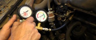
Where can the engine mass be located?
In almost 100% of modern cars, the body is used as a single source of electrical energy.
The car body is like a universal wire with a negative charge for all consumers of electricity. That is why the body is called the painfully familiar term “mass”. Why “painfully familiar”? Yes, because if somewhere the contact with the mass is either poorly secured or oxidized, the inexplicable begins. Let’s take the first example we come across: the sore subject of the first and second Samaras is the blinking of yellow and red headlights, etc.
I have already analyzed this situation in the article: why the headlights do not light up, where I made a “mass”, as the main reason for unstable operation. But the headlights are a small thing compared to the performance of the engine and the electronic engine control system (ECS). In this article we will look at the weak “mass” points on the VAZ 2114 2113 2115 with 1.5l, 1.6l engines.
How to correctly determine the polarity on wires in a car
If the voltage on the car is checked, the course is set to search for a constant one. 20W is the correct setting if you are testing the battery. Therefore, you need to adjust the dial to the desired range/setting and connect the probes to whatever component you want to get a reading for.
You might be interested in this: Connecting resistors
How to check a headlight with a multimeter
Multimeter To check the headlight wiring, you need to find the ground wire.
There are 2-4 wires coming from the connector that connects to the light bulb. Where there are two or three wires, only one of them is ground, while four-wire connectors will have two grounds. To test the wires on the headlight, you need to set the multimeter to resistance. You can place one of the probes on the ground and the other on the negative pole of the car battery.
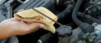
Battery weight
The “minus” on the battery has two branches: a thick wire and a thin one. A thick wire runs from the battery negative to the engine housing. If this contact is not secured properly, then the battery is not fully charged, the starter does not develop full power, and the ECM stalls (since it takes weight from the engine).
On the negative mount of the battery with the engine, you need to check the tightness of the two nuts between which the contact to the engine is attached: first of all, loosen the outer nut and tighten the inner one, and then tighten the outer one.
The second wire from the battery is much thinner and is attached to the body next to the battery itself. This wire is the source for all energy consumers in the car. Here you also need to check the tightening torque of the nut both to the body and to the battery terminal.
PROBLEMS WITH MASS WIRE
The studs for fastening the common wires are often painted along with the body, and therefore the contact on them is not always reliable. In addition, they are fastened at the factory through a nut - first the nut is screwed onto the stud, then the minus is installed, and only then the wires are attracted to ground with another nut. The bottom nut is often poorly tightened, which is why electrical problems arise.
Often, mass-produced studs rust and the integrity of the contact is compromised.
To establish good contact with the common wire, you need to unscrew the top nut, remove the wiring from the stud, tighten the bottom nut all the way and put everything in place.
It is a good idea to place a castle washer between the bottom nut and the body on the stud. The washer will have reliable contact with the body, and electrical problems will not arise due to poor mass.
Castle nut is a good option for connection
ECM weight
For SAMAR with a 1.5 liter engine, the mass for the ECM is taken from the engine housing, from the fastening of the plugs . The plugs are located on the right side of the block head.
For SAMAR with a 1.6 liter engine, but also 1.5 liter engines, which have a new generation ECM (Bosch 7.9.7, January 7.2), the weight of the ECM is taken from a welded stud. The pin is attached to the metal frame of the instrument panel to the floor tunnel (under the ashtray). In practice, it happens that this pin is painted at the factory and is loosely tightened. Therefore, over time it may become loose and at the moment the fan is turned on, there will be a drop in the voltage of the following sensors (which will lead to jumps in speed): DTOZH, TPS, MAF.
How to find out which ECU is on the VAZ 2114 – January 7.2 January 4 Bosch M1.5.4
Today, there are 8 (eight) generations of electronic control units, which differ not only in characteristics, but also in manufacturers. Let's talk about them in a little more detail.
ECU January 7.2 – technical specifications
And so now we move on to the technical characteristics of the most popular ECU January 7.2
The ECU uses a Siemens Infenion C-509 processor (the same as the ECU January 5, VS). The block’s software is a further development of the January 5 software, with improvements and additions (although this is a controversial issue) - for example, an algorithm has been implemented, literally an “anti-shock” function, designed to ensure smoothness when starting and shifting gears.
The ECU is produced (хххх-1411020-82 (32), firmware begins with the letter “I”, for example, I203EK34) and “Avtel” (хххх-1411020-81 (31), firmware begins with the letter “A”, for example, A203EK34) . Both the blocks and the firmware of these blocks are completely interchangeable.
ECUs of series 31 (32) and 81 (82) are hardware compatible from top to bottom, that is, firmware for 8-cl. will work in a 16-cl. ECU, but vice versa - not, because the 8-cl. block “does not have enough” ignition keys. By adding 2 keys and 2 resistors you can “turn” an 8-cell. block of 16 cells. Recommended transistors: BTS2140-1B Infineon / IRGS14C40L IRF / ISL9V3040S3S Fairchild Semiconductor / STGB10NB37LZ STM / NGB8202NT4 ON Semiconductor.
Typical ECU parameters January 7.2 for diagnostics
ECU January-4 - technical specifications
Therefore, during development, the overall and connecting dimensions, as well as the pinout of the connectors, were preserved. Naturally, the ISFI-2S and “January-4” blocks are interchangeable, but are completely different in circuit design and operating algorithms. “January-4” is intended for Russian standards; the oxygen sensor, catalyst and adsorber were excluded from the composition, and a CO adjustment potentiometer was introduced. The family includes control units “January-4” (a very small batch was produced) and “January-4.1” for 8 (2111) and 16 (2112) valve engines.
ECU January 4 second generation of electronic control unit VAZ 2114
The “Kvant” versions are most likely a development series with J4V13N12 firmware in hardware and, accordingly, in software, are incompatible with subsequent serial controllers. That is, the J4V13N12 firmware will not work in “non-quantum” ECUs and vice versa. Photo of KVANT ECU boards and a regular serial controller January 4
ECU diagram January 4
Features of the ECM: without neutralizer, oxygen sensor (lambda probe), with CO potentiometer (manual CO adjustment), toxicity standard R-83.
Bosch M1.5.4 – technical specifications
For Euro-2 toxicity standards, new modifications of block M1.5.4 appear (has an unofficial index “N”, to create an artificial difference) 2111-1411020-60 and 2112-1411020-40, satisfying these standards and incorporating an oxygen sensor, catalytic neutralizer and adsorber.
The brains of the Bosch M1.5.4 ECU
Also, for Russian standards, an ECM was developed for 8-class. engine (2111-1411020-70), which is a modification of the very first ECM 2111-1411020. All modifications, except the very first, use a wideband knock sensor. This unit began to be produced in a new design - a lightweight, leak-proof stamped body with an embossed inscription “MOTRONIC” (popularly “tin can”). Subsequently, ECU 2112-1411020-40 also began to be produced in this design.
Replacing the structure, in my opinion, is completely unjustified - sealed blocks were more reliable. New modifications most likely have differences in the circuit diagram towards simplification, since the detonation channel in them works less correctly, the “tins” “ring” more when using the same software.
Itelma 5.1 - technical characteristics of the VAZ 2114 ECU
VS5.1 uses the same Siemens Infenion C509, 16 MHz processor, but is made on a more modern element base. Modifications 2112-1411020-42 and 2111-1411020-62 are designed for Euro-2 standards and include an oxygen sensor, catalytic converter and adsorber; this family does not provide R-83 standards for 2112 engines. For 2111 and Russia-83 standards Only ECM version VS 5.1 1411020-72 with simultaneous injection is available.
Itelma 5.1 - technical characteristics of the VAZ 2114 ECU
Since September 2003, VAZ has been equipped with a new HARDWARE modification VS5.1, which is incompatible in software and hardware with the “old” one.
- 2111-1411020-72 with firmware V5V13K03 (V5V13L05). This software is incompatible with software and ECUs of earlier versions (V5V13I02, V5V13J02).
- 2111-1411020-62 with firmware V5V03L25. This software is not compatible with earlier versions of software and ECUs (V5V03K22).
- 2112-1411020-42 with firmware V5V05M30. This software is incompatible with software and ECUs of earlier versions (V5V05K17, V5V05L19).
In terms of wiring, the blocks are interchangeable, but only with their own software corresponding to the block.
Bosch M7.9.7 - ECU technical specifications
The January seven had many models depending on the configuration and engine size, so on 1.5 liter eight-valve engines models produced by AVTEL were installed with the bar: 81 and 81h, the same brain from the manufacturer ITELMA had the numbers 82 and 82h. Bosch M7.9.7 was installed on 1.5-liter engines of export models and was marked 80 and 80h on Euro 2 cars and 30 on Euro 3 cars.
ECU weight
A reliable ECU ground is very important for the proper operation of the engine management system and the engine as a whole.
It would seem to be a primitive and reliable design that can serve well for years. But in reality this is far from the case.
It is very difficult to list all the possible problems that can arise due to poor ECU mass, since it can affect anything. But the main problems can be divided into two points:
- Incorrect collection of information from engine control system sensors. Personally, I had to deal with incorrect MAP sensor readings. It gave inflated barometric pressure readings precisely because of the poor weight of the ECU.
- Since almost all modern engine control units are able to adapt to real operating conditions, as a result of incorrect collection of information from sensors, adaptation leads to engine malfunctions. This is why for many, after resetting the adaptations, the engine begins to work much better. But then the problems return as the ECU adapts again. And again this does not happen quite adequately.
What to do if the scanner does not see the VAZ 2114 ECU
So, why doesn’t the scanner see the VAZ 2114 ECU? What should I do so that the device can connect and see the block? Today you can find many different adapters for testing a vehicle on sale.
If you buy an ELM327 Bluetooth, most likely you are trying to connect a low-quality device. Or rather, you could have purchased an adapter with an outdated version of the software.
Car diagnostics using a scanner
So, for what reasons does the device refuse to connect to the block:
- The adapter itself is of poor quality. Problems can be with both the device’s firmware and its hardware. If the main microcircuit is inoperative, it will be impossible to diagnose the engine operation, as well as connect to the computer.
- Bad connection cable. The cable may be broken or inoperative itself.
- The wrong version of the software is installed on the device, as a result of which it will not be possible to achieve synchronization (the author of the video about testing the device is Rus Radarov).
In this case, if you are the owner of a device with the correct firmware version 1.5, where all six of the six protocols are present, but the adapter does not connect to the ECU, there is a way out. You can connect to the unit using initialization strings, which allow the device to adapt to the commands of the machine’s motor control unit. In particular, we are talking about initialization lines for diagnostic utilities HobDrive and Torque for vehicles that use non-standard connection protocols.
Where is the ECU ground located?
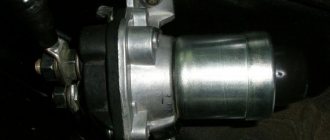
The ECU mass is usually arranged like this. Separate ground wires are removed from the ECU connector and connected to the engine via the starter mounting bolt. Ground wires are usually black
Everything is simple and reliable. But in reality, over time, the voltage begins to drop in this section of the circuit, slowly but surely, disrupting the operation of the system.
Therefore, this unit must be periodically checked and maintained. We will look at how to do this further.
Weight between engine and body
Line “31”, popularly called “ground”, “minus” or “negative circuit”, is very important for a car. And not only for electrical equipment, but also for many other systems, including the engine or automatic transmission.
Almost all cars have a single-wire on-board network system and the role of the “minus” in this circuit is played by the metal parts of the body. This greatly reduces the number of wires and reduces the cost of the car.
It turns out that all participants in this chain have their own connection to the body - instrument panel, headlights, ECU, engine, etc.
Despite the visual integrity of these connections, over time, due to oxidation and corrosion, the contact slowly and imperceptibly deteriorates, which leads to voltage drops when powerful consumers are turned on or disruption of the system.
I would divide the mass connections into main and local. Let's say that the connection of the head light masses is local and if this connection is disrupted, only the head light will suffer. But if the ground contact from the battery to the body is broken, the entire on-board network will suffer, and this may cause problems in the operation of the engine and other important components and assemblies.
ADDITIONAL MASS WIRES
If the weight of the engine with the body is bad, then problems arise:
- The battery may not charge well;
- The starter turns poorly when starting the engine, or may not turn at all, only the solenoid relay will click;
- At full power consumption (high beam headlights on, heater motor running, etc.), the generator may not be charging enough.
When symptoms of poor engine weight appear, there is a way out of the unpleasant situation - in this case, additional weight on the engine will help. You can install an additional wire in different ways, the most important thing is that it reliably connects the car body with the power unit. For example, one end of the wire can be attached to the stud of the upper shock absorber support, and the other to the stud of the intake manifold of the internal combustion engine. It is important that the wire has a large cross-section, preferably no less than that of the bulk itself.
On new machines, problems with mass wires rarely occur. But on older models, the body studs rust. Finding a lack of ground is not so easy, so car owners use the installation of additional wires. So the additional mass on the generator helps eliminate battery charging leakage.
An additional wire is a necessity on used cars
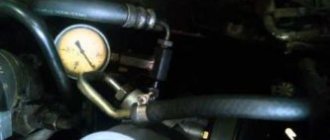
Poor weight causes unstable engine operation. For example, a weak mass with the ECU affects the stability of the engine at idle speed. There is a loss of voltage in the circuit, and when the electric engine cooling fan is turned on, the idle speed drops noticeably, sometimes even to the point of stopping the internal combustion engine. Therefore, contact must be established and a reliable ground must be established. The problem on the new generation VAZ 2113-15 is also solved by installing an additional thick bulk wire (about 2.5 mm²) - it stretches from the negative terminal of the battery to the metal base of the center console in the car interior
Where is the mass located: engine - battery - body
On most cars, the engine-body mass has a primitive appearance and is made of two pieces of cable connected together by crimping on the negative terminal of the battery
This crimp connects two wires. One goes to the engine and is secured with the starter mounting nut...
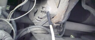
...and the second one on the body in the area of the left wing
It would seem that this is the simplest and most reliable chain that will serve well for years. But this is not at all true and it’s all to blame for the weak points in this design, which do not withstand the test of atmospheric influences.
Checking weight in a car
Transmissions on some vehicle models are equipped with a chassis or protective shield for modules, sensors, and solenoids (relays). You can also test these grounds using your digital multimeter.
Clean, repair or replace the transmission ground as necessary. Remove grease, rust and paint from ground terminals or replace damaged ground straps.
General Voltage Drop Values
Choke cables and other equipment can be damaged when high electrical current cannot find the correct path back to ground.
How to check mass on a car
In fact, only a small group of motorists pay enough attention to this issue. Others begin to think about it when, when the cooling fan or headlights are turned on, the engine speed begins to sag, or when the rear window heating is turned on, the engine begins to tremble, transmitting vibration throughout the body.
But even at this stage, many limit themselves to a banal inspection and tightening the ground connection nuts on the engine and body. Everything is screwed down - that means everything is in order.
Then the car begins to jerk for no apparent reason, idle speed freezes, misfires, security system glitches, and so on, until the starter fails at the most inopportune moment. But even here, many will not go check the masses, but will run to the store for a new starter. After all, the wire to the starter is intact and there is voltage, but it, a radish, does not turn.
Replacing the starter, of course, does not help. As a result, the still-living battery goes into recycling and the situation seems to have improved, but after a couple of days the starter fails again and you begin to believe in brownies and otherworldly forces that have nothing better to do than cause damage to someone else’s car.
But, fortunately, reason wins and the advice of a good man is remembered - to check the masses.
Again, what's so difficult about this? It is necessary to check the resistance from the engine to the body.
Checking grounding in a car
Electronic modules and many electrical components in the engine, transmission and passenger compartment use the body as an electrical ground. This test checks for unwanted resistance at these points, including the secondary ground between the battery and chassis used by some older models. If necessary, consult your vehicle's repair manual.
You should get a voltage drop of 0.2V or less. If the voltage drop is higher, proceed to the next steps.
If you get a reading higher than 0.2 volts, proceed to the next step.
When you get a reading around 0.2V or lower, the unwanted resistance is between this and the previous test point. Check for corrosion, broken or loose wires.
Also, check the voltage drop on the ground circuits that connect the engine to the chassis.
Search, check and replace transfer grounds if necessary.
How to check mass with a multimeter
Disconnect the negative terminal of the battery
We take a multimeter and switch it to resistance measurement mode up to 200 Ohms. We check the resistance of the probes themselves by connecting them together
The resistance of the probes themselves is 2.1 Ohms.
Now we connect one probe to the engine. At least here
And the second probe is to the engine control unit, which, in turn, is screwed to the body
We look at the multimeter readings. So what do we see? But we usually see the same 2.1 Ohm
What happens - the mass resistance of the engine - the body has practically no resistance? Is everything perfect? Is the engine and body weight OK? What is the problem then? Is the starter defective or are otherworldly forces overcoming you?
The whole thing is much simpler. What is a mass chain in the understanding of an ordinary person? This is just a piece of wire that connects the engine to the body. Just a piece of wire! If we connect ohmmeter probes to the ends of this wire, then we will find out its resistance. It will be minimal - it’s just a piece of copper wire. Right? Right.
If we connect the voltmeter probes to the ends of this wire, we will see zero voltage. After all, where will the potential difference come from on a single piece of wire? Right? Right.
Now let's connect our voltmeter to this ground wire on the car. That is, as when measuring resistance, one probe is to the engine, and the second to the body. They are connected by this piece of wire. Right? Right.
We switch the multimeter to the mode for measuring constant voltage up to 2 Volts. We start the engine and look at the device display.
Oops. And we have tension!
How can this be - we are connected to the ends of one wire, and we have voltage.
So I showed off my artistic creativity and painted a picture of what was happening
Red is the ground wire, and blue is the voltmeter
These values on the multimeter display are nothing more than the voltage drop on our ground wire! Even though it looks great and has minimal resistance, it still drops voltage. Moreover, the greater the consumer current in the circuit, the greater the voltage drop on this wire will be, which can reach several volts!
This is the situation. And the mass of the engine and body is not as good as it seemed at first, and problems from it are inevitable.
How to come out of such a situation as a winner?
First, it is necessary to periodically service this section of the chain.
Unscrew the mass on the body
Do the same with the mass on the engine.
But this doesn't always help. The fact is that this chain still has weak points - crimps.
Crimping lugs, crimping on battery terminal
All this oxidizes over time and cannot fully perform its function.
It is necessary to either re-crimp these connections, or it is better to change these wires sometimes.
Here is a video on the topic of engine mass - body
Well, ideally you can lay additional ground wires: Generator - body
Source
How to find leakage current
If the measurements turn out to be disappointing, you will have to look for the “culprit” of high energy consumption. Let's first consider malfunctions of standard components that can lead to high leakage current.
- The diodes on the generator rectifier should not allow current to flow in the opposite direction, but this is only in theory. In practice, they have a small reverse current, about 5-10 mA. Since there are four diodes in the rectifier bridge, we get up to 40 mA. However, over time, semiconductors tend to degrade, the insulation between the layers becomes thinner, and the reverse current can increase to 100-200 mA. In this case, only replacing the rectifier will help.
- The radio has a special mode in which it consumes virtually no power. However, in order for it to enter this mode and not discharge the battery while parked, it must be connected correctly. To do this, the ACC signal input is used, which should be connected to the corresponding output from the ignition switch. The +12 V level appears on this output only when the key is inserted into the lock and turned slightly (ACC position - “accessories”). If there is an ACC signal, the radio is in standby mode and can consume quite a lot of current (up to 200 mA) while being turned off. When the driver removes the key while leaving the car, the ACC signal disappears and the radio goes into sleep mode. If the ACC line on the radio is not connected or is shorted to +12 V power, the device is always in standby mode and consumes a lot of energy.
- Alarms and immobilizers begin to consume too much due to faulty sensors, for example, jammed door switches. Sometimes “appetites grow” due to a failure in the device’s software (firmware). For example, the controller begins to constantly supply voltage to the relay coil. Depends on the specific device, but completely disabling and resetting the device, or reflashing it may help.
- Various switching elements such as relays or transistors can also create increased consumption. In a relay, these may be contacts that are “stuck” from dirt and time. Transistors have a tiny reverse current, but when a semiconductor breaks down, its resistance becomes zero.
In 90% of cases, the problem lies not in the standard equipment of the car, but in non-standard devices connected by the driver himself:
- The same rules for connecting the ACC line apply to the “non-native” radio as to the standard one. Cheap, low-quality radios can ignore this line altogether and remain in normal mode, consuming more power.
- When connecting amplifiers, it is also necessary to follow the correct connection diagram, because they also have a power and energy saving control signal line, which is usually controlled by the radio.
- Just changed or added a security system, and the very next morning the battery was completely discharged? The problem is clearly there.
- In some cars, the cigarette lighter socket does not turn off even when the ignition is turned off. And if any devices are powered through it (for example, the same DVR), then they continue to put a noticeable load on the battery. Don't underestimate the "little box with a camera", some of them have a consumption of 1 A or more.
There are indeed a lot of devices in a modern car, but there is an effective way to search for the “enemy”. It consists of using a distribution box with fuses, which is found in every car. The +12 V bus comes to it from the battery, and from it the wiring goes to all sorts of consumers. The process is as follows:
- We leave the multimeter in the same connected position as when measuring leakage current.
- Find the location of the fuse box.
Fuse boxes are most often located in the engine compartment and in the passenger compartment under the dashboard
- Now we remove each of the fuses one by one, monitoring the readings of the multimeter. If the readings have not changed, put it back in the same place and move on to the next one. A noticeable drop in the device readings indicates that the problem consumer is located on this line.
- There's only one small thing left to do: using the car's electrical diagram from the documentation, we find out what this or that fuse is responsible for, and where the wiring goes from it. There we also find the end devices that were causing the problem.
Have you tried all the fuses, but the current still hasn't changed? Then you should look for a problem in the car’s power circuits, to which the starter, generator and engine ignition system are connected. Their connection point depends on the car. On some models they are located right next to the battery, which is certainly convenient. All that remains is to start turning them all off one by one and don’t forget to monitor the ammeter readings.
It is recommended to check power circuits last
Another option is possible: we found a problem line, but everything is fine with the connected consumers. Understand the wiring itself along this line. The most common situations: the insulation of the wires has melted due to heat or heating of the engine, there is contact with the car body (which is the “ground”, i.e. the minus of the power), dirt or water has gotten into the connecting elements. You need to localize this location and fix the problem, for example, by replacing the wires or cleaning and drying the blocks affected by contamination.
The problem of current leakage in a car cannot be ignored. Any electrical equipment is always a fire hazard, especially in a car, because there are also flammable substances. Turning a blind eye to increased consumption, you will at least have to spend money on a new battery, and the worst that can happen is a fire or even an explosion in the car.
If the article seemed incomprehensible to you, or you do not have sufficient qualifications to work with electrical equipment, it is better to entrust the work to service station professionals.
THIS ARTICLE IS MORE FOR MYSELF, I WANT TO CHECK MY OPEL ASTRA GTC AT MY LEISURE.
If the car is parked for a very long time and is not used, then after the driver turns the key in the ignition, nothing will happen. In the process, the relay may click, perhaps even the starter will come to life. But even if it rotates the crankshaft, it is not enough. All of these are symptoms of the battery being discharged while the car was parked. There is a standard for current leakage in a car. But when the battery is discharged, these indicators are significantly higher than these normal values. Let's look at how you can detect current leakage and fix this fault.
WHY DOES THE BATTERY GO DOWN? During long-term parking, the charge should not go away, but leakage currents must also be taken into account. The battery discharges especially quickly in modern cars. Here, a considerable number of different electronic devices and gadgets are included in the network.
Often in such cases, the rate of current leakage in the car is much higher than permissible. Typical causes include old and poor-quality wiring, as well as wire insulation. Another common cause is improperly connected electronic equipment. This could be an audio system, multimedia, navigator, and so on. The causes of current leakage in a car may be dirty or oxidized contacts. All this significantly drains the battery.
De-energize the board: why do you need a mass switch and can it be installed on a modern car?
Disclaimer. The author is by no means a retrograde and is not trying to “attach a typewriter keyboard to a tablet.” However, the decisions of previous decades, it turns out, under certain conditions, have a right to life.
The electrical equipment of modern cars is full of various “smart” units, which are assigned dozens of comfort and safety functions. However, in some ways the electrics of today’s cars are not far removed from the cars of half a century ago - for example, the voltage in the on-board network is still 12 Volts, and in many cases the lead-acid battery remains the “guardian of life” (not so long ago we explained why they are not changed Whether lithium-ion), the “minus” is located on the body, and the problem of current leakage with a significant increase in the number of consumers has become even more urgent. And today we will find out what a ground switch is, whether it is needed at all in a modern car, and in what cases its use is permissible and even desirable.