High-voltage wires VAZ 2115
Automotive high-voltage (HV) wires play an important role for internal combustion engines, since they help transmit high current from the ignition coil to the spark plugs. The serviceability and efficiency of the wires determines the timeliness and intensity of ignition of the fuel-air mixture, and therefore the correct and uninterrupted operation of the engine. Despite their simplicity, wires have many different “sores” and can cause a lot of troubles to their owner, which in one way or another will affect his nerves and pocket.
Table of contents
Connection Replacement Location
Connection
The order of connecting high-voltage wires must be strictly sequential, since each cylinder of the engine corresponds to a specific socket on the ignition module. Considering that there is a numbering of the sockets on the ignition module body, the risk of confusing anything is minimal.
The procedure for connecting high-voltage wires of the VAZ 2114 injection type depends on the year of manufacture of your car. Fourteen cars before 2004 had 4-pin ignition modules installed, and cars after 2004 had 3-pin coils.
The connection diagram for VAZ 2114 high-voltage wires to the ignition module (until 2004) is as follows:
Connection diagram for VAZ-2114 with ignition coils (after 2004):
In the pictures you can see the numbers of the landing slots. Each number must have a corresponding cylinder connected to it (cylinder numbering is counted from left to right).
To correctly install high-voltage wires on the VAZ 2114, follow the following algorithm of actions:
— Turn off the ignition. Open the hood and remove the power terminals from the battery;
— We remove the old GDPs from the mounting sockets on the module and cylinders;
— We remember the location of the high-voltage wires of the VAZ 2114 and connect new GDPs according to the diagram. Before replacing, it would not be amiss to draw this very diagram by hand on paper so as not to confuse anything;
— We connect power to the battery and, to check whether we did everything correctly, start the engine.
When installing the wiring, do not try to connect individual air intakes to each other with plastic clamps; to do this, you must use the comb holder that comes with them. A thin clamp can easily wear through the insulating coating. Also make sure that the GDP does not bend.
Connecting armored wires on VAZ 2115 and 2113 is carried out in a similar way.
Instructions: replacing the brake master cylinder. br> Vacuum amplifier malfunction, the material is available at the link.
Replacement
How to remove high-voltage wires?
Turn off the ignition. Open the hood. Pull out the wires from the ignition module and from the engine.
How to connect high voltage wires?
The BB wires must be connected in a certain order. Each wire goes to a specific cylinder and to a specific connector in the ignition module (ignition coil). There are markings both on the wires and on the ignition module. But without removing the module, the markings cannot be seen, so see the photo below.
Connection diagram for high-voltage wires:
Cylinder numbering from left to right. Ignition module numbering: first cylinder - lower left compartment of the ignition module
Second cylinder - upper left compartment
The third cylinder is the upper right,
The fourth cylinder is the lower right compartment of the ignition module.
Location
Incorrect installation and location of high-voltage wires can lead to a spark jumping from wire to wire or to ground, which, in turn, can lead to misfires and a decrease in the crankshaft speed when the car is moving at high speed.
Therefore, install the high voltage wires properly as shown in the pictures above.
Examination
EXECUTION ORDER
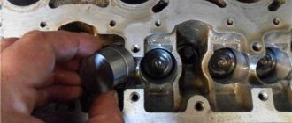
Disconnect the high-voltage wires from the spark plugs and ignition coils. Clean and check the integrity of the insulation of high-voltage wires. Check the internal contact surfaces of high-voltage wires for corrosion or carbon deposits.
Use an ohmmeter to measure the resistance of the high-voltage wires.
| High voltage wires | ||||
| Cylinder | №1 | №2 | №3 | №4 |
| Length, mm | 560 | 440 | 360 | 310 |
| Resistance (BOUGI), Ohm | 2,51–3,76 | 1,97–2,96 | 1,61–2,42 | 1,39–2,08 |
| Resistance (R16AIPS), Ohm | 5,60–11,76 | 4,40–9,24 | 3,60–7,56 | 3,10–6,51 |
The resistance of the high voltage wire should not exceed 10,000 ohms, otherwise replace the wire.
Ignition module VAZ 2115 - check, malfunctions and replacement
We check the ignition module on the injection 16-valve VAZ-2110
To begin with, I would like to note that the ignition module on the VAZ 2115 is a fundamentally new device that is more reliable than what was installed on earlier models of VAZ cars. The essence of the operation of this device is that it produces a high voltage electric current, which is subsequently transmitted to the spark plugs of the vehicle's ignition system.
Operating principle of the ignition module
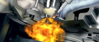
As mentioned earlier, the main task of the ignition module is that it generates a high level of voltage, which is subsequently transmitted to the spark plugs. The generated current undergoes a compression procedure, as a result of which a working spark is supplied to one of the spark plugs of the ignition system, and an “idle” spark is supplied to the second. To be more correct in statements, the working spark is supplied to the first and fourth spark plugs of the vehicle’s ignition system, and the “idle” spark is supplied to the second and third. Thanks to this high-voltage electric current supply system, the spark appears at the right stroke and on the right cylinder, which ensures stable operation of the system.
Video. Checking the ignition module of the VAZ 2115
Power to the VAZ 2115 ignition module is supplied directly from the vehicle’s on-board electrical network. The voltage supplied to the ignition module is twelve volts. At the same time, you should know that the negative wire of the ignition module is attached directly to the vehicle body. Design of the VAZ 2115 ignition module
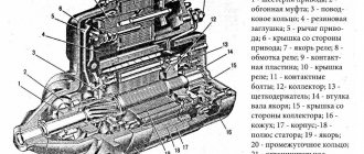
The vehicle ignition module consists of a housing made of plastic, a pair of electronic control units, a pair of high-voltage current transformers, and four outputs for BB-type wires. Dimensions of the VAZ 2115 ignition module: one hundred ten by one hundred seventeen by seventy. The weight of the ignition module is one kilogram, three hundred and twenty grams.
Operating principle of the ignition module
The supply of electric current is carried out using wires of the BB type; the supply of electric current is controlled using a special controller, which makes decisions based on information that comes to it from various sensors of the vehicle. Also, the controller’s tasks include setting the sequence in which the ignition coil operates.
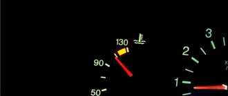
The ignition module can carry out its uninterrupted operation at temperatures from minus forty degrees to plus one hundred and thirty degrees Celsius.
What are the signs that indicate a faulty ignition module?
There are several typical signs that directly indicate problems with the ignition module:
1. Engine idle floats.2. Engine traction periodically disappears for no reason.3. The car picks up engine speed very slowly when accelerating.4. The cylinders stop working in pairs.
Note that the same signs indicate a malfunction of the BB wires and spark plugs of the vehicle’s ignition system, so in the beginning, you should check them, and if everything is fine with them, then replace the ignition module.
Tools you will need:
To replace the ignition module on a VAZ 2115 car, you will need very few tools:
1. Open-end wrenches for seventeen and thirteen.2. Ten socket wrench.3. Hexagon.
Replacing the ignition module on a VAZ 2115 with your own hands
To independently replace the ignition module on a VAZ 2115, you should strictly adhere to a certain sequence of actions, which you can find below:
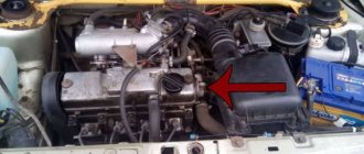
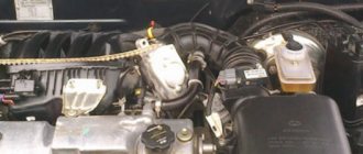
1. First, you must find the ignition module itself in the engine compartment. This can be done by following the high-voltage wires that come from the spark plugs of the ignition system.
2. Next, you must disconnect the negative cable from the battery.
3. Now, you need to remove the block to which the wires are connected from the ignition module.
4. Next, you should disconnect the high-voltage wires.
5. Now, you can unscrew the mounting bolts that secure the ignition module to the engine and remove it.
6. Then all you have to do is mount the new ignition module and assemble the entire structure in reverse order.
Ignition circuit for VAZ-2113, 2114, 2115
The ignition circuit in the VAZ-2114 is almost completely identical to models 2113 and 2115 and includes a coil, wires, switch, module, etc. The main task of the parts is to generate voltage, which enters the spark plugs and causes them to create a spark.
Ignition system diagram
A high-voltage coil ensures ignition of the fuel-air mixture, regardless of whether they are injection or carburetor engines with a sensor. With the advent of contactless power systems, distributors (distributors) are a thing of the past. They were replaced by new schemes from the VAZ-2114, the operating principle of which is based on the logic of standard structures. In older systems, voltage was generated by disconnecting the contacts. In new ones, the signals are supplied by a control unit, which collects signals coming from sensors on the motor, forms them into a control pulse and sends them to the ignition circuit. High voltage is generated by two coils and a two-channel electronic switch.
The system includes:
- Hall Sensor.
Hall sensor location
- Module.
Ignition module
- On relay, as well as switch.
- Electronic switch.
Electronic switch location
- High voltage wires.
High voltage wires
Contactless connection is ensured by a low-voltage power supply connector. High-voltage wires are connected directly to the spark plugs.
If there are problems in the unit, you must first check the spark plugs.
To do this you need:
- Disconnect the armor wire ends.
Disconnecting the tips
- Unscrew the spark plugs with a key number 17. Based on their condition, the specialist will determine the location of the problem.
Unscrew the spark plugs with a 17 key
The carburetor is checked last. In fact, this part can only be replaced.
How to check the ignition module of a VAZ-2114
Interruptions and jerking when driving, a shaking engine, difficult starting or even engine failure are the main signs of failure of the ignition module.
The difficulty of diagnosing on your own is that the module combines several devices at once , and it itself is made in a single housing, and there is no way to check each device separately. At least with your bare hands. Nevertheless, something can be done in order to, if not repair, then at least know for sure the cause of the malfunction.
Checking the quality of contacts
First of all, without dismantling anything, it is worth checking the quality of contact on all blocks of the low voltage circuit , as well as establishing the presence of contact on the high voltage wires.
Checking the presence of power on the ignition module
Checking the voltage on the ignition module pads
In order to know that it is the module that is faulty, let’s check whether power is supplied to it. To do this, we find the connector in the block, and there we look for a contact marked with the letter A. To control the power supply to the module, take a multimeter, set it to measure alternating current up to 20 V , install one probe (negative) to engine ground and turn on the ignition. We install the second probe on terminal A on the block. If the electrical equipment is in good working order, the multimeter will show 12 V, which means that power is supplied to the module, we look further for the cause of the malfunction.
Video “The principle of operation of internal combustion engines”
This instructional video explains how the combustion system works.
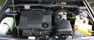
Many motorists, especially beginners who have just purchased a VAZ-2114, have wondered how the 8-valve injection engine that is installed on this car works. This article will discuss the design of the motor, its main characteristics, as well as dismantling and repair features. This information will be very useful for beginners and those who do not know how the main power unit works.
Video about the VAZ-2114 engine
Video review of the VAZ-2114 engine operation, features and characteristics.
How to replace the ignition module on a VAZ 2113-VAZ 2115?
Removal: 1) First disconnect the “-” terminal from the battery, thereby de-energizing it. (How to remove the minus terminal in order to de-energize the battery, see the article: “Replacing the battery”).
2) Then find the location of the ignition module in the engine, and after finding it, disconnect the four high-voltage wires that are connected to it.
3) Next, disconnect the wire block by squeezing the retaining clip that secures it to the module.
4) Next, remove the three nuts that secure this module to the bracket.
Note! To make it easier for you to visually determine, look at the photo below, which shows the places where three nuts secure the module to the bracket!
5) Then remove the module from the three long pins that are present on the bracket.
Installation: The ignition module is installed in the reverse order of removal, but when installing it back, you must know two things:
1. After the ignition module is installed, look at its surface, you see the numbers shown there: 1, 2, 3, 4. So, these numbers indicate the numbers of the corresponding cylinders.
2. Have you noticed that the same numbers are present at the tips of the high-voltage wires: 1, 2, 3, 4. All this was done to make it easier for you to determine which of the high-voltage wires should be connected to the module where.
Note! When reinstalling the module, connect all high-voltage wires strictly by numbers, for example: “the first wire - to the first terminal”, “the second wire - to the second terminal”, etc.
Checking the ignition module for functionality:
To check the module, you will need a “high-voltage arrester”, which can be purchased at a car store for a price in the region of 900-1500 rubles. Using this spark gap, you can check for serviceability: the ignition module, the ignition coil, and the high-voltage wires themselves for the presence of sparking.
Note! The video clearly shows that the ignition module is working properly, because when all the wires are connected to it one by one, a spark constantly appears on the spark gap, but the last check shows that the spark breaks off a little, but still the module performs well and does not need to be replaced !
Important! When working with the ignition module, be careful, and under no circumstances carry out any actions with it without de-energizing the battery!
Firing order
The cylinders in a car do not work chaotically, because for stable operation of the engine and alternate execution of all four strokes, their strict synchronization is required.
So there is a special order of operation of the cylinders of the VAZ 2114, thanks to which each of them at one point in time performs any of 4 strokes, namely:
- Injection of a mixture of fuel and air that fills the entire volume of the cylinder.
- Compression of the working mixture due to the upward movement of the piston.
- The combustion of the working mixture and the expansion of the resulting gases pushes the piston in the opposite direction, thereby driving the connecting rod and crankshaft.
- The release of exhaust gases from the cylinder with their further discharge into the exhaust system.
Ignition order of the VAZ 2114
It is worth noting that on cars of different brands and even models, the engine may have a different operating circuit, but the operating order of the cylinders of the VAZ 2114 injector always looks like this: 1-3-4-2. According to this diagram, the high-voltage wires should be connected.
For greater convenience, the cylinders are numbered accordingly, starting from the front cover of the engine.
How to check the ignition module on a VAZ 2114
An ignition module is needed in a car to produce high voltage current, which then ignites the spark plugs. On different VAZ vehicles, a separate or block ignition module can be installed. In separate type modules, there is a separate coil for each cylinder. In block modules, one coil is used for two or all cylinders at once. It should be noted that the block ignition module is much easier to remove, check and install back, compared to a separate one.
The VAZ 2114 is now available with a block ignition module; its coil design includes: a core, a winding, high voltage wires and low voltage terminals.
How does a malfunction of the ignition module manifest itself:
Note. Some drivers believe that high-voltage wires and the ignition module are completely different things, and if the wires become faulty, the module will not be affected. This is mistake. If the wires are damaged, the spark may not fire accurately, which can result in the ignition module burning out altogether.
The easiest way to check the ignition module is to install a similar, working ignition module instead of your own. If this is not possible, then you can get by with a multitester or a regular 12-volt light bulb (“control”).
Checking the serviceability of the ignition module using a multitester
Checking the health of the winding
Set the multitester to ohmmeter mode to measure the resistance between the terminals of the secondary winding. Install the probes on the leads to the first and fourth cylinders, then to the second and third (see video below). Usually the tester shows a result close to 5.4 kOhm (plus or minus 0.1 kOhm). The main thing is that the resistance between paired terminals is approximately the same. If the difference exceeds 100 Ohms, then this is evidence of failure of the secondary winding.
Solution to the problem: replacing the ignition module.
Checking the serviceability of high-voltage wires
You need to “ring” the wire block. Set the multitester to voltmeter mode, disconnect the wire block from the ignition module. Place one probe on contact A, the second on engine ground. Have someone start the engine (or turn the starter), and you note the display readings for yourself. Normally, the voltage should be around 12 Volts. Do the same manipulation with the other contact.
If there is no voltage at all, then you need to check the fuse: it may have blown. There are three fuses on the VAZ 2114 electronic control unit. The third one from the top, rated 7.5 A, is the fuse for the ignition module.
There may be no electric current not only due to a blown fuse, but also due to oxidation or broken wires or loose contacts.
Video: How to check the ignition module
Checking the serviceability of the ignition module using a “control”
If you don’t have a multitester at hand, a 12 V test light will help you check the ignition module. Connect one wire of the light bulb to the contact of block A, the other should be shorted to the engine body. Now let someone start the engine (or turn the starter), and you look at the light bulb - it should flicker. Do the same manipulation with the other contact.
How to remove the ignition coil of a VAZ 2114
1. Disconnect the negative terminal from the battery.
2. Remove the tips from the spark plugs.
3. Release the latch and disconnect the low-voltage wire block from the coil.
4. Unscrew the bracket mounting bolts from the gearbox and the lower mounting bolt from the cylinder block.
5. Remove the coil together with the bracket.
6. Disconnect the high-voltage wires from the coil.
7. Unscrew the bolts securing the coil to the bracket.
On the coil, on each terminal there is a mark indicating which wire goes to which cylinder. There are also marks on the high-voltage wires. When installing the ignition module back, you need to take these marks into account. When changing a coil, the new coil must have the same markings.
Video: How to remove the ignition coil of a VAZ 21114
2115 IGNITION MODULE DIAGRAM
The circuit diagram and connection diagram of this electronic device is presented below.
The ignition module installed on the Lada Samara is extremely resistant to both low and high temperatures. Operating temperature range: -400/+1300C.
The only negative point in the operation of this electronic device is its complete inability to repair. However, even a novice car enthusiast can replace it on his own.
Experts consider the most common malfunctions of the Samara ignition module to be:
How to check the ignition module of a VAZ 2115
The correct operation of the VAZ 2115 ignition module determines not only the normal start of the engine, but also the stability of its operation in all modes. To fully check the serviceability of this element of the ignition system, you will need simple laboratory equipment. How to check the ignition module of a VAZ 2115 - preliminary results can be achieved in “field” conditions.
How to check the ignition module of a VAZ 2115
This electrical device creates high (up to 30,000 V) voltage, which is then transmitted to the spark plugs. Some car owners call this device a coil, although this is not entirely correct, since two coils are included in the module.
The 1st coil is responsible for the operation of cylinders 1 and 4, the 2nd for the operation of cylinders 2 and 3. In addition, the module contains 2 switches. These elements are located inside one plastic case. It is not difficult to find this module under the hood of the car; high-voltage wires go to it.
Among the main signs of a malfunctioning ignition module are loss of power, dips during a sharp increase in speed, unstable idle speed, and inoperative cylinders (1 and 4 or 2 and 3). These problems can be caused by a malfunction of the ignition module if the DS, MAF and IAC sensors are working properly.
Checking the VAZ 2115 module
Before you start testing the device, you must make sure that the wire blocks connected to it are in good condition. For these purposes you will need a tester. You should disconnect the block, then touch the “A” contact with one of the probes of the device, and the second to ground. After this, turn on the ignition and look at the tester readings.
The voltage should be 12 V. If it is missing, it can be argued that the fuse is faulty. At the next stage of checking the block, you will need a test light, which should be connected between the “A” and “B” contacts. Ask your assistant to turn the starter, and the light should blink. Otherwise, the wire going to the “A” contact may have broken. The same should be done with the “B” contact. The easiest way to check the functionality of the module is to replace it with a working one. However, there are also nuances here. Ignition modules were installed on the very first Samaras. On later modifications, an ignition coil was installed, but the switch was part of the ECU, and therefore there was no separate module. This must be taken into account if you are going to use a donor car. Another option for checking the ignition module of a VAZ 2115 is to measure the resistance. To do this, you need to touch the tester probes to the module output where the high-voltage wires are connected. Between the contacts going to cylinders 1 and 4 or 2 and 3, the resistance value will be 5.4 kOhm.
If the resistance indicator is normal, but the malfunction remains the same, use the method of “shaking” the module: lightly knocking on the device with the engine running. With changes in its operation, one can judge that there is poor contact between the elements located inside the ignition module.
We told you how to check the ignition module of a VAZ 2115, but it’s better not to fool your head and drop by the nearest car service center!
Did you like the article? Share with your friends on social networks!
HOW TO CHECK THE IGNITION MODULE
The ignition module is one of the main elements of the ignition system for the combustible mixture in the cylinders...
- Unstable operation of the power plant when accelerating the vehicle.
- Decrease in engine power.
- “Intermittent” idle speed.
- Malfunction of paired (1/4 – 2/3) engine cylinders.
Attention! The detection of the above malfunctions is not final evidence of failure of the ignition module, since similar symptoms are possible due to malfunctions of the spark plugs and unreliable connection of high-voltage wires.
VAZ 2115 ignition module, description and malfunctions
The module's task is to generate high-voltage pulses on the engine spark plugs. As a result of compression of the air-fuel mixture, one spark plug is supplied with a working spark, and the second spark is supplied with an idle spark (exhaust stroke).
The “working” spark plug is connected to the first and fourth cylinders of the engine, and the “idle” spark plug is connected to the second and third. Thanks to this connection, the resulting spark synchronously jumps through the cylinders of the car.
What the module consists of, or so to speak, the composition of the device - two electronic control units, two high-voltage transformers, four outputs for high-voltage wires and a small plastic case. The weight of the device is no more than 1.32 kg, dimensions 110x117x70 mm.
The module is connected to the spark plugs using high-voltage wires that supply sparks to the spark plugs.
Control is carried out using a controller that processes all data on the operation of the vehicle, reading information from sensors, and establishing the sequence by which the ignition coils in the module are fired.
To ensure high accuracy of ignition control, the controller uses information about the crankshaft rotation speed; about the load on the engine /air consumption/; about the temperature of the liquid that is used to cool the engine of your iron horse; about the position of the crankshaft and the presence of detonation.
The ignition module remains operational at air temperatures from -40 degrees Celsius to + 130.
If there is a malfunction, the device cannot be disassembled or repaired. Such a module must be replaced, which is easy to do on your own without involving specialists.
Possible malfunctions of the ignition module:
- Power reduction;
- Unstable engine operation during acceleration;
- Paired cylinders /1-4 and 2-3/ do not work;
- Intermittent idle.
If such malfunctions are detected, you must first check the reliability of the connection of the high-voltage wires and the serviceability of the spark plugs.
With the engine running, the check must be carried out, observing safety precautions: either work with rubber gloves, or the handles of the pliers must be insulated.
If everything works fine, then the ignition module should be replaced. It is located under the hood of the car and its location is easy to find by thickened high-voltage wires.
You will need tools: socket wrench “10” /head/, wrenches “13” and “17”, hexagon.
The procedure for removing a faulty ignition module:
- Disconnect the negative terminal from the battery;
- Pull out the wire block from the ignition module;
- Disconnect the high-voltage wires;
- Unscrew the fastenings to the engine;
- Pull out the ignition module by unscrewing it from the holder with a hexagon.
In order to install a new ignition module, you must first insert the high voltage wires, following the prompts on the module body.
On the terminals of the wires themselves there are also designations of the engine cylinder numbers. Then you should carry out the described steps strictly in reverse order. After starting the engine, you need to check that the ignition module is installed correctly.
Owners of VAZ 2109 - 2115 cars who cannot independently monitor the technical condition of their cars can, of course, be serviced at a service station, where they will be offered diagnostics and high-quality repairs of the car’s engine. Here, as they say, to each his own.
Signs of faulty wires
There can be many different signs of faulty high-voltage wires, but there are several signs that, once detected, require the wires to be replaced.
Signs:
- The car jerks when you press the gas pedal. This is due to the fact that with a higher load the engine needs a large amount of fuel and its timely combustion, but since the wires are not able to give a spark at the right time, the car begins to twitch.
- When starting the car, one or more cylinders may not fire. This is due to the fact that when a spark is transmitted, it breaks through to the housing due to breakdown of the insulation.
To check the wires in more detail, you need to remove them from the car and carefully inspect them.
The wires should not contain:
- Gusts;
- Zadirov;
- Insulation breakdowns;
- Cracks in the plastic case;
Rupture of the protective cap of the GDP If such problems are found on the wires of your car, then they need to be replaced.
Possible ignition coil malfunctions
If the coil malfunctions, quite unpleasant consequences will appear in the operation of the car: engine power will decrease, its operation will become less stable (especially during wet weather), fuel consumption may increase, and jerks and dips will begin to occur when you press the gas pedal. If there is a serious breakdown in the ignition coil, the car will not start at all.
There are many reasons for the failure of the ignition coil, but all of them can be classified into the following groups:
The most common reason is mechanical defects . These include banal scratches and wear and tear of materials. If the coil is oil-filled, oil may leak through the seals and onto the insulation, causing product failure.
Problems with contact connection . This problem can be classified as seasonal, since damage often depends on weather conditions. During high temperatures, excess moisture may get under the hood (during rainy weather). In winter, road traffic from icy conditions may well get into the engine compartment.
Overheating . Quite a common problem among custom reels. In the vast majority of cases, overheating occurs due to the use of low-quality coolant.
Vibration . Typically, vibrations start from the cylinder head (cylinder head) and, like overheating, are more common in the operation of individual coils. The occurrence of too strong and frequent vibrations is directly related to the operation of the engine - it must function without detonation. In addition, the health of the engine mounts affects the amplitude and number of vibrations.
Connection diagram for high voltage wires
Connecting new or removed old wires must be done strictly according to a specific scheme. Otherwise, the spark will not coincide with the compression stroke in the cylinder block.
In other words, when the fuel mixture is ready to ignite in the cylinder, a spark is required to ignite it. If the connection is incorrect, the spark will not appear at the required moment and ignition will not occur, which will make starting the engine impossible.
Scheme
The order and counting of cylinders in VAZ engines starts from the timing belt drive, from left to right, that is, the first cylinder will be at the timing belt, and the 4th at the oil filler neck.
Most often, the cylinder number is indicated on the ignition module, but there are cases when there are no designations on the module, then it is necessary to connect the cylinders according to the diagram shown below.
- The first cylinder is connected to the lower left contact on the MH;
- The second cylinder is connected to the upper left contact on the MH;
- The third cylinder is connected to the upper right contact on the MH;
- The fourth cylinder is connected to the lower right contact on the MH;
How to check the ignition module of a VAZ-2114
Interruptions and jerking when driving, a shaking engine, difficult starting or even engine failure are the main signs of failure of the ignition module.
The difficulty of diagnosing on your own is that the module combines several devices at once , and it itself is made in a single housing, and there is no way to check each device separately. At least with your bare hands. Nevertheless, something can be done in order to, if not repair, then at least know for sure the cause of the malfunction.
Checking the quality of contacts
First of all, without dismantling anything, it is worth checking the quality of contact on all blocks of the low voltage circuit , as well as establishing the presence of contact on the high voltage wires.
Checking the presence of power on the ignition module
Checking the voltage on the ignition module pads
In order to know that it is the module that is faulty, let’s check whether power is supplied to it. To do this, we find the connector in the block, and there we look for a contact marked with the letter A. To control the power supply to the module, take a multimeter, set it to measure alternating current up to 20 V , install one probe (negative) to engine ground and turn on the ignition. We install the second probe on terminal A on the block. If the electrical equipment is in good working order, the multimeter will show 12 V, which means that power is supplied to the module, we look further for the cause of the malfunction.
How to choose high-voltage wires
When choosing new high-voltage wires for your car, you should be guided by their two most important parameters - resistance and breakdown voltage. So, the less resistance the armor wire core has, the better it will transmit the impulse from the module to the spark plugs, and the easier it will be to ignite.
Selection of armored wires for VAZ 2114
As for the second factor, this is the maximum voltage value, above which there is a risk of insulation breakdown, which can result in a number of unpleasant consequences. In addition, when choosing wires, you should pay attention to secondary indicators, for example, insulation resistance to cold, etc.
Checking the armored wires of the VAZ 2114
According to survey results, most car enthusiasts prefer high-voltage wires from Tesla - they have good performance, reliability, and are also resistant to cold and caustic substances.
How to check the malfunction of the VAZ 2114 ignition module on your own?
The main symptoms of a malfunction in the VAZ-2114 ignition module
The easiest way to check the device without removing it is to diagnose it at the moment the power unit is tripped. When the motor begins to operate unstably, it is necessary to disconnect the connector elements from each component of the module one by one. If the connector is disconnected from a functioning device, the operation of the engine will change. Dips will appear, and the unstable operation of the unit will increase. When the non-working element of the MH is disconnected, the motor will operate in the same way.
There is another simple diagnostic method, its principle is as follows:
- You will need an assistant to check. The spark plug is removed from the seat. The high-voltage cable is disconnected from the device.
- Then the disconnected wire is connected to a spark plug, which is applied to the body of the power unit.
- The machine motor is starting, you need to make sure that a spark hits the spark plug. If it passes, a blue light will appear between the device and the surface of the power unit, its formation is accompanied by a crackling sound. If there is no spark, then the spark plugs, high-voltage cable and module must be diagnosed.
In the absence of special equipment, diagnostics of the MH can be performed using a control light indicator designed for 12 volts. One conductor from the lamp is connected to the pin of connector A, and the second is connected to ground for grounding. An assistant must start the power unit or rotate the starter mechanism. If the light flickers when performing these steps, then the device is working. Similar actions must be done with another contact.
The channel “Diary of an Auto Electrician” spoke about self-diagnosis of ignition modules, as well as other elements of the system.
Checking the ignition unit with a multimeter
Diagnostics is carried out in the following order:
- The car engine is started.
- The tester switch must be set to DC measurement mode, the limit should be up to tens of volts.
- One of the contacts of the multimeter is connected to connector D on the coil, and the other goes to ground. You can use a car body or a cylinder block as a mass. If there is power, the diagnostic tool display will show 12 volts.
- Then the tester switches to the ohmmeter operating mode, the range of values is up to tens of ohms.
- One contact of the diagnostic tool is connected to output C, and the second goes to ground. If the device is operational, the test will show a value of less than 1 Ohm.
- At the next stage, the tester must be switched to voltmeter mode. The range of values is up to tens of volts.
- One of the contacts goes to the output marked B, and the second is connected to ground.
- If the diagnostics show that the voltage is less than 0.3 volts, then the device is working. This indicates a clear signal passage from the Hall controller. Finally, you can perform a similar test, only with connector A. The results should be identical.
Direct check of secondary coils for breakdown
To diagnose secondary elements of the MH for breakdown, you will also need a tester:
- All connected conductors must be disconnected from the device connectors.
- Diagnostic equipment is set to ohmmeter mode, the range of values is up to tens of ohms.
- The contact probes of the tester must be connected in turn to the paired connectors of the module. For example, in the second and third, as well as in the first and fourth.
- If the diagnostics showed the same results, then all windings are operational. The resistance parameter should be about 5.4 kOhm. If the values obtained are higher, this indicates an internal break in the device. With lower parameters, we can conclude that there is a breakdown.
Igor Belov shared effective options for diagnosing MH in garage conditions.
https://youtube.com/watch?v=4wHGBUx6x3M
Cons and pros
Depending on which 2114 engine is used, the owner’s risks differ:
- 2111, 21183, 21114 and 21124 – do not bend the valve if the timing belt breaks;
- 21126 – valve bending due to insufficient groove.
The main disadvantage of the latest 16 valve versions is the lighter crank mechanism:
- the engine is adjusted to Euro-4 standards;
- to reduce weight, the length of the piston skirt is reduced;
- Accordingly, the width of the oil scraper and compression rings decreases;
- The resource of the internal combustion engine is sharply reduced.
Grooves in the pistons so that the valves do not bend if the belt breaks
For example, in Japan, manufacturers abandoned Euro-4 standards, considering that the reliability and high service life of the motor are more important for the consumer.
The drive power increased from 77 horsepower to 81 hp, then 82 hp, 89 hp, and 98 hp. In models with hydraulic compensators, periodic adjustment of this unit is not required, however, the quality of the oil in the system must be high for normal operation of the pushers.
Should high-voltage wires be replaced and when?
No matter how well the armored wires are made, they also have a limited service life. According to current regulations, they must be replaced after every 30,000 km traveled. In practice, many motorists ignore this rule, continuing to travel with wires that have already outlived their useful life.
Such inattention can cause a whole host of problems, including:
- poor ignition;
- overclocking problems;
- engine tripping;
- inability to start the car.
Replacement of armored wires of VAZ 2114
All these troubles are caused by one single factor - an increase in the electrical resistance of the core of high-voltage wires, as a result of which it becomes “more difficult” for the impulse from the coil to reach its destination.
You can check whether you can still drive with the old wires or not - at home.
To do this you need:
- Turn off the ignition.
- Remove one of the armored wires.
- Measure its resistance using a megohmmeter or multimeter in the appropriate mode.
- If the resistance turns out to be equal to or close to the figure indicated on the wire insulation, then it is in good condition, but if it turns out to be greater, then the wire should be replaced.
- Repeat this operation on the remaining three wires.
It should be remembered that if only one of the wires is faulty, then all four should still be replaced.
Also, do not forget about the cleanliness of the contacts of high-voltage wires - they can also cause ignition problems. If oxides are noticeable on the metal tip, they should be cleaned with fine sandpaper or a cloth moistened with kerosene. By following these simple rules for caring for armored wires and replacing them, you can almost completely avoid troubles associated with the ignition system.
Replacing the ignition module yourself
Coolant temperature sensor: symptoms of malfunction, purpose, check
So, first of all, we are looking for a module (for those who don’t know). The PVNs from the spark plugs go to it.
- Remove the negative terminal from the battery
- Disconnect the wire block from the module
- Disconnect the PVN
- Unscrew the module itself and remove it
- Now install the new module and reassemble in reverse order.
When installing, do not confuse the position of the PVN on the reel.
Helpful note! If you are installing a new coil and old wires, pay attention to them. If there are yellow stripes at the tips of the spark plugs and wires, then the wires need to be replaced
After replacing the module, you need to check its operation. We start the engine and enjoy the work done.
In the article brought to your attention, we will pay attention to an electronic device called the ignition module of the VAZ 2115 car. Or, more precisely, its description, circuit diagram and performance check
This module consists of two high-voltage transformers and two control units (electronic), enclosed in a durable plastic case with four outputs of high-voltage wires. Electronic control units are also commonly called ignition coils, and one of them - “working” - is connected to the spark plugs of the first and fourth cylinders of the power unit, the other - “idle” - with the spark plugs of the second and third.
The VAZ 2115 ignition module is controlled by a controller whose operating functions include processing data received from vehicle system sensors: coolant temperature, rotation speed and position of the crankshaft, air flow, presence of detonation, etc.
The circuit diagram and connection diagram of this electronic device is presented below.
The only negative point in the operation of this electronic device is its complete inability to repair. However, even a novice car enthusiast can replace it on his own.
- Unstable operation of the power plant when accelerating the vehicle.
Decrease in engine power.
“Intermittent” idle speed.
Malfunction of paired (1/4 - 2/3) engine cylinders.
Numbering of cylinders in different types of internal combustion engines
As for the standards for numbering combustion chambers, there are none. The way they are numbered in the internal combustion engine is influenced by the following factors:
- Type of drive;
- ICE type, block layout;
- Transverse or longitudinal arrangement of the unit under the hood;
- Side of rotation.
On standard front-wheel drive cars with a transversely mounted engine, the numbering begins on the timing side. So, near the timing belt there is the first cylinder and then all the others. The latter is located near the checkpoint.
Examples
In multi-cylinder V-twin engines, the first cylinder is located in the bank on the driver's side.
In American-made engines, the combustion chambers and their numbering may differ and defy logic.
So, for in-line fours and sixes, the first cylinder may be near the radiator, while on all other models the numbering begins towards the interior. If the numbering is reversed, then the cylinder closest to the passenger compartment is considered first.
Note: How to remove a hernia on a car wheel and why it is dangerous
The French are very original and use two methods of numbering the combustion chambers of internal combustion engines.
- On inline fours, the numbering starts from the flywheel.
- If it is a V-shaped six, then the row closest to the radiator is the first three cylinders, and the row closer to the passenger compartment is the last three.
Legend
For ease of maintenance and installation, the electrical wires in the diagrams are made in different colors, identically laid in the car, so that their purpose can be visually determined.
For brevity, colors are indicated by the first letters of the name:
- Blue – “G”;
- Brown – “K”;
- Gray – “C”;
- White – “B”;
- Orange – “O”;
- Yellow – “F”;
- Black – “H”;
- Green – “Z”;
- Pink - "R".
Thanks to the colors, it is easy to determine whether the rein belongs to a particular chain
For reference: the red wire is traditionally used to supply power from the positive terminal of the generator or battery. Therefore, in all diagrams contained in the factory instructions, it is designated by the letter “P”.
The article Wiring diagram for VAZ 21074 injector: understanding the intricacies will also be useful.
HOW OFTEN SHOULD I CHANGE GDP?
According to the recommendations of Avto-VAZ, replacement of high-voltage wires of the VAZ 2114 should be done every 30 thousand kilometers. In practice, motorists rarely comply with these replacement deadlines, since if the wires do not have any mechanical damage, they can travel about 100-150 thousand km.
When the service life is exceeded, the internal resistance of the GDP increases, which negatively affects the transmission of the electrical impulse. This leads to problems with ignition and acceleration dynamics, since when the supply of current to the spark plugs is delayed, the normal engine operating cycle is disrupted.
Change the wires every 25-30 thousand km and everything will be fine