Many motorists, especially beginners who have just purchased a VAZ-2114, have wondered how the 8-valve injection engine that is installed on this car works. This article will discuss the design of the motor, its main characteristics, as well as dismantling and repair features. This information will be very useful for beginners and those who do not know how the main power unit works.
Video about the VAZ-2114 engine
Video review of the VAZ-2114 engine operation, features and characteristics.
Engine design features
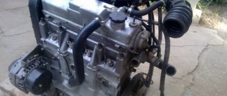
Cars of the LADA SAMARA-2 family are equipped with an engine mod.
2111 - gasoline, four-stroke, four-cylinder, in-line, with a fuel injection system, with a camshaft located in the cylinder head. It is based on the mod engine. 21083. Engine cylinder operating order: 1–3–4–2. The engine is specifically designed for transverse mounting in a front-wheel drive vehicle. The layout and main dimensions of the engine are chosen so that it, together with the gearbox, can be placed transversely in the engine compartment between the body mudguards.
The power unit - an engine with a gearbox and clutch - is mounted in the engine compartment of the car on three rubber-metal supports.
4.1. Longitudinal section of a VAZ-2111 engine
4.2. Cross section of a VAZ-2111 engine
The cylinder block is cast from special high-strength cast iron, which gives the engine structure rigidity and strength. The cylinders are made integral with the block. At the bottom of the cylinder block there are five main bearing supports with removable caps. The main bearing caps are bolted to the cylinder block. The holes for the bearings are machined together with the covers, so the covers are not interchangeable and are marked with marks on the outer surface to distinguish them. The middle support has two sockets for thrust half-rings that hold the crankshaft from axial movements. A steel-aluminum half-ring is installed in front of the main bearing cap, and a cermet half-ring is installed at the rear so that the grooves on the half-rings face the crankshaft. The main and connecting rod bearing shells are thin-walled steel-aluminum. The upper main bearings of the first, second, fourth and fifth supports are with grooves on the inner surface, the lower main bearings and the upper bearing of the third bearing are without grooves. The inner surface of the connecting rod bearings is smooth, without grooves.
The crankshaft is made of high-strength cast iron and has five main and four connecting rod journals. To reduce vibrations, eight counterweights located on the crankshaft are used. To supply oil from the main journals of the crankshaft to the connecting rods, oil channels are drilled in the crankshaft and closed with plugs. In addition to supplying oil to the crankpins of the crankshaft, these channels also serve to clean the oil. Centrifugal force forces solid particles and resins that are not captured by the oil filter element to be thrown towards the plugs.
4.4. Camshaft drive diagram:
1 – crankshaft toothed pulley; 2 – toothed pulley of the coolant pump; 3 – tension roller; 4 – rear protective cover; 5 – camshaft toothed pulley; 6 – toothed belt; 7 – tension roller axis; A – installation ledge on the rear protective cover; B – mark on the camshaft pulley; C – mark on the oil pump cover; D – mark on the crankshaft pulley
At the front end of the crankshaft there is a drive gear of the oil pump, and on the segment key there is a toothed pulley 1 (see Fig. 4.4) to drive the camshaft and water pump. In addition, a generator drive pulley or damper is installed at the front end of the shaft. A flywheel is attached to the rear end of the crankshaft with six bolts through a common washer. It is cast from cast iron and has a pressed steel ring gear designed to start the engine with a starter. The connecting rods are steel, I-section, machined together with the covers. The cylinder number is marked on the connecting rod cap and the connecting rod itself. A steel-bronze bushing is pressed into the upper head of the connecting rod. The piston pin is steel, tubular section, floating type. It is secured against longitudinal movement by two retaining spring rings located in the grooves of the piston boss. The piston is made of aluminum alloy. On the bottom of the piston there is a recess for the combustion chamber and two recesses for the valves. The piston skirt is conical in longitudinal section and oval in cross section. In the upper part of the piston there are three grooves machined for piston rings. There are drillings in the groove of the oil scraper ring that serve to drain the oil collected by the ring from the cylinder walls into the piston. The piston rings are located in the grooves of the piston. The two upper rings are compression. They prevent gases from breaking through into the engine crankcase and help remove heat from the piston to the cylinder. The lower ring is an oil scraper ring.
4.3. Valve drive mechanism:
1 – cylinder head; 2 – valve; 3 – pusher; 4 – camshaft bearing housing; 5 – camshaft; 6 – adjusting washer; 7 – oil deflector cap; A – gap between the cam and the adjusting washer
Cylinder head 1 (Fig. 4.3), common to all engine cylinders, is made of aluminum alloy. The head is centered on the cylinder block by two bushings and secured with bolts. At the bottom of the head, channels are cast through which liquid circulates, cooling the combustion chambers. In the upper part of the head there is a camshaft 5, which rotates in supports made in the upper part of the block head and two bearing housings 4, secured with nuts on studs screwed into the block head. The camshaft is cast from cast iron. To reduce wear, the working surfaces of the cams and the surface under the oil seal are heat-treated - bleached. The camshaft cams operate the valves 2 through pushers 3. Steel adjusting washers 6 are installed in the upper part of the pushers; by selecting these washers, the clearances in the valve drive are adjusted.
The camshaft is driven from the crankshaft toothed pulley 1 by a rubber toothed belt 6 through the toothed pulley 5 (Fig. 4.4). The belt tension is adjusted by tension roller 3. A metal-reinforced gasket made of non-shrinking material is installed between the head and the cylinder block.
The cylinder head is equipped with eight valves - two valves per cylinder (one intake and one exhaust). The valves close under the action of two springs. The lower ends of the spring rest on the support washer, and the upper plate of the springs is held by two crackers in the valve groove. The outer surface of the valve cotters has the shape of a truncated cone, and on the inner surface there are three thrust protrusions that fit into the corresponding grooves of the valve stem.
The guide bushings and valve seats are pressed into the cylinder head. Lubrication channels are cut on the inner surface of the bushings. Oil reflective caps 7 are installed on the guide bushings to prevent oil from entering the cylinders. The guide bushings are secured with retaining rings.
Lubrication system:
1 – channel in the cylinder block for supplying oil to the oil line of the cylinder head; 2 – channel in the cylinder head; 3 – pipe for exhausting crankcase gases into the air filter housing; 4 – oil filler cap; 5 – exhaust hose pipe; 6 – pipe for removing crankcase gases into the throttle space of the carburetor; 7 – oil line in the cylinder head; 8 – camshaft; 9 – oil supply channel to the camshaft bearing; 10 – oil pressure warning lamp sensor; 11 – pressure reducing valve; 12 – channel for supplying oil from the filter to the main oil line; 13 – drive gear of the oil pump; 14 – driven gear of the oil pump; 15 – oil supply channel from the pump to the filter; 16 – anti-drainage valve; 17 – cardboard filter element; 18 – oil sump; 19 – oil receiver; 20 – drain plug; 21 – bypass valve; 22 – oil filter; 23 – oil supply channel from the crankshaft main bearing to the connecting rod; 24 – oil supply channel to the crankshaft main bearing; 25 – main oil line
Operating procedure
Often when repairing an engine, it becomes necessary to disconnect high-voltage wires. Some drivers, after disconnecting the wires, do not remember the order in which they were installed. As a result, there may be confusion with the wires, and if they are connected incorrectly, the car will not start. To avoid an unpleasant situation, you need to know how the internal combustion engine operates.
Connecting wires to a VAZ 2109
The principle of operation of the power unit is based on such a property of gases as the ability to expand when heated. A standard four-cylinder engine operates in 4 strokes:
- During the first stroke, the air-fuel mixture and part of the exhaust gases are “injected”. This mixture completely occupies the volume of the cylinder.
- In the second cycle, the “compression” process occurs. In this case, the valves are closed, and the piston moves upward due to the movement of the crankshaft and connecting rod. The working mixture fills the combustion chamber.
- On the third stroke, called “expansion,” a spark appears thanks to the spark plugs, which ignites the working mixture. The expanding gases exert pressure on the piston and force it to move downward. Then, thanks to the connecting rod, the crankshaft begins to move.
- On the fourth stroke, the process of “release” of exhaust gases is carried out. Through the exhaust valves they enter the exhaust system of the VAZ 2109.
There are different schemes that determine in what sequence the cylinders will function. The VAZ 2109 uses the following scheme: 1-3-4-2. The cylinders are numbered starting from the front cover of the power unit.
Cylinder numbering on the VAZ 2109
If we imagine the working process of the engine through the cylinders, then the order of operation is as follows:
- In the first cylinder, an upward movement occurs, the working process takes place: the air-fuel mixture burns, the gases expand.
- In the third, a “compression” process is carried out, in which the piston moves upward.
- The fourth receives the working mixture as the piston moves downwards, thus carrying out the “injection” process.
- In the second, the piston moves upward, while the exhaust gases exit through the exhaust valves.
What is this?
Engine overhaul refers to the work of a master aimed at returning the engine to a state as close as possible to its original state. In this case, most of the nodes are changed or restored. This type of repair is resorted to when there is a lot of wear on the parts of the unit.
The list of work may include grinding the crankshaft journal and camshaft, installing new pistons and springs, and honing the cylinders. If too many engine components are faulty, then it is more advisable to completely replace it.
The following signs indicate that it is time to overhaul the engine on the VAZ-2114:
- The appearance of red, black or dark gray carbon deposits on the spark plugs.
- Increased oil consumption.
- The occurrence of knocking in the engine.
- Increased fuel consumption.
- The appearance of smoky exhaust.
- Bad traction.
- Engine overheating.
- At idle, the engine runs unevenly.
- Reduced power.
Major repairs proceed approximately according to this scheme:
- Preparing the engine for dismantling (disconnecting wires, hoses, gearbox).
- Removing the engine.
- Removal and inspection of the cylinder head.
- Disassembling the unit for diagnostics and cleaning.
- Block boring. Grinding the crankshaft. Application of hone to the cylinder walls.
- Weight distribution of connecting rods, pistons.
- Block assembly.
- Restoring the head (replacing caps and guides, straightening seats).
- Assembling the engine and installing it in the engine compartment.
- Connection.
- Functionality check.
Should high-voltage wires be replaced and when?
No matter how well the armored wires are made, they also have a limited service life. According to current regulations, they must be replaced after every 30,000 km traveled. In practice, many motorists ignore this rule, continuing to travel with wires that have already outlived their useful life.
Such inattention can cause a whole host of problems, including:
- poor ignition;
- overclocking problems;
- engine tripping;
- inability to start the car.
All these troubles are caused by one single factor - an increase in the electrical resistance of the core of high-voltage wires, as a result of which it becomes “more difficult” for the impulse from the coil to reach its destination.
You can check whether you can still drive with the old wires or not - at home.
To do this you need:
- Turn off the ignition.
- Remove one of the armored wires.
- Measure its resistance using a megohmmeter or multimeter in the appropriate mode.
- If the resistance turns out to be equal to or close to the figure indicated on the wire insulation, then it is in good condition, but if it turns out to be greater, then the wire should be replaced.
- Repeat this operation on the remaining three wires.
It should be remembered that if only one of the wires is faulty, then all four should still be replaced.
Also, do not forget about the cleanliness of the contacts of high-voltage wires - they can also cause ignition problems. If oxides are noticeable on the metal tip, they should be cleaned with fine sandpaper or a cloth moistened with kerosene. By following these simple rules for caring for armored wires and replacing them, you can almost completely avoid troubles associated with the ignition system.
Unstable engine operation
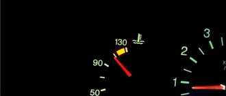
Operating temperature of Lada Granta 8 valve engine
Unstable engine operation when cold can create discomfort, which many people fix for money at a car service center. But, this malfunction can be fixed in your garage, with a minimum set of tools.
This engine trembles when starting
Of course, novice motorists first need.
Main reasons
So, first we need to consider what could be the reasons why the engine started to misfire when cold:
- Problems with spark plugs.
- Malfunction of high-voltage wires.
- Mass sensor malfunction (see " ").
- Fuel system malfunction.
- Valve clearances.
Elimination methods
Now that the main causes have been identified, you can proceed directly to identifying the specific cause and the elimination method that will lead to normalization of the operation of the main power unit. So, let's consider the sequence of actions aimed at eliminating the causes of the effect.
Spark plug
Dirty spark plugs
Accumulated carbon deposits or breakdown
elements may cause the fuel mixture to stop igniting in one of the cylinders. To fix the problem, you need to carry out a number of operations:
- Remove the terminal from the battery.
- We remove the high-voltage wires from the spark plugs.
- Using a spark plug wrench, we remove the spark plug sequentially from each cylinder.
- We carry out diagnostics, namely inspecting the element, as well as measuring gaps and resistance.
When a non-working spark plug is found, it must be replaced with a new one, having previously adjusted the gaps, and also checked for resistance. This is due to the fact that even from the manufacturer’s factory you can receive a defective part.
. Now, we install a new element and put everything back to its original form. Next, you need to check whether the negative effect has disappeared.
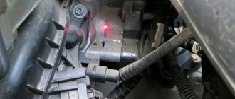
High voltage wires
High voltage wires are marked with arrows
High-voltage wires are another common cause of unstable engine operation.
Moreover, this effect will be visible not only when cold, but also at speed. Diagnostic operations are carried out quite easily:
- We remove the wires from the spark plugs and.
- We take measurements using a tester or an oscilloscope (if available).
Air filter
Part of the air filter replacement process
If the problem is not in the ignition, then you need to pay attention, first of all, to the air filter. Clogging of this element can lead to the engine stopping “breathing”, namely, the supply of the necessary air mixture to the main power unit is limited
This malfunction may affect operation when the engine is cold. To troubleshoot the problem, you must
Clogging of this element can lead to the engine stopping “breathing”, namely, the supply of the necessary air mixture to the main power unit is limited. This malfunction may affect operation when the engine is cold. To troubleshoot the problem it is necessary.
Valve clearances
Valve clearance adjustment process
So, it is worth checking the clearances on the valve mechanism and adjusting if necessary.
It is recommended not only to set the required clearance on each valve, but also to dismantle the cylinder head, and also check the condition of the valves, camshaft and combustion chamber cylinders. It is in these places that the problem may lie.
DMVR
A malfunction of the mass air flow sensor can cause unstable engine operation when cold.
Another common malfunction that directly affects the stable operation of a cold engine is the mass air flow sensor. Checking this electrical element is quite simple, as is replacing it. Therefore, every motorist will be able to do this without much effort and problems.
Fuel system
Fuel system diagram
The fuel system directly affects the stable operation of the engine in any mode. So, all this may be due to the fact that an unbalanced air-fuel mixture can not only disrupt the performance of the main power unit, but also lead to other consequences
Let's look at what elements of the fuel system you should pay attention to when looking for the cause:
ECU
Now, let's look at the last reason why the effect of three cylinders working may occur. Errors in the electronic engine control unit can also cause the “brains” to issue incorrect commands or not completely.
This malfunction can be cured quite simply; you need to connect to the control unit and read the necessary data. Next, you should reset all accumulated errors. If these operations do not help, then you should flash the control unit.
What does the price depend on?
Motorists who need engine overhaul of a VAZ-2114 are faced with different prices for such a service. The cost depends on the influence of factors:
- Engine capacity.
- The prestige of the service company, its pricing policy.
- Urgency.
- Scope of work.
- Difficulty of repair.
- The need for a specialist to visit.
- Cost of spare parts.
- Equipment used.
- Automotive technician qualification level.
The more work is required to restore the engine of a VAZ-2114 car, the more expensive the service of a specialist will cost. You will have to pay extra for urgency and a specialist visit.
Approximate price
On average, a major overhaul of a VAZ-2114 engine costs from 22,000 rubles. Engine repair cost broken down:
- Dismantling – 500 rubles .
- Installation – 600 rubles .
- Replacing oil scraper caps - 2000-4000 rubles .
- Pulling the engine sump - about 490 rubles .
- Crankshaft grinding - from 900 rubles .
- Replacing the crankshaft bearing - about 330 rubles .
- Honing and boring on a standard block - from 1000 rubles .
- Replacing the valve cover - 420-620 rubles .
- Replacement of the engine mount - from 540 rubles .
Replacing the engine on a VAZ-2114 will cost approximately 5,500 rubles . This does not include the price of a new unit.
Where and from whom can I order the service?
If an engine overhaul of a VAZ-2114 is required, then there are several options:
- Take the car to a car service center.
- Contact a private master.
- Repair the unit yourself.
A major type of repair requires extensive knowledge, skills, experience, certain equipment and tools. Therefore, only a master of a service center can carry out a high-quality engine restoration. Car service centers issue a warranty certificate. You should contact private traders only on the advice of good friends. Among such workers there are often low-skilled people. In addition, they do not provide a warranty card.
On cars of the Samara 2 series, the Volzhsky Automobile Plant installed injection engines with electronic, distributed fuel injection. And for the VAZ 2114, which appeared in 2001, and was launched into series in 2003, such a power plant was developed - model 2111. In subsequent years, various modifications of this car were produced and some of them were equipped with other engine models, such as - 21114, 11183, 21124 and 21126. But the most popular production cars were the VAZ 2114 with engines of models 2111 and 11183.
Operating principle and design of the VAZ-2115 heating system
If the heater in the car does not work, especially in the cold season, there is a possibility of being left without a means of transportation, since in the cold you can simply freeze inside the car.
In severe frosts, it is very difficult to clear the windshield of ice to ensure visibility, and with a non-working stove this becomes doubly problematic. You may not even be able to get to a service station.
But most often, if you know the operating principle, circuit and design of the VAZ-2115 stove, you can solve the problem on the spot yourself.
Construction of the VAZ-2115 heating system
The electrical diagram of the VAZ heater operation is represented by the following elements:
- Electric motor with fan. The fan drives hot air into the car interior and onto the windshield.
- Buttons and levers for switching heat level and air flow speed. The VAZ-2115 has 3 options for heat flow rates that can be adjusted.
- Additional resistances that provide the required rotation speed of the stove fan (step-down tungsten turn coils).
- Fuses and connection wires.
The diagram of the VAZ-2115 stove presented below clearly shows its operating structure and components.
Connection diagram for the VAZ heating system
- Mounting block.
- Ignition.
- Unloading ignition relay.
- Heater motor switch.
- Additional resistor.
- Stove motor.
- Stove control button.
- Heated rear window.
K7 is a relay that turns on the heated rear window.
Heater operation diagram
- Fan.
- Windshield defroster.
- Damper that distributes air flow to the central and side deflectors; zones that warm the feet of the driver and passenger.
- Damper that controls the stove.
- Radiator.
- Airflow to the driver's feet.
- Internal air duct.
The operation of the stove is based on the following principle
The cooling and heating system works the same on almost all VAZ car models. The heater is turned on using a regulator located in the car itself; antifreeze is supplied to the radiator. Its temperature after warming up reaches more than 80 degrees. After which the fan starts working, operating at one of 3 speed modes.
The fan begins to create a directed air flow. It moves from the outside of the heating system into the interior of the car. Using control flaps, the driver selects heating zones, there are three in total: on the feet, on the windshield and in the car interior.
The key element of a car's heating system is the fan, and if it fails, the heating will be lost. Without it, hot air will not enter the cabin, and to heat the interior of the VAZ-2115, it will take not a couple of minutes, but a couple of hours.
Major electrical failures of the heating system of the VAZ-2115
If no changes occur in the heating system at any position of the switch knob, then most likely the system motor is faulty (the brushes are worn out) or there is no voltage at the terminals. But also in this case there may be problems with the ignition switch or mounting block (fuse F4 has blown).
It is important for the proper operation of the car's heating system that there is no more than 3 ohms at the engine ground (installed under the hood). If the heater works normally at maximum engine speeds, and problems arise only at low speeds, then the cause of the malfunction most likely lies in the speed switch button or additional resistors
If you turn on the interior heating system and hear a noise and the heater is not blowing properly, this also indicates an engine problem.
Malfunctions may include jamming of the impeller or armature bearings. Malfunctions can be eliminated by replacing components or, if necessary, lubricating them.
But, as a rule, these actions have a short-term effect and the problem returns.
Over time, any equipment breaks down and requires repair.
Don’t forget that over time the system ages and wears out, so the older the car, the more it needs to be prepared for the heating season.
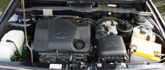
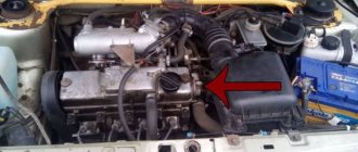
Design features of the VAZ 2114 engine
The main distinguishing feature of all engine models on the VAZ 2114 is that they have an injector installed. Electronic control of fuel injection, depending on the readings of a large number of different sensors that monitor a variety of parameters, including the composition of the exhaust gases, of course contributes to balanced and economical operation of the engine.
The engine itself on the VAZ 2114 is an in-line, four-stroke, eight-valve unit with a camshaft located on top. It has four cylinders, runs on gasoline and is cooled with a special liquid. In the engine compartment of a car, the engine is located transverse to the direction of travel. The photo of the VAZ 2114 engine shows its actual location relative to other units.
The cylinder block of this power unit is made of cast iron. All holes for antifreeze are formed in the casting mold, the oil passages are machined mechanically. The working cylinders are also machined. At the bottom of the block there are main bearing supports; covers for them are made during the manufacture of the block; they have an individual fit, so they cannot be replaced. When disassembling, you need to pay attention to the markings of these covers so as not to confuse them. Inserts made of an alloy of steel and aluminum are inserted into the covers and supports. Thrust half-rings are inserted into the third support, which prevent axial movement of the crankshaft.
The pistons are made of aluminum with steel rings cast into them. The pins are floating and the connecting rods are forged from steel. The bottom of the cylinder block covers the pan; there must be a gasket between them. Its integrity must be monitored, because the pan is a container for engine oil, which lubricates all rubbing parts during operation of the internal combustion engine. The lubrication oil system operates under pressure and spray. The pressure is created by an oil pump, which, taking lubricant from the sump, drives it through a direct-flow oil filter. It has a check valve that prevents oil from flowing back into the pan.
The crankshaft, located at the bottom of the cylinder block, has a flange. The flywheel is attached to this flange. A special installation mark is made on the flywheel by drilling for its correct location on the crankshaft flange. This mark should be located opposite the connecting rod journal of the fourth cylinder.
A pump, also called a coolant pump, is installed on the left side of the internal combustion engine cylinder block.
The cylinder head, or cylinder head, is made of aluminum. The cylinder head contains valves with bushings and seats and pushers with adjusting washers. The camshaft is located in the cylinder head from above and is clamped by supports to which the bearings are pressed. The cylinder head is closed with a cap with a neck for filling oil.
The camshaft and pump are driven by a belt from the crankshaft toothed pulley. Nearby there is another belt that spins the generator.
Interior tuning
For model 2115, car tuning with interior modernization involves many different modifications.
Installation of air conditioning is especially popular. You can install this device in your car yourself. To do this, you will need funds to purchase equipment, tools and the desire to improve the interior of your VAZ. You will have to pay for the opportunity to have a car with air conditioning, and not in the literal sense of the word. After all, after installing a new device, the car will begin to consume more current from the generator, and the fuel consumption rate will increase. In some cases, a special place will need to be equipped for the air conditioner, so adjusting the size will also require certain costs.
To avoid misunderstandings, you should immediately select an air conditioner model that is suitable for a given car brand. All parts of the device are connected to air ducts through which air will flow. Using fuses will help protect equipment from damage. In general, you can find a detailed connection diagram in the device instructions. This will help you complete all the work without problems.
The general connection diagram is as follows:
- compressor installation;
- installation of freon;
- connecting the electric fan.
The most popular tuning of a VAZ 2115 car is the installation of electric windows. Despite the fact that many models are already equipped with them at the factory, there are still many cars with manually lifting door windows. To install such a kit on a VAZ 2115, you will need to select elements according to the make of the car. Please note that some kits are only suitable for front doors.
When deciding to tune the VAZ 2115 panel, it is better to start with the backlight. Diode light bulbs are perfect for these purposes. The steps to connect them are simple and require a little attention and perseverance. An interesting styling option is also replacing the front and rear speakers and radio. After all the transformations, the VAZ 2115 tuning in the photo will be distinguished by its extraordinary solidity and modernity.
Block head and timing device
All front-wheel drive cars of the VAZ family, be it 2109, 2110 or 2114, have one cylinder head, common to all cylinders. They are mounted to the block using ten screws. During installation, a metal gasket is placed under it. This gasket is for single use and cannot be reused. There are five camshaft bearings at the top of the cylinder head.
The camshaft of the engine of the VAZ-2109 car has the index 21083. Some engines are equipped with 2110 or 2111 shafts; their design is slightly different from 21083, which allows for an increase in engine power. The shaft is cast from cast iron, there are five supports and eight cams on it that open the valves.
Seats are pressed into the cylinder head, as well as valve guides. On the inside of the bushings there are grooves for supplying lubricant; the bushings are closed on top with oil deflector caps.
The valves are made of steel, and the intake head is made of heat-resistant steel. They are mounted obliquely in one row. The inlet valve has a larger diameter than the outlet valve. The gaps between the valves and camshaft cams are adjusted using shims that have increased wear resistance.
Pushers are metal cups moving in the cylinder head holes. To improve wear resistance, the surface in contact with the ends of the valve stems is cemented.
Technical characteristics of the VAZ 2114 engine model 2111
- ICE type - in-line;
- four cylinders, two valves per cylinder;
- cylinder diameter - 82 mm;
- compression ratio - 9.8;
- ICE volume - 1.5 liters;
- engine power - 78 hp. With.;
- maximum torque - 116 Nm at 3000 rpm;
- average fuel consumption in mixed mode is 7.3 liters per 100 km;
- ICE weight - 127 kg;
- the service life of the power propulsion system is 150 thousand kilometers, during practical operation the service life reaches 250 thousand kilometers;
- real engine tuning is possible in various ways and without loss of service life the power can be increased to 120 hp. s., there is the potential to increase the power of the internal combustion engine to 180 hp. pp., but with a significant loss of power plant life.
Camshafts with modified cams
What is considered normal engine operating temperature?
Another popular method of changing the engine is installing a new camshaft with a modified cam profile. You can find it on sale quite often. The features of this method of increasing engine power include:
1. A change in the cam profile causes a shift in valve timing. This moment allows you to significantly increase power and torque, which will affect the acceleration dynamics of the vehicle.
2. In some cases, a composite shaft drive pulley is installed along with the camshaft. It also allows you to significantly increase the power of the vehicle engine.
Sidebar: Important: When installing a new camshaft, you should take into account the fact that mixing the valve timing leads to a significant increase in fuel consumption and a decrease in engine life. Therefore, the selection of the camshaft version should be carefully selected.
VAZ 2114 engine repair
During the operation of the internal combustion engine on a car, various failures and malfunctions may occur, which can be eliminated by self-repair or with the involvement of specialists. The need for a major overhaul of the power propulsion system, with its proper operation, arises when the mileage reaches 150,000 km. In this case, a VAZ 2114 engine overhaul is needed.
- Before you begin disassembling the engine, you need to drain the oil and coolant, and then wash the entire unit. Be sure to remove all attachments so as not to damage them during reassembly.
- Disconnect all pipes through which gasoline is supplied.
- Remove all systems and components related to the air supply, remove the air supply and exhaust hoses and pipes.
- Remove the cooling system pipes and crankcase breather. Don't forget to disconnect the throttle pipe.
- Remove the receiver, as well as the pipeline mounting bracket and the fuel rail, remove the injectors with regulators.
- Remove the wires with the ignition module and knock sensor. Unscrew the spark plugs. After this, unscrew all sensors.
- Remove the generator by first removing the tension belt. With the generator, remove all brackets and strips necessary for its installation and adjustment.
- Block the flywheel and remove the generator pulley.
- Remove the camshaft drive with the cover, tension mechanism and pulley.
- Unscrew the pump, remove the exhaust manifold and thermostat.
- Disconnect the oil filter and oil sump, then remove the oil pump.
- In order to remove the piston group, you need to unscrew the nuts from the connecting rod bolts and remove the cover.
- Since the flywheel is blocked, you need to unscrew its fastenings with the flange and remove the flywheel disk.
- Remove the caps from the main bearings along with the lower bearings.
- Carefully pull out the crankshaft. It must be handled very carefully to prevent damage and scratches.
- Remove the upper liners and thrust half-rings.
When overhauling an internal combustion engine, it is necessary to carefully inspect each unit, component or part. If mechanical damage is detected, the spare part must be replaced. All gaskets, washers and non-metallic parts also need to be replaced.
The VAZ 2114 injector engine is a series of engines that were installed on the Lada 2114 vehicle. Like many Lada models, the 2114 model received several power unit options over all years of production. So, the technical characteristics of each of them were different. Let's consider the design of the 2114 engine, as well as issues of maintenance, tuning and repair.
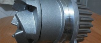
What does the lightweight flywheel of the VAZ 2114 give?
As the name suggests, a lightweight flywheel differs from a standard flywheel in being lighter in weight. The difference is about one and a half kilograms. This is achieved by removing excess metal at large radii, which does not lead to a decrease in the strength of the part. There are ready-made lightweight versions of flywheels on sale, but some craftsmen, if they have the appropriate equipment and skills, modify the standard flywheel themselves. This is a rather labor-intensive and very responsible operation, so it is easier and cheaper to purchase a finished product. What does a lightweight flywheel give? Due to its smaller mass, it has less inertia, so the engine needs to spend less energy accelerating to maximum speed. As a result, the dynamics increase by approximately 3-4%. For everyday use, this indicator may not matter. But in sports competitions, for example, in rallies and, especially, in drag racing, the lightweight flywheel of the VAZ 2114 can play an important role. It should be remembered that tuning the flywheel must be supplemented with modifications to the crankshaft and transmission. Only in this case can a noticeable increase in vehicle dynamics be achieved.
Lubricating parts
Combined engine lubrication device for the VAZ-2109 (2110). Oil is supplied to the main and connecting rod bearings, as well as to the camshaft supports under pressure; the cylinders, pistons, pins and rings, camshaft cams and pushers are lubricated by splashing; all other associated parts are lubricated by gravity.
A gear-type oil pump with a bypass valve is installed at the front of the block. The oil receiver is mounted using bolts on the cover of the second main bearing and the pump housing. The oil filter is non-separable and has bypass and anti-drainage valves. The design of the lubrication system and other engine systems is discussed in detail in separate articles.
Crankcase ventilation is forced, gases are removed through the oil separator.
Specifications
VAZ 2114 car
The technical characteristics of the VAZ 2114 engine are quite typical for the 2113-2115 series of cars. In addition, this power unit is developed on the basis of the “eight” engine, which has declared itself to be reliable and easy to repair. The car was produced from 2001 to 2013. During this period, the vehicle received five valuable power units.
VAZ 2114 engine structure
As was said earlier, the 2114 was equipped with five different power units, which differed in power and valve mechanism. Three of them had 8 valves, and the other two had 16. The gas distribution mechanism had a belt drive. Until 2007, the engine was equipped with a simple on-board computer, which did not regulate the operation of the engine based on sensor readings. Therefore, the motorist had to regulate the processes the old fashioned way, manually. Since 2007, an ECU was installed, which, receiving data from sensors, independently adjusted many processes.
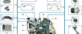
Design features of the engine.
Since the second generation had a so-called two-way electronic engine control unit, it is worth considering what electrical circuit was installed.
Electrical diagram of a VAZ 2114 car.
Main characteristics of the motor
All engines that were installed on the vehicle had approximately the same characteristics and design features. So, the motor is easy to service and repair with your own hands. Let's look at the main technical characteristics of the VAZ 2114 engine:
VAZ 2111
| Name | Index |
| Volume | 1.5 liter (1499 cm3) |
| Number of cylinders | 4 |
| Number of valves | 8 |
| Fuel | Petrol |
| Injection system | Injector |
| Power | 77 hp |
| Fuel consumption | 8.2 l/100 km |
| Cylinder diameter | 82 mm |
VAZ 21114
| Name | Index |
| Volume | 1.6 liter (1596 cc) |
| Number of cylinders | 4 |
| Number of valves | 8 |
| Fuel | Petrol |
| Injection system | Injector |
| Power | 81.6 hp |
| Fuel consumption | 7.6 l/100 km |
| Cylinder diameter | 82 mm |
VAZ 11183
| Name | Index |
| Brand | 11183 |
| Marking | 1.6 8V |
| Type | Injector |
| Fuel | Petrol |
| Valve mechanism | 8 valve |
| Number of cylinders | 4 |
| Fuel consumption | 9.6 liters |
| Piston diameter | 82 mm |
| Resource | 200 – 250 thousand km |
VAZ 21124
| Name | Index |
| Volume | 1.6 liter (1599 cc) |
| Number of cylinders | 4 |
| Number of valves | 16 |
| Fuel | Petrol |
| Injection system | Injector |
| Power | 89.1 hp |
| Fuel consumption | 7.0 l/100 km |
| Cylinder diameter | 82 mm |
VAZ 21126
| Name | Index |
| Volume | 1.6 liter (1597 cc) |
| Number of cylinders | 4 |
| Number of valves | 16 |
| Fuel | Petrol |
| Injection system | Injector |
| Power | 97.9 hp |
| Fuel consumption | 7.2 l/100 km |
| Cylinder diameter | 82 mm |
Engine VAZ 2114.
All engines were equipped with 5-speed manual transmissions. Engine volume ranges from 1.5 to 1.6 liters. This car was not equipped with a large power unit. The average engine power of the VAZ 2114 is 85 horsepower.
Replacing the Lada 2115i engine (VAZ 2115i)
Newer VAZs, despite criticism, are still evolving compared to their predecessors. Thus, in newer models, instead of a standard engine mount, the manufacturer used a so-called engine mount, the appearance of which made it possible to significantly increase the level of comfort in domestically produced cars.
There are three pillows on the “fourteenths”:
Engine mounts are constantly under heavy load, even when the car is just standing still, which cannot but affect their condition. Over time, engine mounts, made of durable rubber, become unusable and require replacement, which is indicated to the car owner by characteristic signs.
- The appearance of strong vibration, especially at low speeds;
- Metallic knocking coming from under the hood;
- From time to time there is a sound similar to the ticking of a clock;
- Visual damage (cracks on the surface of the cushions, large play in the joints).
To replace the engine mount you will need:
1. Jack up the front part of the car, and then install safety supports under the body.
3. Next, unscrew the nut completely and try to pull out the fastening bolt. If the bolt does not fit, try raising the engine a little more.
5. Replacement of the remaining engine mounts is carried out according to the same principle; differences can only be in the location. For example, changing the front engine mount is relatively simple, the side one is more difficult, but the rear engine mount (box mount) causes a lot of trouble and requires a lift and some skill.
Relevant: WHAT ARE ENGINE MOUNTS? SIGNS OF MALFUNCTION AND REPLACEMENT OF ENGINE MOUNTS FOR VAZ 2110
In this article we will talk about the engines that are installed on the entire Samar family.
VAZ 2114 2115 2116 are equipped with 1.5 and 1.6 liter injection engines.
- The 1.5 liter engine was installed on VAZ 2114 2113 2115 up to and including 2007.
- The engine index according to the passport is 2111.
- Characteristics of the 1.5L Engine.
- Volume - 1500 cm³ (58 kW).
- Torque - 116 Nm (at 3000 rpm).
- Power - 77 hp
- Acceleration to 100 km/h - 13.2 seconds.
- The 1.6 liter engine was installed on VAZ 2114 2113 2115 up to and including 2007.
- The engine index according to the passport is 21114/1116.
- Engine capacity - 1600 cm³.
- Power - 81 hp
- Torque - 132 Nm (at 3800 rpm).
- Acceleration to 100 km/h - 13.2 seconds.
Engine 1.6l 16kl
Engine 21124 1.6l 16kl:
Engine 21126 1.6l 16kl:
Which engine is better: 1.5 8kl or 1.6 8kl?
In essence, the 1.5 and 1.6L 8cl engines are no different, except for volume, exhaust standards, fuel supply systems and a couple of sensors. Therefore, the main distinguishing point is the engine size. A difference of 0.1 liters gives much more torque from the bottom, a little more maximum power and, perhaps, even the same or even lower engine consumption than a 1.5 liter. The only negative is that it is noisier at idle.
Which engine is better, 1.6 16kl or 8kl?
In terms of manufacturability, 16kL engines are superior to 8kl engines, so if there is an option to take a 16kl motor, then it would be nice to go with this option, but everything has its own nuances.
- The best cylinder blowing is more power.
- More stable engine operation - less noise.
- Greater engine efficiency means lower fuel consumption.
Features of the 2111 (1.5i) engine power system
Location of elements of the 2111 (1.5i) engine power supply system in the engine compartment:
1 - receiver; 2 — vacuum supply hose to the fuel pressure regulator; 3 — throttle assembly; 4 - fuel rail; 5 — fuel pressure regulator; 6 — air supply hose to the throttle valve; 7 - adsorber; 8 — air filter; 9, 10 and 11 — hoses of the crankcase ventilation system; 12 — throttle valve drive cable; 13 — diagnostic fitting
Read more: Resistances for 12V LED
combined with the fuel level indicator sensor into a single unit - fuel module
(often called an electric fuel pump). The pressure pump delivers fuel from the tank through the fuel filter to the fuel rail.
Engine Fuel Module 2111 (1.5i):
1 — fuel level indicator sensor; 2 — connecting block; 3 — inlet pipe; 4 - outlet (discharge) pipe; 5 — module cover; 6 — module cover guide; 7 - electric fuel pump in a plastic casing; 8 - intake chamber
Fuel rail for engine 2111 (1.5i) complete with injectors:
1 — diagnostic fitting; 2 - fuel rail; 3 — fuel supply tube to the fuel rail; 4 — fuel pressure regulator; 5 — tube for draining (draining) fuel into the tank; 6, 7, 8 and 9 - injectors
Fuel pressure control
installed on the fuel rail. Excess fuel is returned to the tank through the fuel return line.
Engine power supply system diagram 2111 (1.5i):
1 - nozzle; 2 - fuel rail; 3 — diagnostic fitting; 4 - adsorber; 5 - check valve; 6 — throttle assembly; 7 - gravity valve; 8 — safety (two-way) valve; 9 - separator; 10 - filler pipe; 11 — fuel filter; 12 — fuel drain line; 13 — fuel line hose connecting the outlet pipe of the fuel module to the fuel filter; 14 — fuel module; 15 — fuel tank; 16 — fuel line connecting the fuel filter to the fuel rail; 17 - fuel pressure regulator
Replacing injectors
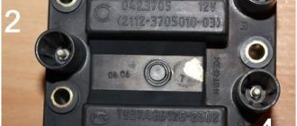
Ignition module VAZ 2115 injector 8 valves how to check
The difficulty in identifying problems in the operation of injectors is that the fuel system is quite branched and it is necessary to diagnose the functionality of all its parts. For example, a malfunction such as a decrease in engine power can have two reasons - failure of the injectors or exhaustion of the pump's life.
Clogged injectors can result in sudden jerking of the engine while driving or unstable idle speed. In addition, an increase in fuel consumption can be considered a sign of injector failure.
You can check the functionality of each injector even without removing them. Simply start the engine and remove the wires from the connector of each injector one by one. If immediately after removal the engine starts to twitch or stalls, then the injector is fine. If the stability of the engine does not change with removal of the wire, then the injector needs to be thoroughly cleaned or even replaced.
Video: replacing injectors on VAZ 2108 - 2115 injectors
The procedure for dismantling and installing injectors is not particularly difficult, but it does take a lot of time. You need to prepare a set of tools in advance:
2 open-end wrenches for 17;
screwdriver with a flat thin blade;
hex key 5.
Before removing the injectors for replacement, it is necessary to relieve the pressure in the vehicle's fuel system. This is a necessary measure to ensure safe work and eliminate the possibility of injury.
To relieve fuel pressure, you must turn off the fuel pump. It is located in VAZ 2114/2115 cars in the fuel tank. The easiest way to get to the pump is through the hatch located under the rear seat cushion. For this:
The seat needs to be reclined.
Find a small hatch under the rug.
Unscrew the screws securing the hatch.
Remove the cover and remove the contact block from the fuel pump housing.
Then you need to start the engine. The engine will run on the amount of fuel that remains in the system, since the pump will not build up pressure after removing the block. You must wait until the engine has completely used up the remaining gasoline and stalls.
The procedure for removing injectors is as follows:
Open the hood of the car and remove the wire from the negative terminal on the battery.
For ease of dismantling, it is recommended to remove the air filter box. It will prevent free access to the engine.
After that, use your finger to snap off the plastic retainer on the engine and disconnect the connector from the throttle valve.
The connector from the idle air control regulator is removed in the same way.
Next, you need to disconnect the connector block from the wiring harness of the injectors themselves.
The injectors can only be removed together with the fuel rail. Therefore, you need to unscrew the bolts securing the ramp to the body.
After which it will be possible to move the ramp to the side so that each of the nozzles moves slightly out of the mounting socket. The wires are removed from the injectors, otherwise it will be impossible to pull out the ramp.
The ramp is pulled out and placed in a clean place. Now you can easily remove all the injectors - they are pressed out using a plastic clamp.
Disconnecting the injectors is only possible after dismantling the ramp itself
Accordingly, new products are inserted in place of the old ones. And then the installation work is carried out in the reverse order.
Motor maintenance
When the design and main technical characteristics inherent in the VAZ 2114 engine have been reviewed, it is necessary to consider maintenance and provide answers to questions that motorists are increasingly asking.
Maintenance
If you believe the plant, the manufacturer, the VAZ 2114 engine must be serviced every 12-15 thousand kilometers. It depends on what marking the motor is installed on the vehicle. Maintenance scheme for all engines installed on the “fourteenth” model:
- At the first maintenance, the oil, oil filter and air filter element are replaced, as well as the functionality of all systems is checked.
- The second maintenance is done after 12,000 km. In this case, it is necessary to change the oil and oil filter element.
- Third maintenance – 25,000 km, replacing not only the oil, but also the air filter, and ongoing repair of faults.
- After 45,000 km, it is necessary to replace the timing belt and roller so that the VAZ 2114 engine does not have to be overhauled.
Electronic control unit
This block monitors information coming from sensors and is responsible for controlling the fuel injection system. The control unit contains a diagnostic system, thanks to which a system failure is recognized. It signals all problems occurring in the system through a light located on the dashboard - Check Engine. It also stores all errors that have ever occurred. Subsequently, their codes help to understand when diagnosing problems.
Source