Currently, vehicles mainly use four-stroke piston internal combustion engines.
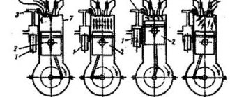
A single-cylinder engine (Fig. a) contains the following main parts: cylinder 4, crankcase 2, piston 6, connecting rod 3, crankshaft 1 and flywheel 14. One end of the connecting rod is pivotally connected to the piston using piston pin 5, and the other end is also connected articulated with the crankshaft crank.
When the crankshaft rotates, the piston moves back and forth in the cylinder. For one revolution of the crankshaft, the piston makes one stroke down and one up. A change in the direction of piston movement occurs at the dead points - top (TDC) and bottom (BDC).
The top dead center is the position of the piston farthest from the crankshaft (the uppermost position with a vertical engine), and the bottom dead center is the position of the piston closest to the crankshaft (the lowestmost position with a vertical engine).
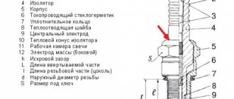
Rice. Schematic diagram (a) of a single-cylinder four-stroke piston internal combustion engine and its diagram (b) for determining the parameters: 1 - crankshaft; 2 - crankcase; 3 — connecting rod; 4 - cylinder; 5 — piston pin; 6 - piston; 7 — inlet valve; 8 — inlet pipeline; 9 - camshaft; 10 — spark plug (petrol and gas engines) or fuel injector (diesels); 11 — exhaust pipeline; 12 — exhaust valve; 13 — piston rings; 14 - flywheel; D—cylinder diameter; r is the radius of the crank; S - piston stroke
The distance S (Fig. b) between TDC and BDC is called the piston stroke. It is calculated using the formula:
S = 2r, where r is the radius of the crankshaft crank.
The piston stroke and cylinder diameter D determine the main dimensions of the engine. In transport engines the S/D ratio is 0.7 -1.5. When S/D < 1 the engine is called short-stroke, and when S/D > 1 it is called long-stroke.
As the piston moves down from TDC to BDC, the volume above it changes from minimum to maximum. The minimum volume of the cylinder above the piston when it is at TDC is called the combustion chamber. The volume of the cylinder released by the piston when it moves from TDC to BDC is called working volume. The sum of the displacements of all cylinders represents the displacement of the engine. Expressed in liters, it is called engine displacement. The total volume of a cylinder is determined by the sum of its working volume and the volume of the combustion chamber. This volume is enclosed above the piston when it is at BDC.
An important characteristic of the engine is the compression ratio, determined by the ratio of the total volume of the cylinder to the volume of the combustion chamber. The compression ratio shows how many times the charge entering the cylinder (air or fuel-air mixture) is compressed when the piston moves from BDC to TDC. For gasoline engines, the compression ratio is 6 - 14, and for diesel engines - 14 - 24. The adopted compression ratio largely determines the engine power and its efficiency, and also significantly affects the toxicity of exhaust gases.
The operation of a piston internal combustion engine is based on the use of pressure on the piston of gases formed during the combustion of fuel and air mixtures in the cylinder. In gasoline and gas engines, the mixture is ignited by the spark plug 10, and in diesel engines - due to compression. There are concepts of combustible and working mixtures. The combustible mixture consists of fuel and clean air, and the working mixture also includes the exhaust gases remaining in the cylinder.
A set of sequential processes that are periodically repeated in each cylinder of an engine and ensure its continuous operation is called the work cycle. The working cycle of a four-stroke engine consists of four processes, each of which occurs in one piston stroke (stroke), or half a revolution of the crankshaft. A full working cycle is carried out in two revolutions of the crankshaft. It should be noted that in the general case, the concepts of “work process” and “stroke” are not synonymous, although for a four-stroke piston engine they are almost the same.
The piston performs a number of important functions:
- ensures the transmission of mechanical forces to the connecting rod;
- is responsible for sealing the fuel combustion chamber;
- ensures timely removal of excess heat from the combustion chamber
Piston operation takes place in difficult and in many ways dangerous conditions - at elevated temperatures and increased loads, therefore it is especially important that pistons for engines are efficient, reliable and wear-resistant. That is why light but ultra-strong materials are used for their production - heat-resistant aluminum or steel alloys. Pistons are made by two methods - casting or stamping.
How does it function and what does it consist of?
The piston internal combustion engine has a complex structure and consists of:
- A housing, including a cylinder block, a cylinder head;
- Gas distribution mechanism;
- Crank mechanism (hereinafter referred to as crank mechanism);
- A number of auxiliary systems.
The crankshaft is the link between the energy released during combustion of the fuel-air mixture (hereinafter referred to as FA) in the cylinder and the crankshaft, which ensures the movement of the vehicle. The gas distribution system is responsible for gas exchange during the operation of the unit: access of atmospheric oxygen and fuel assemblies to the engine, and timely removal of gases formed during combustion.
The design of a simple piston engine
Auxiliary systems are presented:
- Intake, ensuring the supply of oxygen to the engine;
- Fuel, represented by a fuel injection system;
- Ignition, which provides a spark and ignition of fuel assemblies for engines running on gasoline (diesel engines are characterized by self-ignition of the mixture due to high temperature);
- A lubrication system that reduces friction and wear of contacting metal parts using machine oil;
- A cooling system that prevents overheating of the working parts of the engine, ensuring the circulation of special liquids such as antifreeze;
- An exhaust system that ensures the removal of gases into the corresponding mechanism, consisting of exhaust valves;
- A control system that provides monitoring of the functioning of the internal combustion engine at the electronics level.
The main working element in the described unit is considered to be the internal combustion engine piston , which itself is a prefabricated part.
Engine piston requirements
- The piston, moving in the cylinder, allows compressed gases, the product of fuel combustion, to expand and perform mechanical work. It must be resistant to high temperature, gas pressure and reliably seal the cylinder bore.
- Meet the requirements of the friction pair in order to minimize mechanical losses and wear.
- Experiencing loads from the combustion chamber and reaction from the connecting rod, it must withstand mechanical stress.
- When performing reciprocating motion at high speed, it must load the crank mechanism with inertial forces as little as possible.
Extreme conditions determine the material used to make the pistons
The piston is operated under extreme conditions, characterized by high pressure, inertial loads and temperatures. That is why the main requirements for materials for its manufacture include:
- high mechanical strength;
- good thermal conductivity;
- low density;
- low coefficient of linear expansion, antifriction properties;
- good corrosion resistance.
The required parameters are met by special aluminum alloys, which are characterized by strength, heat resistance and lightness. Less commonly, gray cast iron and steel alloys are used in the manufacture of pistons. Pistons can be:
- cast;
- forged.
In the first version, they are made by injection molding. Forged ones are made by stamping from an aluminum alloy with a small addition of silicon (on average, about 15%!), which significantly increases their strength and reduces the degree of piston expansion in the operating temperature range.
We recommend: How does an internal combustion engine work and how does it work?
Consider the duty cycle of a gasoline engine
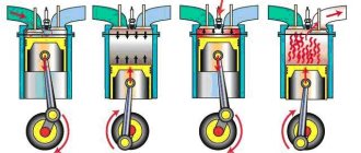
The first stroke of the operating cycle is intake. The piston moves from TDC to BDC, while the intake valve 7 is open and the exhaust valve 12 is closed, and the combustible mixture enters the cylinder under vacuum. When the piston reaches BDC, the intake valve closes and the cylinder is filled with the working mixture. For most gasoline engines, the combustible mixture is formed outside the cylinder (in the carburetor or intake manifold 8).
The next step is compression. The piston moves back from BDC to TDC, compressing the working mixture. This is necessary for its faster and more complete combustion. The inlet and outlet valves are closed. The degree of compression of the working mixture during the compression stroke depends on the properties of the gasoline used, and primarily on its anti-knock resistance, characterized by the octane number (for gasoline it is 76 - 98). The higher the octane number, the greater the anti-knock resistance of the fuel. If the compression ratio is excessively high or the anti-knock resistance of gasoline is low, detonation (as a result of compression) ignition of the mixture may occur and normal engine operation may be disrupted. By the end of the compression stroke, the pressure in the cylinder increases to 0.8...1.2 MPa, and the temperature reaches 450...500°C.
The compression stroke is followed by expansion (power stroke) as the piston moves back down from TDC. At the beginning of this stroke, even with some advance, the combustible mixture is ignited by spark plug 10. In this case, the intake and exhaust valves are closed. The mixture burns very quickly, releasing a large amount of heat. The pressure in the cylinder increases sharply, and the piston moves to the center of gravity, causing crankshaft 1 to rotate through connecting rod 3. At the moment of combustion of the mixture, the temperature in the cylinder rises to 1800 ... 2000 ° C, and the pressure - to 2.5 ... 3.0 MPa .
The last stroke of the working cycle is release. During this stroke, the intake valve is closed and the exhaust valve is open. The piston, moving upward from BDC to TDC, pushes out the exhaust gases remaining in the cylinder after combustion and expansion through the open exhaust valve into exhaust pipe 11. Then the working cycle is repeated.
The operating cycle of a diesel engine has some differences from the considered cycle of a gasoline engine. During the intake stroke, not a combustible mixture, but clean air enters the cylinder through pipeline 8, which is compressed during the next stroke. At the end of the compression stroke, when the piston approaches TDC, finely atomized diesel fuel is injected into the cylinder under high pressure through a special device - an injector screwed into the upper part of the cylinder head. In contact with air, which has a high temperature due to compression, fuel particles quickly burn. A large amount of heat is released, as a result of which the temperature in the cylinder rises to 1700...2000 °C, and the pressure - to 7...8 MPa. Under the influence of gas pressure, the piston moves downwards - a working stroke occurs. The exhaust strokes of diesel and gasoline engines are similar.
In order for the operating cycle in the engine to occur correctly, it is necessary to coordinate the opening and closing moments of its valves with the crankshaft speed. This is done as follows. The crankshaft, using a gear, chain or belt drive, rotates another engine shaft - the camshaft 9, which must rotate twice as slow as the crankshaft. The camshaft has profiled projections (cams) that directly or through intermediate parts (pushers, rods, rocker arms) move the intake and exhaust valves. During two revolutions of the crankshaft, each valve, intake and exhaust, opens and closes only once: during the intake and exhaust strokes, respectively.
The seal between the piston and the cylinder, as well as the removal of excess oil from the cylinder walls, is provided by special piston rings 13.
The crankshaft of a single-cylinder engine rotates unevenly: with acceleration during the power stroke and deceleration during the remaining auxiliary strokes (intake, compression and exhaust). To increase the uniformity of rotation of the crankshaft, a massive disk is installed at its end - a flywheel 14, which accumulates kinetic energy during the power stroke and releases it during the remaining strokes, continuing to rotate by inertia.
However, despite the presence of a flywheel, the crankshaft of a single-cylinder engine does not rotate evenly enough. When the working mixture ignites, significant shocks are transmitted to the engine crankcase, which quickly damages the engine itself and its mounting parts. Therefore, single-cylinder engines are rarely used, mainly on two-wheeled vehicles. On other machines, multi-cylinder engines are installed, which ensure more uniform rotation of the crankshaft due to the fact that the piston stroke in different cylinders does not occur simultaneously. The most widely used engines are four-, six-, eight- and twelve-cylinder engines, although some vehicles also use three- and five-cylinder engines.
Multi-cylinder engines usually have an in-line or V-shaped cylinder arrangement. In the first case, the cylinders are installed in one line, and in the second - in two rows at a certain angle to each other. This angle for various designs is 60... 120°; for four- and six-cylinder engines it is usually 90°. Compared to in-line V-twin engines of the same power, they are shorter in length, height and weight. The numbering of the cylinders is carried out sequentially: first, from the front part (toe), the cylinders of the right (in the direction of movement of the car) half of the engine are numbered, and then, also starting from the front part, the left half.
Uniform operation of a multi-cylinder engine is achieved if the alternation of the power stroke in its cylinders occurs through equal angles of rotation of the crankshaft. The angular interval through which identical strokes will be uniformly repeated in different cylinders can be determined by dividing 720° (the angle of rotation of the crankshaft at which a full working cycle is completed) by the number of engine cylinders. For example, an eight-cylinder engine has an angular interval of 90°.
The sequence of alternating strokes of the same name in different cylinders is called the engine operating order. The operating procedure must be such as to reduce to the greatest extent the negative impact on engine operation of inertial forces and moments arising due to the fact that the pistons move unevenly in the cylinders and their acceleration changes in magnitude and direction. For four-cylinder in-line and V-twin engines, the operating order can be as follows: 1 - 2 - 4 - 3 or 1 - 3 - 4-2, for six-cylinder in-line and V-twin engines - respectively 1 - 5-3 - 6 - 2- 4 and 1 - 4 - 2 - 5 - 3 - 6, and for eight-cylinder V-engines - 1 - 5 - 4 - 2 - 6 - 3 - 7 - 8.
We recommend: Briefly about car rental
In order to more efficiently use the working volume of the cylinders and increase their power, some designs of piston engines are pressurized with air with a corresponding increase in the amount of injected fuel. To provide boost, i.e. create excess pressure at the inlet of the cylinder, gas turbine compressors (turbocompressors) are most often used. In this case, the energy of exhaust gases is used to pump air, which, leaving the cylinders at high speed, rotates the turbine wheel of the turbocharger, mounted on the same shaft as the pump wheel. In addition to turbochargers, mechanical superchargers are also used, the working parts of which (pump wheels) are driven into rotation from the engine crankshaft using a mechanical transmission.
To better fill the cylinders with a combustible mixture (gasoline engines) or clean air (diesel engines), as well as to more completely clean them from exhaust gases, the valves should open and close not when the pistons are at TDC and BDC, but with some advance or delay. The opening and closing moments of the valves, expressed in degrees through the angles of rotation of the crankshaft relative to TDC and BDC, are called valve timing and can be represented in the form of a pie chart.
The intake valve begins to open during the exhaust stroke of the previous operating cycle, when the piston has not yet reached TDC. At this time, the exhaust gases exit through the exhaust pipe and, due to the inertia of the flow, carry with them fresh charge particles from the opened intake pipe, which begin to fill the cylinder even in the absence of vacuum in it. By the time the piston reaches TDC and begins its downward movement, the intake valve is already open by a significant amount, and the cylinder is quickly filled with fresh charge. The advance angle of the intake valve opening for different engines varies within 9...33°. The intake valve will close when the piston passes BDC and begins to move up on the compression stroke. Until this time, a fresh charge fills the cylinder by inertia. The retardation angle p of the intake valve closure depends on the engine model and is 40... 85°.
Rice. Circular diagram of the valve timing of a four-stroke engine: a - angle of advance of the intake valve opening; p is the delay angle of the intake valve closing; y is the advance angle of the exhaust valve opening; b - retardation angle of exhaust valve closing
The exhaust valve opens during the power stroke, when the piston has not yet reached BDC. In this case, the piston work required to displace the exhaust gases is reduced, compensating for some loss of gas work due to the early opening of the exhaust valve. The angle Y of the advance of the opening of the exhaust valve is 40...70°. The exhaust valve closes slightly later than the piston reaches TDC, i.e., during the intake stroke of the next operating cycle. When the piston begins to descend, the remaining gases will still leave the cylinder by inertia. Angle 5 of the delay in closing the exhaust valve is 9... 50°.
The angle a + 5, at which the intake and exhaust valves are simultaneously slightly open, is called the valve overlap angle. Due to the fact that this angle and the gaps between the valves and their seats are small in this case, there is practically no charge leakage from the cylinder. In addition, filling the cylinder with fresh charge is improved due to the high flow rate of exhaust gases through the exhaust valve.
The advance and retard angles, and therefore the duration of valve opening, should be greater, the higher the engine crankshaft speed. This is due to the fact that in high-speed engines all gas exchange processes occur faster, and the inertia of the charge and exhaust gases does not change.
Rice. Schematic diagram of a gas turbine engine: 1 - compressor; 2 - combustion chamber; 3 — compressor turbine; 4 - power turbine; M - torque transmitted to the machine transmission
The principle of operation of a gas turbine engine (GTE) is illustrated in the figure. Air from the atmosphere is sucked in by compressor 2, compressed in it and supplied to combustion chamber 2, where fuel is also supplied through the nozzle. In this chamber, the fuel combustion process occurs at constant pressure. Gaseous combustion products enter the turbine and compressor 3, where part of their energy is spent on driving the compressor that pumps air. The remaining part of the energy of the gases is converted into mechanical work of rotation of the free or power turbine 4, which is connected through a gearbox to the transmission of the machine. In this case, gas expansion occurs in the compressor turbine and free turbine with a decrease in pressure from the maximum value (in the combustion chamber) to atmospheric pressure.
The working parts of a gas turbine engine, unlike similar elements of a piston engine, are constantly exposed to high temperatures. Therefore, to reduce it, it is necessary to supply significantly more air into the combustion chamber of a gas turbine engine than is required for the combustion process.
Step-by-step operating diagram
The operation of an internal combustion engine is based on the energy of expanding gases. They are the result of combustion of fuel assemblies inside the mechanism. This physical process forces the piston to move in the cylinder. In this case, the fuel can be:
- Liquids (gasoline, diesel fuel);
- Gases;
- Carbon monoxide as a result of burning solid fuels.
Engine operation is a continuous closed cycle consisting of a certain number of cycles. The most common internal combustion engines are of two types, differing in the number of cycles:
- Two-stroke, producing compression and stroke;
- Four-stroke - characterized by four stages of equal duration: intake, compression, power stroke, and final - exhaust, this indicates a fourfold change in the position of the main working element.
The beginning of the stroke is determined by the location of the piston directly in the cylinder:
- Top dead center (hereinafter referred to as TDC);
- Bottom dead center (hereinafter referred to as BDC).
By studying the operating algorithm of a four-stroke model, you can thoroughly understand the principle of operation of a car engine .
Intake occurs by passing the working piston from top dead center through the entire cavity of the cylinder with simultaneous retraction of the fuel assembly. Based on design features, mixing of incoming gases can occur:
- In the intake manifold, this is relevant if the engine is gasoline with distributed or central injection;
- In the combustion chamber, if we are talking about a diesel engine, as well as an engine running on gasoline, but with direct injection.
The first stroke takes place with the intake valves of the gas distribution mechanism open. The number of intake and exhaust valves, how long they remain open, their size, and their state of wear are factors that affect engine power. The piston at the initial stage of compression is placed at BDC. Subsequently, it begins to move upward and compress the accumulated fuel assembly to the dimensions determined by the combustion chamber. The combustion chamber is the free space in the cylinder that remains between the top of the cylinder and the piston at top dead center.
The second stroke involves closing all engine valves. The tightness of their fit directly affects the quality of compression of the fuel assembly and its subsequent ignition. Also, the level of wear of engine components has a great influence on the quality of fuel assembly compression. It is expressed in the size of the space between the piston and the cylinder, in the tightness of the valves. The engine compression level is the main factor influencing its power. It is measured by a special device called a compression meter.
We recommend: Thermostat: principle of operation, types, design, photo, video.
The working stroke begins when the ignition system , generating a spark. The piston is in the maximum upper position. The mixture explodes, gases are released, creating increased pressure, and the piston is set in motion. The crank mechanism, in turn, activates the rotation of the crankshaft, which ensures the movement of the car. All system valves are in the closed position at this time.
The exhaust stroke is the final stroke in the cycle under consideration. All exhaust valves are in the open position, allowing the engine to “exhale” combustion products. The piston returns to its starting point and is ready to begin a new cycle. This movement contributes to the release of exhaust gases into the exhaust system, and then into the environment.
The operating diagram of an internal combustion engine , as mentioned above, is based on cyclicity. Having examined in detail how a piston engine works , we can summarize that the efficiency of such a mechanism is no more than 60%! This percentage is due to the fact that at a given moment the power stroke is performed in only one cylinder.
Not all the energy received at this time is directed towards moving the car. Part of it is spent on maintaining the flywheel in motion, which, by inertia, ensures the operation of the car during the other three strokes.
A certain amount of thermal energy is involuntarily wasted on heating the housing and exhaust gases. That is why the power of a car engine is determined by the number of cylinders, and as a result, the so-called engine volume, calculated using a certain formula as the total volume of all working cylinders.
How does it work
Fuel, burning in the space above the piston, releases a huge amount of heat in each engine operating cycle.
The temperature of the burnt gases reaches 2000 degrees. They will transfer only part of the energy to the moving parts of the engine; the rest will heat the engine in the form of heat. What remains will fly away into the chimney along with the exhaust gases. Therefore, if we do not cool the piston, it will melt after some time. This is an important point for understanding the operating conditions of the piston group. Let us repeat the well-known fact - the heat flow is directed from more heated bodies to less heated ones.
The hottest is the working fluid, or, in other words, the gases in the combustion chamber. The heat will be transferred to the surrounding air - the coldest. The air, washing the radiator and engine housing, cools the coolant, cylinder block and head housing. All that remains is to find the bridge through which the piston transfers its heat to the block and antifreeze. There are four ways.
The first path that provides the most flow is through the piston rings. Moreover, the first ring plays the main role, as it is located closer to the bottom. This is the shortest path to coolant through the cylinder wall. The rings are simultaneously pressed against the piston grooves and the cylinder wall. They provide more than 50% of the heat flow.
The second coolant in the engine is oil. Having access to the hottest parts of the engine, oil mist carries away and transfers a significant part of the heat from the hottest spots to the oil pan. In the case of using oil nozzles that direct the jet to the inner surface of the piston bottom, the share of oil in heat transfer can reach 30 - 40%.
But when loading the oil with the function of a coolant, care must be taken to cool it. Otherwise, overheated oil may lose its properties. Also, the higher the oil temperature, the less heat it can tolerate.
Third way. Part of the heat is taken away for heating by the fresh air-fuel mixture entering the cylinder. The amount of fresh mixture and the amount of heat that will be removed depends on the operating mode and the degree of throttle opening. But the heat produced by combustion is also proportional to the charge. This cooling path is pulsed in nature. It is fast-paced and highly effective, because... heat is taken from the side from which the piston heats up.
Care must be taken to transfer heat through the piston rings. If we block this path, then it is unlikely that the engine will withstand long-term forced conditions. The temperature will rise, the piston material will “float”, and the engine will collapse.
Let's remember about compression. Let's imagine that the ring does not adhere along its entire length to the cylinder wall. Then the burnt gases, breaking through the gap, will create a barrier that prevents the transfer of heat from the piston through the ring to the cylinder wall. It's as if they closed part of the radiator and deprived it of the ability to cool with air.
The picture is more terrible if the ring does not have close contact with the groove. In places where gases are able to flow past the ring through the groove, the piston section is deprived of the opportunity to cool. The result is burnout and chipping of the part adjacent to the leak.
Piston design
The engine piston has a fairly simple design, which consists of the following parts:
- ICE piston head
- Piston pin
- Retaining ring
- Boss
- connecting rod
- Skirt
- Steel insert
- Compression ring first
- Second compression ring
- Oil scraper ring
The design features of the piston in most cases depend on the type of engine, the shape of its combustion chamber and the type of fuel that is used.
Bottom
The bottom can have different shapes depending on the functions it performs - flat, concave and convex. The concave shape of the bottom ensures more efficient operation of the combustion chamber, but this contributes to greater formation of deposits during fuel combustion. The convex shape of the bottom improves the performance of the piston, but at the same time reduces the efficiency of the combustion process of the fuel mixture in the chamber.
Piston rings
Below the bottom there are special grooves (grooves) for installing piston rings. The distance from the bottom to the first compression ring is called the fire belt.
Piston rings are responsible for a reliable connection between the cylinder and the piston. They provide reliable tightness due to their tight fit to the cylinder walls, which is accompanied by intense friction. Motor oil is used to reduce friction. Cast iron alloy is used to make piston rings.
The number of piston rings that can be installed in a piston depends on the type of engine used and its purpose. Often systems are installed with one oil scraper ring and two compression rings (first and second).
TYPES OF PISTONS
In internal combustion engines, two types of pistons are used, differing in design - solid and composite.
Solid parts are manufactured by casting followed by machining. The metal casting process creates a blank that is given the overall shape of the part. Next, on metalworking machines, the working surfaces in the resulting workpiece are processed, grooves are cut for rings, technological holes and recesses are made.
In the component parts, the head and skirt are separated, and they are assembled into a single structure during installation on the engine. Moreover, assembly into one part is carried out by connecting the piston to the connecting rod. For this purpose, in addition to the holes for the piston pin in the skirt, there are special eyes on the head.
The advantage of composite pistons is the ability to combine manufacturing materials, which improves the performance of the part.
Removal of excess heat from the piston
Along with significant mechanical loads, the piston is also exposed to the negative effects of extremely high temperatures. Heat is removed from the piston group:
- cooling system from the cylinder walls;
- the internal cavity of the piston, then the piston pin and connecting rod, as well as the oil circulating in the lubrication system;
- partially cold air-fuel mixture supplied to the cylinders.
From the inner surface of the piston, its cooling is carried out using:
- splashing oil through a special nozzle or hole in the connecting rod;
- oil mist in the cylinder cavity;
- injecting oil into the ring area, into a special channel;
- circulation of oil in the piston head along a tubular coil.
Oil ring and compression rings
The oil scraper ring ensures timely removal of excess oil from the inner walls of the cylinder, and compression rings prevent gases from entering the crankcase.
The compression ring, located first, absorbs most of the inertial loads during piston operation.
To reduce loads, in many engines a steel insert is installed in the ring groove, which increases the strength and compression ratio of the ring. Compression rings can be made in the shape of a trapezoid, barrel, cone, or with a cutout.
In most cases, the oil scraper ring is equipped with many holes for oil drainage, sometimes with a spring expander.
Piston pin
This is a tubular part that is responsible for the reliable connection of the piston to the connecting rod. Made from steel alloy. When installing the piston pin in the bosses, it is tightly secured with special retaining rings.
The piston, piston pin and rings together form the so-called piston group of the engine.
Skirt
The guiding part of the piston device, which can be made in the shape of a cone or barrel. The piston skirt is equipped with two bosses for connection to the piston pin.
To reduce friction losses, a thin layer of anti-friction substance is applied to the surface of the skirt (graphite or molybdenum disulfide is often used). The lower part of the skirt is equipped with an oil scraper ring.
A mandatory process in the operation of a piston device is its cooling, which can be carried out using the following methods:
- splashing oil through holes in the connecting rod or nozzle;
- movement of oil along the coil in the piston head;
- supplying oil to the ring area through the annular channel;
- oil mist
Sealing part
The sealing part and the bottom are connected to form the piston head. In this part of the device there are piston rings - oil scraper and compression. The ring passages have small holes through which waste oil enters the piston and then drains into the crankcase.
In general, the piston of an internal combustion engine is one of the most heavily loaded parts, which is subject to strong dynamic and at the same time thermal influences. This imposes increased requirements both on the materials used in the production of pistons and on the quality of their manufacture.
What it is
A piston is a cylindrical part that performs a reciprocating movement inside the cylinder of a car engine.
Needed to change gas pressure into mechanical work, or vice versa - reciprocating movement to change pressure. Those. it transmits the force arising from gas pressure to the connecting rod and ensures the passage of all strokes of the working cycle. It looks like an inverted glass and consists of a bottom, a head, and a guide part (skirt). Gasoline engines use pistons with a flat bottom due to ease of manufacture and less heating during operation. Although on modern cars they make special recesses for valves. So that if the timing belt breaks, the pistons and valves do not meet and cause serious repairs.
The bottom of the diesel piston is made with a recess, which depends on the degree of mixture formation and the location of valves and injectors. With this shape of the bottom, air is better mixed with the fuel entering the cylinder.
The piston is exposed to high temperatures and pressures. It moves at high speed inside the cylinder. Initially, for automobile engines they were cast from cast iron. With the development of technology, aluminum began to be used, because gave advantages: increased speed and power, lower loads on parts, better heat transfer.
The power of modern engines has increased. The temperature and pressure in the cylinders of engines (especially diesel engines) have become such that aluminum has approached its strength limit. Therefore, modern engines are equipped with steel pistons that can confidently withstand increased loads. They are lighter than aluminum due to thinner walls and lower compression height, i.e. distance from the bottom to the axis of the aluminum pin. And the steel pistons are not cast, but prefabricated.
Reducing the vertical dimensions of the piston while keeping the cylinder block unchanged makes it possible to lengthen the connecting rods. This will reduce the lateral loads in the piston-cylinder pair, which will have a positive effect on fuel consumption and engine life. Or, without changing the connecting rods and crankshaft, you can shorten the cylinder block. Then we'll lighten the engine.