Automotive systems use rotating viscous couplings with alternating perforated plates filled with viscous fluids to transmit torque. The original idea and development of automatic clutches in vehicle transmission systems belongs to Tony Rolt.
The component is designed with a plurality of internal plates movably positioned along the drive shaft and a plurality of outer plates mounted on the driven shaft at predetermined intervals. The components are connected to each other alternately and placed in a housing, which is filled with a viscous working fluid to transmit torque. With this arrangement, a shear force, i.e., torque, is generated in the said plate groups due to the difference in revolutions between the drive shaft and the driven shaft to transmit torque to the driven shaft.
What it is?
Viscous coupling BMW
Viscous coupling is a drive component that transfers power and torque from the center drive shaft to the front differential and wheels. Inside the coupling is a dilatant fluid that hardens when subjected to shear forces generated by the input and output shafts rotating at different speeds. The input shaft is connected to the rear wheels. The output shaft is connected to the front wheels. When the front and rear wheels rotate at different speeds (at speeds greater than 6%), the shear force increases the temperature and viscosity of the dilatant inside the viscous coupling.
The fluid becomes solid and binds the plates inside the unit, causing power to be transferred from the center drive shaft (motor) to the front differential (front wheels). When the front and rear wheels begin to rotate again at relatively equal speeds, the fluid "deactivates", becoming less viscous and more fluid, causing control of the device to switch to the drive wheels.
Design and principle of operation
Viscous coupling of a car
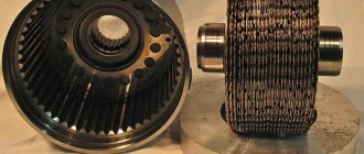
The design consists of alternating round plates that have inserts or perforations. The plates are mounted in a sealed drum and are located very close to each other. The drum is filled with silicone or dilatant fluid. When the two sets of plates rotate in unison, the fluid remains cool and in a liquid state. As the plates begin to rotate at different speeds, the effect of shifting the legs or perforations on the fluid causes the fluid to heat up and solidify. Silicone turns almost solid when heated, and the viscosity of dilatants also increases rapidly with differences in torque. The liquid, when solidified, “glues” the plates together and transfers power from one set to the next. The size of the tabs or perforations on the plates, as well as the number of plates used and the type of fluid determine the force and start time of the mechanical transmission.
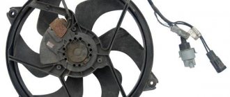
Viscous fan coupling,
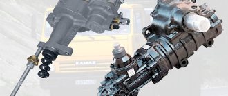
Viscous coupling device
The viscous coupling has a fairly simple structure and consists of a cylinder-shaped coupling with two shafts located inside it, which normally do not interact with each other. The driving and driven metal disks are directly attached to these shafts. They are located coaxially and are at a minimum distance. At the same time, there are quite a lot of them. It is worth noting that we schematically outlined the new generation viscous coupling. Its older version was a small hermetic cylinder with two shafts, on which two impellers were mounted. The shafts did not engage with each other. Knowing the device, you can easily guess the operating principle. For example, when a car with all-wheel drive is driving along a normal highway, rotation from the engine is transmitted only to the front axle. The shafts and disks of the viscous coupling rotate at the same speed, so there is no mixing of the oil in the housing.
Where are viscous couplings used?
Viscous couplings are used as a center differential in some four-wheel drive (4WD) vehicles such as the Toyota Celica GT-Four, and also as a limited slip differential (LSD) on rear axles. These units offer a cheaper way to implement all-wheel drive than the mechanically shifting Torsen differentials used by Audi.
Viscous coupling for Rolls Royce & Bentley
Volvo, Subaru, Land Rover, Vauxhall/Opel and many other brands used viscous couplings in their drives in the early stages of development. They are now being replaced by electronic devices.
Pros and cons of viscous coupling
Advantages:
- Fewer moving parts means less chance of breakdown and higher reliability.
- The speed of the powerplant is not directly related to driveshaft conditions (for example, the powerplant can continue to operate without stopping even if the transmission is stopped).
- Has the potential to temporarily increase torque output.
- Effective gear ratios can be easily changed by changing the nozzle diameter using Bernoulli's principle.
Viscous coupling for Kia Sorento
Flaws:
- There is always some slip between the two shafts, resulting in reduced efficiency.
- Limited application.
- More difficult to design and manufacture.
A little about the device
A viscous coupling is a device whose operating principle is the ability to transmit rotational motion through a special liquid that is pumped into it. It can be imagined as a small round chamber filled with silicone-based lubricant. There are two shafts inside this chamber, and the operating principle is as follows. The crankshaft performs a rotating motion, which is transmitted to the first clutch shaft. With increasing loads on the disk, its rotation speed becomes higher, this leads to an increase in the viscosity of the silicone inside the coupling.
The clutch is blocked, which leads to rotation of the second disk, on the shaft of which the radiator cooling fan is mounted. Another principle for turning on this device is the temperature properties of the pumped silicone grease. These properties are used to turn on the cooling fan when the engine temperature rises. As the temperature increases, it turns on, and when it decreases, it turns off.
The widespread use of couplings on modern engines is due to its high reliability and safety. If you handle it carelessly, if your hand gets into the rotation zone, it stops without damaging the hand.
Why is it needed and what kind of liquid is poured into the viscous coupling?
Fluid is pumped into the drive component using a power unit. It is then directed under pressure to the drive shaft. The pressure created in the fluid causes the drive shaft to move. At present, organopolysiloxane oils such as dimethylpolysiloxane or methylphenylpolysiloxane have been used as hydraulic fluid or working fluid for fluid couplings. Dimethylpolysiloxane (also called dimethylsilicone oil) has a high viscosity index and is widely used, but is difficult to maintain stable torque transmission capability over a long period under harsh operating conditions and high temperature. This is mainly due to the low thermal stability of this liquid.
Viscous coupling for Landcruiser
As operating conditions become more severe, it is optimal to choose silicone oil with improved thermal stability, which is 75% dimethyl silicone. To prevent oxidation or gelation, antioxidants (ferrous octanoate, phenylamine derivatives or ferrocene derivatives) are added to the organopolysiloxane oil.
How to check a viscous coupling?
A viscous coupling can fail in two main ways: shutting down completely, or remaining constantly on (sometimes only at higher operating rates). Fluid loss caused by leaking seals is the most likely cause of complete failure of a viscous coupling. Constant operation of a component indicates more complex damage and can lead to costly repairs. This can destroy the entire drivetrain, including the expensive transmission.
The main reasons for the atypical operation of the viscous coupling:
- Tires of different sizes and varying degrees of wear;
- Silicone fluid leaking, fan clutch disconnected.
- Natural wear under aggressive operating conditions and high operating temperatures.
- There is a drive mechanism that is not aligned correctly.
- The bimetallic sensor loses its properties due to surface oxidation, causing the coupling to become stuck.
- Bearing failure.
To check the viscous coupling, you need to install the rear wheels on a rack for tensile testing at a service center. If you shift to G-gear, the front wheels should lift the car off the test bench as soon as the engine drops slightly above idle. If the front wheels cannot do this, the viscous clutch must be replaced.
Replacing the viscous coupling
Required tools:
- Front Mounting Brackets: 17mm wrench and ratchet with extension.
- Case: 13 mm wrench with extension.
- Connections: Hex or 8mm socket with extension and ratchet.
- Drive shaft: two 13mm open wrenches (sometimes only 12mm for nuts).
Replacement procedure:
- Disconnect the hose and wash it under the viscous coupling housing.
- Raise the front of the car using a jack.
- a. Record and mark the driveshaft alignment of the front differential so you can place the same bolt through the same holes of each block when reassembling. This will reduce the chances of you unbalancing the driveshaft when reassembling.
3.b. Remove the four front bolts holding the driveshaft in place using a 13mm socket wrench. An alternative is to use a 1/2-inch open end wrench.
- Loosen the bolts holding the front differential in place so that it can be moved. Loosen the two bolts at the top rear of the diffuser that support it at the top, on the inverted "U" panel. Don't delete them. Remove the three mounting bolts here, one at the front, two at the back. Place a jack under the differential, at which time remove all bolts and fasteners.
- Slide the front diffuser forward until the drive shaft is disconnected from the front differential. Move the driveshaft to the side.
- Remove oil from the front diffuser through the oil drain hole. Recycle it. Before you remove the oil drain plug, make sure you can remove the oil fill plug.
- Remove the 13mm bolts holding the rear half of the front differential to the car, and then pull out the rear third of the differential. Also remove the 14mm bolts and two small copper washers near the top that connects the hose to the diffuser vent.
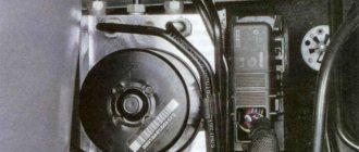
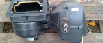
Repair of the viscous coupling of the Pajero radiator cooling fan.
This is what the removed fan looks like. Next, unscrew the three bolts and remove the impeller.
Then unscrew the three screws and remove the cover. The lid looks like this.
Carefully remove the disk located on top. As I understand it, this disk ensures blocking of the fan on the shaft. There is most likely a valve (bypass) on this disk! We remove the disk and see this oil painting
I WOULD LIKE TO PAY SPECIAL ATTENTION TO THIS!!! ALL THE LUBRICANT YOU SEE IN THE CLUTCH MUST BE SAVED!!! OTHERWISE THE ENTIRE REPAIR WILL BE USELESS!!!!! SAVE ALL LUBRICANT AS MAXIMUM!!! SINCE THIS IS NOT AN ORDINARY OIL, BUT SOME SILICONE SUBSTANCE THAT CHANGES ITS CHARACTERISTICS WITH CHANGES IN TEMPERATURE!!! WHEN THE TEMPERATURE INCREASES, IT BECOME VISCOUS, AND THE OIL, ON THE CONVERSE, IS LIQUID!! This is what it looks like without lube! During the repair, I unknowingly simply wiped it off with a rag L That's why I'll tell everyone once again: BE SURE TO SAVE THE LUBRICANT!!!
In order to press out a jammed bearing, you need to grind off the flaring on the shaft with something like a small machine bur. You can see what it looks like in the next photo!!
After grinding off the rolling on the shaft, we place the viscous coupling in a vice. More precisely, we spread the jaws of the vice so that the viscous coupling can be placed on top and it rests with its body (not the shaft) on the jaws! Attention!!! Under no circumstances should you hit the aluminum disk located on the shaft! If you bend it, you will ruin the viscous coupling!!! Then we put something strong, cylindrical, not much smaller than the diameter of the shaft, on the shaft, and with strong sharp blows we knock out the shaft! In order to press out the bearing, you need to do the following!! ATTENTION: the bearing in the seat is also rolled!!! You need to carefully either grind it off on a lathe or remove the wrapping with a burr machine. But so that the new bearing can be rolled! If you don’t grind off the rolling, the result will be like mine! Take a closer look at the photo and you will see that the housing is breaking off in pieces around the bearing!! It definitely needs grinding! Carefully!!
A bearing like the one in the viscous coupling costs about 40-60 rubles in the store, and it’s Japanese! It must be a closed type, that is, the balls should not be visible!!! You may need to apply sealant to the bearing seat just in case. And before it hardens, crimp the bearing and wipe off the excess sealant with a rag! The place where the bearing was rolled, either rolled or cored in a circle with a center punch! Then carefully press the shaft! Next, carefully press on the aluminum disk! We do this with a hammer! Give short blows through a wooden block (so as not to damage the disc) and roll it with something round! I did this using a ball from a large bearing!
That's all! Add the lubricant that you carefully collected. We put the steel disk on the marks! These are the indentations on the disc and the fan viscous coupling housing!
Author: strange-tm, pajero4x4.ru
Replacing the viscous coupling bearing
To determine if the bearing needs to be replaced, remove the auxiliary belt. Turn the fan. If the viscous coupling moves, replace only the gasket. If the pulley moves, then it's time to change the bearing.
To remove the bearing, first remove the viscous coupling. After removing the component you will see the front ring. Take it off. Place one washer on the 5-inch bolt and slide it to the back of the bearing. Place the pipe coupling on the other side. Place the flange over the coupling with the raised part inside. Make sure the socket you use on the nut will fit inside. Place one washer on the bolt followed by the socket. Then put on a small washer and nut.
If a bolt is crooked, stop and straighten it. Attach the bolt and begin tightening. The bearing housing will be clogged. Clean it as best you can. Now place a 4-inch bolt into the back of the new bearing, followed by a washer. Place the nut and press it lightly. Make sure it is facing the correct direction. Warm up the case. Without a bearing, it will heat up quickly. Wear leather gloves. Insert the bearing into the groove.
Stages of truck viscous coupling repair
In most cases, viscous coupling malfunctions are associated with leakage of silicone substance. In such situations, the device must be dismantled. Having removed the viscous coupling, remove the pulley and pour out the remaining emulsion. Most cases have a special drain hole. If there is no hole, a new one is made independently.
It is important to know! Do not mix old silicone fluid with new one. This may damage the viscous coupling.
The new silicone mixture is poured through a syringe. The viscous coupling is designed for a minimum volume of 15mG. This is done with short pauses, as the liquid must spread between the disks for even distribution.
Another common cause of cooling clutch failure is a broken bearing. This breakdown can be identified by the characteristic sound emanating from the fan.
In this case, it is also necessary to dismantle and drain the liquid. The process of replacing a bearing is very complicated in road conditions, since its implementation requires:
- puller
- new silicone liquid
- master's experience
24 Volt specialists have everything necessary to replace and repair the cooling clutch.
Electric fan instead of viscous coupling. Is it worth it?
An electric fan is a thermostatic engine cooling fan that can spin freely at low temperatures when cooling is not needed, allowing the engine to warm up faster, removing unnecessary stress on the engine. As the temperature increases, the clutch engages so that the fan is driven by engine power and moves air to cool the engine.
An electronically controlled fan is a device in which the output drive to the fan is controlled by electronically moving viscous fluid from a fluid reservoir to the clutch operating chamber during normal operation. A radially balanced valve disc coupled to a spring controls the relative movement of viscous fluid from the fluid reservoir to the process chamber by sealing and disengaging the fill orifice. The clutch plate, cover and housing, along with the functions, are molded to the required size and shape, making electric fans easier and more accurate to manufacture than traditional viscous coupling designs.
Mechanical fans are most common in trucks and SUVs, as well as some four-wheel drive vehicles. This is easier to do because the engine is mounted longitudinally and the auxiliary belt components are mounted on the radiator. The fan mounts on the crankshaft pulley or one of the accessory pulleys (such as a water pump pulley) and will rotate between the radiator and engine, drawing air through the radiator and blowing it over the engine.
In contrast, in a front-wheel drive vehicle, the engine is typically mounted to the side of the crankshaft and all main auxiliary shafts parallel to the front axle drive the transmission. The fan, mechanically mounted on the auxiliary pulley, will be located on the side and will not face the radiator. This is why electric motor driven fans are used almost universally in front wheel drive vehicles. Converting mechanical energy to electricity and back to mechanical rotational power with a fan motor is less efficient than a direct mechanical connection, but this is more than compensated for by the greater control of the electric fan through electronic thermostatic controls that can shut off the fan completely when the motor temperature is below a set point.
Operating principle of radiator cooling fan viscous coupling
How does the Toyota fan viscous coupling work and what is its operating principle? Since this topic still sometimes raises questions, let’s try to figure it out...
Operating principle of viscous coupling
A belt-driven fan, usually combined with a coolant pump, has traditionally been installed on most models with a longitudinal power unit. If the fan impeller was rigidly connected to the drive pulley, then its rotation speed was directly proportional to the crankshaft speed - such cooling would be excessively effective, especially at high speeds and at low temperatures outside. Therefore, to regulate the intensity of the air flow passing through the radiator, a viscous coupling is installed between the pulley and the impeller.
At low temperatures, the fan rotation speed is minimal, which allows the engine to warm up faster and at the same time reduces noise from the impeller. As the temperature rises, the fan speed will also increase.
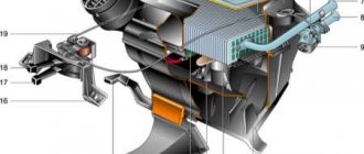
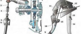
Design of viscous cooling fan coupling
The viscous coupling rotor is rigidly mounted on the coolant pump pulley. There are oblique teeth cut around the circumference of the rotor disk, which act as a pump for pumping oil. The viscous coupling housing assembly (bearing housing and front cover) rotates around the rotor on a bearing.
There are plates installed on both sides of the rotor that separate the working chambers from the reservoirs. The front one (with inlet ports A and B and the return port) is mounted on the rotor cover, the rear one (with the return port) is mounted on the bearing housing.
1 - bimetallic spring, 2 - bimetallic plate, 3 - inlet channel B, 4 - inlet channel A, 5 - front chamber, 6 - return channel, 7 - return channel, 8 - rear chamber, 9 - front reservoir, 10 - teeth rotor, 11 — bearing housing, 12 — rotor shaft, 13 — bearing housing, 14 — rear reservoir, 15 — rear dividing plate, 16 — rotor, 17 — front dividing plate, 18 — front cover.
The working chambers are “labyrinths” formed by ribs on the rotor and on the dividing plates. The torque is transmitted from the rotor to the housing due to “internal friction” in silicone oil.
A bimetallic spring installed on the outside of the viscous coupling body moves the plate, opening and closing the inlet channels and regulating the flow of oil depending on the air temperature.
Operation of the radiator viscous coupling
Viscous coupling, Cold air.
As the rotor rotates, its teeth “pump” oil from both chambers and the rear reservoir into the front reservoir through the return channels. As a result, its quantity in the chambers decreases, the transmission of force through the liquid decreases and the fan rotation speed becomes significantly lower than the rotation speed of the main rotor.
Viscous coupling, Warm air.
Centrifugal force forces the oil from the front reservoir into the front chamber through the opened inlet port A. The “viscous friction” between the rotor and the front plate increases and the difference in speed decreases.
Viscous coupling, Hot air.
Both inlet channels open, after which oil enters both working chambers. The volume of fluid in them and the “friction” are maximum, so the transmission of rotation through the viscous coupling is also maximum.
Note. Since speed control occurs by changing the volume of silicone oil in the cavities of the viscous coupling, its leakage inevitably leads to a decrease in fan speed and possible engine overheating.
Some viscous couplings of the early design did not have a rear reservoir. Since after stopping the engine the oil flows into the lower part of the viscous coupling, here its level in the chambers increased significantly and immediately after starting the engine, when the “friction” between the rotor and the plates was sufficiently large, the fan speed increased too much. If there is a rear reservoir, the fluid level in the chambers is lower when the engine is stopped, and after starting it drops faster - as a result, the noise level from the fan is reduced.
Evgeniy E., Moscow (c) “Legion-Avtodata”