What you need to properly tighten your wheel bolts
Many people often wonder how hard they can tighten wheel nuts at home. This process seems quite simple at first glance. Before starting a step-by-step action, a person must prepare certain tools. Very often, car owners independently perform these actions at home and, without counting their strength, break the thread. This is due to the beginner putting enough pressure on the bolts.
Bolt tightening process
The tightening torque of the wheel bolts is carried out with the preparation of the necessary tools. To perform the process correctly, you need to purchase a special torque wrench. Without this tool it is difficult to imagine the process of tightening bolts.
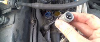
As a rule, a pneumatic impact wrench regulates the tightening torque of elements on a structure. If a bolt that is not tightened protrudes from the front, then discomfort will be felt while moving on the vehicle. That is, the car will “shake” a little. After all, the main load falls on the steering wheel.
Torque Wrench Bolt Torque Chart
Recently, many car owners have been installing lightweight alloy wheel nuts made of aluminum. They look stylish.
A special table of the tightening force of these wheel bolts depending on the manufacturer and model will allow you to determine all these parameters.
Vehicles require constant care and careful checking of all components. When performing the inspection, it is necessary to monitor the performance of mechanisms and electrical systems. Wheel bolts also require periodic maintenance and lubrication with high-quality compounds.
The process of tightening wheel bolts: step-by-step steps
To ensure that the structures are securely fixed with the required torque, there is a special table for tightening the bolts with a torque wrench. For example, if there are four of them (1-3-4-2), 5 bolts (1-4-2-5-3) or 6 bolts (1-4-5-2-3-6).
The process itself is carried out as follows:
- You need to put the wheel on the protrusion of the central part of the hub, and place the guide pins opposite the corresponding holes.
- Next, you will have to manually tighten the bolts tightly enough so that the wheel does not jump out of place.
- After completing all the steps, you need to take the tool with the set torque and tighten the wheels in the correct order.
Practical application: how to use the tool correctly
Indicator devices do not cause any difficulties. You just read the readings and see the torque. But the click mechanism requires getting used to and correct understanding of the scale markings. Rough readings are marked on the fixed shaft of the handle. Precise divisions on the turning part.
The illustration shows marks at 98 Nm and 2 Nm (on the rotary handle). The values are added up: the final value is 100 Nm. To tighten the car wheel bolts with such a torque wrench (for example, a value of 120 Nm), you need to set 112 Nm on the fixed handle and 8 Nm on the rotating part.
If you understand the general principle, using the tool will be convenient.
There are various marking options:
In what order should the wheel nuts be tightened?
The nuts are pulled crosswise. To make it more clear, look at the attached image below:
That's all for today. If anyone has questions, thoughts, additions, you are welcome to comment. As always, they are open, waiting for questions and discussions.
A certain degree of tightening of threaded elements is carried out in order to increase service life, strength and increase resistance to various influencing factors. For each fastener there is a certain degree of tightening at each seat; it is calculated based on loads, temperature conditions and material properties.
For example, when exposed to temperature, metal tends to expand; under the influence of vibration, the fastener receives additional load, and in order to minimize it, it must be tightened with the correct force. Let's consider the tightening force of the bolts, tables, methods and tools for carrying out the work
Useful tips
The driver is required to check the condition of the wheels before starting work and after finishing the shift.
• Check what can be seen with the naked eye: there are no distortions, runout, misalignment; Is the tire pressure sufficient? does the wheel rub against other parts of the car - frame, fender?
Look for signs of uneven wear on the tread or sidewalls, bubbles due to broken cords, and other defects. Are different tires installed in a pair, are all valve caps in place?
• Pay attention to any oil or fuel leaks - these fluids can damage your tires. • Check that the rims are not bent or otherwise damaged, and that there are no signs of the tire turning relative to the rim
• Check that the rims are not bent or otherwise damaged, and that there are no signs of the tire turning relative to the rim.
• All axles and wheels must be located (rotate) in the correct planes, and suspension movements must also be made in the correct planes. Deviations can cause tires to slip and slip, which, of course, shortens their service life, creates additional rolling resistance and increases fuel consumption.
• Remove any objects stuck in the tread and between the dual tires.
• Inspect tires that have cuts or other defects. Off-road tires often have damage, but they are not always dangerous and impair its performance. If the damage is really serious, the tire should be replaced or repaired. Contact qualified technicians who can determine whether the damaged tire can be repaired or should be replaced. You can fill as many nail holes as you like. There should be no more than two cuts. A hole in the tread pattern area of no more than 10 mm in length is allowed. Repair options in the most stressed areas of the sidewalls are also limited.
• Do not weld or otherwise heat the rims near a mounted tire. Be sure to remove tires before performing heat-related wheel repairs.
• Before removing the inner or outer wheel rim, both dual tires must be deflated.
• It is forbidden to lift tires with a crane, securing the hook from the inside to the sidewall. Use flat straps that wrap around the outside of the tire.
• Do not install damaged tires or wheels on steering axles.
• Tires should be replaced in advance. It is not profitable to operate tires until the groove depth reaches the maximum value. It is recommended to leave approximately 5 mm of the pattern to the maximum depth so that the tire can be repaired by welding.
• Store tires in a cool, dry place, out of direct sunlight, and in an upright position rather than stacked.
Marking of parts
This parameter is indicated on the bolt head. For parts made on the basis of carbon steel with strength class 2, numbers are indicated through a dot, for example: 3.5, 4.8, etc.
The first digit indicates 1/100 of the nominal tensile strength size, measured in MPa. For example, if the bolt head says 10.1, then the first number means 10*100 = 1000 MPa.
The second figure is the ratio of yield strength to strength, multiplied by 10, according to the above example - 1 * 10 * 10 = 100 MPa.
The yield strength is the maximum load on a bolt. For elements made of stainless steel, steel type A2 or A4 is applied, and then the tensile strength. For example: A4-40. The number in this marking characterizes 1/10 of the tensile strength of carbon steel.
The main disadvantages and weaknesses of the 10th generation Toyota Corolla (E140)
Weaknesses of Toyota Corolla 2006–2013 release
Now more details...
Robotic gearbox.
It is the “robot” in Corollas of this body that causes many problems. Therefore, before purchasing, it is imperative to weigh the pros and cons when choosing a car of this model with a robotic gearbox. “Kicking” and jerking when switching give a signal that the operation of this unit is disrupted.
If you do not pay attention to this, then one of the following situations is possible - the neutral gear will engage and the gear icon will light up on the instrument panel. And accordingly, this means the “end” of the “robot’s” life. And it is important to remember that if the “robot”, like another box, fails, you will have to pay a decent amount of money.
If the choice fell on a car with a “robot”, then it is very necessary to seriously assess the condition of the box.
Sore spots in the suspension.
In general, we can say that the suspension of this Toyota model is difficult to reduce to a deplorable state. But there are weaknesses here too. First of all, these are stabilizer struts and bushings. These are not critical faults that appear in the region of 78-80 thousand km, but it is worth paying attention to them.
Steering rack.
One of the common problems with Toyota Corolla is the steering rack bushing. The bushing itself is plastic and wears out quickly, as can be evidenced by knocking on the steering wheel when driving even over minor road unevenness. However, the steering rack itself does not pose any problems and can serve for a long time.
Bendix starter.
One of the troubles can be caused by the starter bendix. But it is important to remember the peculiarity that this happens en masse only when the mileage approaches one hundred thousand, but there have been cases at 50-60 thousand km. Signs of a bendex malfunction are: the car starts every once in a while or a whirring sound without cranking with the flywheel catching.
Water pump.
This breakdown occurs within 100 thousand km. vehicle mileage. Considering that, according to statistics, the 10th generation Corolla, even the latest years of production, should already “run” in the region of 80-100 thousand km. You need to pay attention to this when purchasing. A characteristic sign that the pump is approaching the end of its life is an unpleasant noise coming from under the hood.
Disadvantages of the 10th generation Toyota Corolla
Conclusion.
In general, we can say that the Toyota Corolla has more positive aspects than weak points and shortcomings.
The main thing before purchasing is to decide which engine and gearbox to buy the car with and to take the check and inspection of the car upon purchase with full responsibility.
Remember that better diagnostics of the car you are buying can be done at specialized car services, which in the future will help you save a decent amount of money to eliminate breakdowns and malfunctions caused by the previous owner.
Dear owners of the tenth generation Toyota Corolla! Write to x about problem areas of your Corolla identified during operation.
The main disadvantages and weaknesses of the 10th generation Toyota Corolla (E140) was last modified: November 8, 2021 by Administrator
Tightening torques for threaded connections
Below is a table for tightening bolts using a torque wrench.
| Bolt strength, in Nm | |||
| Thread size | 8.8 | 10.9 | 12.9 |
| M6 | 10 | 13 | 16 |
| M8 | 25 | 33 | 40 |
| M10 | 50 | 66 | 80 |
| M12 | 85 | 110 | 140 |
| M14 | 130 | 180 | 210 |
| M16 | 200 | 280 | 330 |
| M18 | 280 | 380 | 460 |
| M20 | 400 | 540 | 650 |
Toyota Corolla E150 (2010+). TIGHTENING TORQUES OF RESPONSIBLE THREADED CONNECTIONS
| Mating Parts | Tightening torque, N m |
| Engine | |
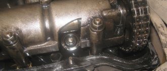
| Right Engine Mount Bracket - Timing Chain Cover | 52 |
| Right engine mount bracket - cylinder block | 54 |
| Movable engine rack with bracket - right engine mount bracket | 64 |
| Movable engine rack with bracket - right wing apron | 64 |
| Right engine mount - cylinder head | 64 |
| Right engine mount - right engine mount bracket | 64 |
| Engine Hanging Hook - Cylinder Head | 43 |
| ECT Sensor - Cylinder Head | 20 |
| Knock Sensor - Cylinder Block | 21 |
| Contact Oil Pressure Switch Assembly - Cylinder Head | 15 |
| Coolant Temperature Sensor - Cylinder Head | 20 |
| Coolant bypass pipe - cylinder block | 21 |
| Oil cooler pipe - cylinder block | 9 |
| Right engine mount bracket - cylinder block | 54 |
| Drive Shaft Bearing Bracket - Engine Block | 64 |
| Belt Tensioner Assembly - Timing Chain Cover | 60 |
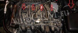
| Ignition coil assembly - cylinder head | 10 |
| Engine cover - cylinder head cover | 10 |
| Exhaust manifold - cylinder head | 21 |
| Air pipe - cylinder head cover | 10 |
| Exhaust Manifold Support - Exhaust Manifold | 43 |
| Exhaust Manifold Heat Shield - Exhaust Manifold | 12 |
| Oil Level Sensor Guide - Cylinder Block | 21 |
| Intake manifold - cylinder head | 28 |
| Drive Disc and Ring Gear (Automatic Transmission Models) - Crankshaft | 98 |
| Flywheel assembly - crankshaft | 49 |
| Left engine mount - body | 56 |
| Left engine mount - manual transmission assembly | 143 |
| Right engine mount mounting nut - right engine mount bracket | 95 |
| Right deignator support pad - frame: nut bolt | 52 95 |
| Front Engine Mount - Front Engine Mount | 145 |
| Front cross member - body | 96 |
| Clutch Slave Cylinder Assembly - Transmission | 12 |
| Battery area - body | 19 |
| Coolant pipe - battery pad | 19 |
| Rear Engine Mount Bracket - Engine Traverse Control Rod (Manual Transmission Models) | 89 |
| Cylinder head - cylinder block | 49 + tighten by 90″ + tighten by 45° |
| Camshaft drive sprocket - camshaft | 54 |
| Camshaft Bearing Cap - Cylinder Head | 27 |
| Camshaft Bearing Cap - Cylinder Head | 9 |
| Oil pump assembly - crankcase with stiffeners assembly | 19 |
| Oil pump drive sprocket - oil pump | 30 |
| Mating Parts | Tightening torque, N m |
| Chain tensioner plate - crankcase with stiffeners assembly | 12 |
| Chain Guide - Cylinder Head | 9 |
| Chain Guide - Cylinder Block | 21 |
| Chain Tensioner Shoe - Engine Block | 19 |
| Timing Chain Guide - Crankshaft Bearing Cover | 9 |
| Oil pan - crankcase with stiffeners assembly | 9 |
| Oil pan drain plug - oil pan | 37 |
| Coolant drain valves - cylinder block | 20 |
| Coolant drain plug - coolant drain valves | 13 |
| Camshaft housing - cylinder block | 27 |
| Generator bracket - cylinder block | 21 |
| Coolant Inlet Housing - Timing Chain Cover | 9,1 |
| Hydraulic camshaft valve - cylinder head cover | 10 |
| Timing chain cover - cylinder block, cylinder head: bolt A bolt B bolt C nut | 9 25 55 11 |
| Crankshaft Position Sensor - Timing Chain Cover | 10 |
| Crankshaft Pulley - Crankshaft | 190 |
| Chain Tensioner - Timing Chain Cover | 10 |
| Camshaft Position Sensor - Cylinder Head Cover | 10 |
| Radio Tuning Capacitor - Cylinder Head | 10 |
| Cylinder head cover - cylinder head | 10 |
| Cylinder head cover - engine wiring harness | 8,4 |
| Oil filter fitting - crankcase with stiffeners assembly | 30 |
| Oil filter fitting - crankcase with stiffeners assembly: oil filter fitting nut hollow connecting bolt fitting | 79 9 25 |
| Oil filter - oil filter fitting | 25 |
| Spark plug - cylinder head | 20 |
| Breather - cylinder block | 20 |
| Stud - crankcase | 5 |
| Stud - cylinder head: bolt A bolt B bolt C bolt D | 5 5 9.5 9.5 |
| Screw plug - cylinder head | 44 |
| Stud - cylinder block: bolt A bolt B bolt C bolt D | 22 5 9,5 5 |
| Crankshaft Bearing Cap - Cylinder Block | 40 + turn 90° |
| Connecting rod cover - connecting rod | 20 + turn 90° |
| Supply system | |
| Fuel rail assembly - cylinder head assembly | 21 |
| Fuel tank assembly - body | 39 |
| Exhaust system | |
| Downpipe Assembly - Center Exhaust Pipe Assembly | 43 |
| Mating Parts | Tightening torque, N m |
| Reception pipe assembly - exhaust manifold | 43 |
| Center exhaust pipe assembly - rear exhaust pipe assembly | 43 |
| Exhaust manifold - cylinder head assembly | 21 |
| Manifold strut - cylinder block assembly | 43 |
| Exhaust Manifold Heat Shield - Exhaust Manifold | 12 |
| Transmission | |
| Clutch pedal stop bolt - lock nut | 16 |
| Clutch master cylinder rod fork locknut | 12 |
| Clutch Pedal Assembly - Clutch Pedal Bracket | 37 |
| Clutch Pedal Switch Assembly - Clutch Pedal Bracket | 16 |
| Clutch Switch Assembly - Clutch Pedal Bracket | 16 |
| Clutch pedal bracket - body | 24 |
| Clutch Master Cylinder - Clutch Pedal Bracket | 13 |
| Clutch Line - Clutch Master Cylinder | 14 |
| Clutch slave cylinder bleeder - clutch slave cylinder | 8,3 |
| Clutch Slave Cylinder - Manual Transmission Housing | 12 |
| Clutch Pipe - Clutch Slave Cylinder | 14 |
| Clutch housing assembly - flywheel assembly | 19 |
| Clutch release fork support - manual transmission | 37 |
| Clutch drive - gear selection and shift drive | 17 |
| Fill Plug - Manual Transmission Housing | 39 |
| Drain Plug - Manual Transmission Housing | 39 |
| Gear shift lever assembly - body | 12 |
| Shift Cable - Body | 5,5 |
| Rear Engine Mount Bracket - Manual Transmission Assembly | 45 |
| Front Engine Mount Bracket - Manual Transmission Assembly | 64 |
| Left Engine Mount Bracket - Manual Transmission Assembly | 64 |
| Shift Cable Bracket - Manual Transmission Assembly | 25 |
| Manual transmission assembly - engine (1ZR-FE) | 33 |
| Shift Fork - Shift Fork Rod | 16 |
| Reverse gear lever bracket - transmission housing | 17 |
| Transmission housing - transmission housing in a block with the main gear | 29 |
| Reverse Idle Gear Shaft Bolt - Transmission Housing | 29 |
| Transmission Output Shaft Rear Nut - Output Shaft | 118 |
| Transmission Housing Cover - Transmission Housing | 18 |
| Drive Shaft Cover - Transmission Housing | 20 |
| Shift Pin - Transmission Housing | 11 |
| Ball retainer #1 - transmission housing | 29 |
| Shift Lever Damper - Selector and Shift Lever Shaft Assembly | 12 |
| Floor Shift Lever - Selector and Shift Lever Shaft Assembly | 12 |
| Gear Selector Crank Assembly - Transmission Housing for Bolt | 25 |
| Gear Selector Crank Assembly - Transmission Housing for Nut | 12 |
| Floor Shift Lever Drive Shaft Assembly - Selector Crank Mount | 12 |
| Reverse Light Switch - Transmission Housing | 40 |
| Speedometer drive cover - transmission housing | 11 |
| Front Differential Ring Gear - Front Differential Housing | 77 |
| Mating Parts | Tightening torque, Nm |
| Chassis | |
| Front wheel nuts | 103 |
| Rear wheel nuts | 103 |
| Steering knuckle - front lower control arm | 89 |
| Steering knuckle - front wheel hub assembly | 96 |
| Steering knuckle - front/disc brake caliper | 107 |
| Front Shock Absorber with Coil Spring Assembly - Steering Knuckle | 240 |
| Steering Knuckle - Front Lower Ball Joint | 133 |
| Steering knuckle - tie rod end | 49 |
| Front Drive Shaft - Front Wheel Hub Nut | 292 |
| Rear disc brake caliper assembly - rear suspension knuckle assembly | 57 |
| Rear wheel hub with bearing assembly with rear speed sensor - rear suspension knuckle assembly | 90 |
| Rear suspension trailing arm - rear suspension knuckle assembly | 200 |
| Rear Suspension Arm Assembly - Rear Suspension Knuckle Assembly | 90 |
| Coil Spring Front Shock Absorber - Body | 50 |
| Coil spring front shock absorber - front cam | 240 |
| Front shock absorber nut | 47 |
| Front Speed Sensor Wire - Front Shock Absorber | 29 |
| Coil Spring Front Shock Absorber - Front Stabilizer Link | 74 |
| Front suspension cross member - rear engine mount | 95 |
| Front suspension cross member - body | 145 |
| Front suspension rear bracket - body: bolt A bolt B | 145 93 |
| Strengthening the front suspension element - suspension element | 96 |
| Lower reinforcement of the front bracket of the deigator support - suspension element | 96 |
| Front Stabilizer Link - Front Anti-Roll Bar | 74 |
| Front suspension lower arm - front suspension cross member | 233 |
| Front Lower Ball Joint - Steering Knuckle | 133 |
| Front Lower Ball Joint - Front Lower Control Arm | 89 |
| Front Suspension Bracket - Front Suspension Crossmember | 87 |
| Rear shock absorber - rear suspension arm | 90 |
| Nut securing the rear support to the rear shock absorber - rear shock absorber | 25 |
| Rear suspension arm No. 2 - rear stabilizer link | 30 |
| Rear Anti-Roll Bar - Rear Anti-Roll Bar Link | 95 |
| Rear Suspension Upper Arm - Rear Suspension Knuckle | 90 |
| Rear suspension upper arm - rear suspension element | 90 |
| Rear suspension arm No. 1 - rear suspension knuckle | 100 |
| Rear suspension arm No. 2 - rear suspension knuckle | 90 |
| Rear suspension trailing arm - rear suspension knuckle | 200 |
| Rear suspension trailing arm - body | 90 |
| Brake system | |
| Brake pedal bracket - instrument panel reinforcement | 24 |
| Brake Pedal Bracket - Brake Booster Assembly | 13 |
| Brake Pedal Bracket Assembly - Brake Pedal | 37 |
| External upper panel of the casing - body | 8,8 |
| Brake pipe | 14 |
| Brake pipe - body | 8 |
| Brake Master Cylinder - Brake Booster Assembly | 13 |
| Disc Brake Wheel Cylinder Assembly - Front Disc Brake Wheel Cylinder Bracket | 34 |
| Mating Parts | Tightening torque, N m |
| Front Disc Brake Wheel Cylinder Bracket - Steering Knuckle | 107 |
| Front disc brake bleeder | 8,3 |
| Front Flex Hose - Disc Brake Cylinder Assembly | 29 |
| Front Flex Hose - Front Shock Absorber Bracket | 29 |
| Front Flex Hose - Brake Line | 14 |
| Rear Disc Brake Cylinder Assembly - Rear Disc Brake Caliper | 34 |
| Rear disc brake bleeder | 11 |
| Rear Flex Hose - Rear Disc Brake Wheel Cylinder Assembly | 29 |
| Rear Brake Flex Hose - Brake Line | 14 |
| Mating Parts | Tightening torque, N m |
| Parking brake switch installation nut assembly | 0,9 |
| Parking brake cable locknut assembly | 6 |
| Parking brake lever assembly installation bolts | 15 |
| Steering | |
| Intermediate Steering Shaft - Steering Column Assembly | 35 |
| Steering column mounting nuts | 25 |
| Steering Column Installation Bolt | 25 |
| Steering wheel mounting nut | 50 |
| Intermediate Steering Shaft - Tie Rod Assembly | 35 |
| Tie Rod End Assembly - Steering Knuckle | 49 |
| Tie rod end locknuts | 74 |
Toyota Corolla E150 (2010+). Fuel and lubricants, special liquids and refilling volumes
| Filling/lubrication point | Volume gas stations | Name material/liquid |
| Fuel tank (vehicles with engines 1NR-FE 1.3 l, 4ZZ-FE 1.4 l, 1ZR-FE 1.6 l | 55 | Unleaded gasoline with an octane rating of at least 95 |
| Engine lubrication system (including oil filter) engines: 1NR-FE (1.3 l) 4ZZ-FE (1.4 l) 1ZR-FE (1.6 l) | 3.4 l 4.2 l 4.2 l | Oil type SAE 0W-30, 5W-40. ACEA class: AZ, VZ, B4; by API: SL/CF |
| Engine cooling system: 1NR-FE (1.3 l) 4ZZ-FE (1.4 l), 1ZR-FE (1.6 l) | 5.7 l 6.0 l | Toyota Super Long Life Antifreeze Coolant or similar |
| Five-speed manual transmission | 1.9l | Oil type: Toyota Synthetic Gear Oil. SAE 75W-90. no API class: GL4/GL5 |
| Six-speed manual transmission | 2.3 l | Same |
| Automatic transmission | 2.9 l | Toyota WS |
| Hydraulic brake system for vehicles with engines 1NR-FE (1.3 l), 4ZZ-FE (1.4 l), 1ZR-FE (1.6 l) | DOT-4 brake fluid | |
| Clutch release bearing spline | Toyota Clutch Spline Grease or equivalent | |
| External constant velocity joints of front wheel drives | 91-111 g | Special lubricant type CV joint-4, CV joint-4M or similar |
| Internal constant velocity joints of the front wheel drives of vehicles with engines 1NR-FE (1.3 l), 4ZZ-FE (1.4 l), 1ZR-FE (1.6 l) | 125-135 g | Same |
Toyota Corolla E150, Auris. SPARK PLUGS USED ON A CAR
| Engine | Spark plug | Gap, mm |
| 1NR-FE (1.3 l) | DENSO SC20HR11 | 1,0-1,1 |
| 4ZZ-FE (1.4 l) | DENSO K16R-U11 | 1,0-1,1 |
| BOSCH HFR8KCU | 0,9-1,0 | |
| 1ZR-FE(1.6 l) | DENSO SC20HR11 | 1,0-1,1 |
Toyota Corolla E150, Auris. TIRE AIR PRESSURE, kPa Appendix 4
| Tire size | At speeds up to 160 km/h | At speeds over 160 km/h | ||
| front | rear | front | rear | |
| 195/65 R15 91H, 205/55 R16 91V | 220 | 220 | 250 | 250 |
Toyota Corolla E150 (2010+). LAMPS USED ON VEHICLES
////////////////////////////
Tightening torques for band clamps with worm clamps
The table below provides information for initial installation on a new hose, as well as for re-tightening an already crimped hose.
| Clamp size | Nm | lb/in |
| 16mm - 0.625 inches | 7,5±0,5 | 65±5 |
| 13.5mm - 0.531 inches | 4,5±0,5 | 40±5 |
| 8mm - 0.312 inch | 0,9±0,2 | 8±2 |
| Tightening torque for re-tying | ||
| 16mm | 4,5±0,5 | 40±5 |
| 13.5mm | 3,0±0,5 | 25±5 |
| 8mm | 0,7±0,2 | 6±2 |
DIY torque wrench
- old ratchet wrench
- 10 mm hex key.
- two 8 mm nuts.
- scales with a digital dial up to 40 kg. (bought here)
- piece of strip 4*40 mm
- welding machine
- Angle grinder (grinder)
- pliers, hammer, file and other plumbing tools.
From the school physics course we know: 1 N (Newton) = 0.1019716212978 kg. 1 kg. = 9.806649999999 N (Newtons).
The tightening torque can be calculated using the following formula: kgf•m = m / (1 / L) where: kgf•m – kilogram of force per meter (force applied in kilograms) m – scale readings L – arm length in meters (distance from the center of the bolt before attaching the scales)
To convert the applied force into Newtons you need: N•m = kgf•m * 9.81 where: N•m – Newton per meter kgf•m – kilogram per meter of force
Most often, the tightening torque is written in Newtons, but our DMK shows the force in kilograms. For example, I need to tighten the nut with a force of 20 N. In order to find out what readings should be on the scales, we will use the formula
: m = Н * 0.102 * (1 / L) where: m – scale readings Н – tightening torque with which the threaded connection needs to be tightened L – arm length in meters (distance from the center of the bolt to the scale mounting).
m = 20 * 0.102 * (1 / 0.114) = 17.89 kg.
It follows that in order to tighten the nut with a force of 20 N, the scale should read 17.89 kg.
I made a small table in Excel with formulas, you can download it here. For convenience, you can create a table with the required values, then you will not need to calculate each time.
Conclusion Of course, this key is not suitable for use at a service station, but for the home it’s not bad at all. The characteristics of this key are not great. The shoulder is 11.4 cm, the maximum tightening torque is 4.5 kg or 44 N. These characteristics can be improved by changing the size of the key or installing more powerful scales. I collected this key from what I had. I hope you liked this homemade product.
Delivery of new homemade products by mail Receive a selection of new homemade products by mail. No spam, only useful ideas!
*By filling out the form you agree to the processing of personal data
Become the author of the site, publish your own articles, descriptions of homemade products and pay for the text. Read more here.
How to determine the tightening torque
- Using a torque wrench.
This tool should be selected in such a way that the tightening torque of the fastener is 20-30% less than the maximum torque on your wrench. If you try to exceed the limit, the key will quickly fail.
The tightening force and type of steel are indicated on each bolt; how to decipher the markings was described above. For secondary broaching of bolts, several rules must be taken into account:
- Always know the exact tightening force required.
- When checking the tightening, it is worth setting the force and checking all the fasteners in a circular order.
- It is forbidden to use a torque wrench as a regular one; it cannot be used to tighten parts, a nut, or tighten a bolt to the approximate force; control pulling is done with a torque wrench.
- The torque wrench must be spared.
- Without torque wrench.
To do this you will need:
- Socket or open-end wrench.
- Spring canter or scale, with a limit of 30 kg.
- A table indicating the tightening force of the bolts and the tightening torque of the nuts.
The tightening torque is the force applied to a lever measuring 1 meter. For example, we need to tighten the nut with a force of 2 kgf/m:
- We measure the length of our spanner; for example, it was 0.20 meters.
- Divide 1 by 0.20 to get the number 5.
- We multiply the results obtained by 5 by 2 kGf/m and ultimately get 10 kg.
Moving on to practice, we take our key and scales, attach the hook to the key and tighten it to the desired weight, according to the calculation described above. But even this method will ultimately turn out to be better than pulling from “hand to eye”, with an error, the higher the effort, the smaller it is. This will depend on the quality of the scales, but it is better to purchase a special key.
Replacing rear shock absorbers (photo report) on a Toyota Corolla E120 (left-hand drive)
The time has come to replace the rear shock absorbers; suspicious and unpleasant sounds from the suspension have long been present, and there is no smoothness during movement. When driving off a curb, for example, the car sagged a lot, as if it was hanging on only by springs (in principle, it was).
There was nothing suitable in the city stores (the store had KYB for 1850, but the purchases were not carried out on the database at the time, and the next day they were no longer there, what a bummer :-().
The stores offer TOKIKO made in China for 2000 rubles and many other things Made in China.
As a result, we purchased at the existential: Gas suspension shock absorber, rear “Excel-G” Kayaba 341816 costing 2,384.80 each, total for two: 4,769 rubles 60 kopecks.
Kayaba suspension shock absorber "Excel-G" 341816
How to identify fake Kayaba or not?
Shock absorbers KYB 341816 are made in Spain Made in Spain. While I was choosing what to install, I learned how to detect a fake KYB, and that one range of shock absorbers is produced only at one plant.
That is, Kayaba 341816 shock absorbers are produced only at a factory in Spain; if production in another place is written on the shock absorber, then it is a fake, although the place of production is usually not written on fakes and the name of the shock absorber will only be on stickers. Usually only the nomenclature is stamped on the counter on a fake.
Well, accordingly, on the original KYB racks, all welds are neat, the name is stamped on the rack. In general, the original is in the photo above.
Preparing the car for replacing rear shock absorbers
First of all, before replacing the rear shock absorbers, I put the car on wooden blocks, dismantled the trim in the trunk and filled the lower nut with a liquid wrench (similar to WD-40).
Since the bottom nut is exposed to all the elements, it is a little rusty. To unscrew it, I set the key to 19 and rested it with a jack.
After briefly tapping the nut with a hammer, it gave way and was safely unscrewed, also on the second side.
Unscrew the lower nut securing the rear shock absorber
Next, you need to loosen the shock absorber rod nut; to do this, insert a hex key into the end of the rod and use a spanner to remove the nut.
Loosen the shock absorber rod nut
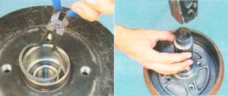
After this, unscrew the two nuts and one bolt of the shock absorber cup, this is done to make removal easier. First, I unscrewed two nuts, they were marked with pink and purple paint, then I unscrewed the bolt from below and pulled out the shock absorber drain.
Unscrew the upper mount (cup) of the shock absorber
All rubber bands, washers and spring gaskets on the shock absorbers are in good condition, there is no need to change them. So to replace the rear shock absorbers, you only need to purchase the shock absorbers themselves.
Removed old shock absorber (original KYB)
We disassemble the car's shock absorbers
Then, using spring ties taken from a neighbor in the garage (you will have to buy one for yourself, the ties are the simplest, I saw them in a UAZ store for 220 rubles), we compress the shock absorber spring, unscrew the upper rod nut completely and disassemble the shock absorber in parts.
Shock absorber spring compression
Disassembled old rear shock absorber
All components were cleaned and washed, the condition seemed to be slightly used. Only the springs could be tinted at the points of contact.
Assembly and installation of new shock absorbers
Now you need to assemble everything in the reverse order, since the old rubber bands are still there; the place for the spring has already been pressed in, so there is no need to remember the position, everything is assembled simply and quickly. We do not tighten the shock absorber rod nut too much; it is finally tightened when the car is already standing on both wheels. Therefore, shock absorbers are replaced at the same time, left and right.
New rear shock absorber KYB 341816 assembly
New suspension shock absorber ready for installation
We install the shock absorbers, tighten all the bolts except the top nut of the rod, with the tightening torques specified in the instructions, lower the car onto the wheels, tighten the nut of the rod. And as a result, we enjoy the performance of the new shock absorbers during the trip. ????
New installed Kayaba shock absorber 341816
Here is a video of the condition of the right shock absorber, the rod extends much longer than on the new shock absorber, on the left shock absorber there were no signs of life at all, the rod stood still.
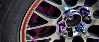
Selecting the right fasteners
The main thing when installing wheels on a car is to tighten the fasteners so as to prevent them from loosening while driving. This can lead to spontaneous removal of the wheel, and it is clear what the consequences will be. Although, a fairly experienced driver will already understand from the characteristic knock that the wheel fastening has become loose and will take action.
Sometimes self-loosening of the connection occurs due to incorrect selection of fasteners for the disks. This does not mean, of course, the thread - if the pitch is wrong, then you simply cannot screw in the nut or bolt. We are talking about the shape of the bolt head or the lower edge of the nut, which can be either conical or spherical. And the nut can also be blind, through, short, tall, or have a pressure washer.
If the fastener is chosen correctly, it even tightens itself during the ride. In addition to the function of holding the wheel on the hub, bolts and nuts also center the rim relative to the axis of rotation. What helps in this is the shape of the head or edge of the fastener, for which the disk has seats of the appropriate type. The cone is centered with the cone, the sphere with the sphere - a violation of such a tandem leads to loosening of the bolts or nuts after just a few kilometers of movement.
Tightening the wheel bolts
A few important nuances
In order to protect the car that sleeps under the entrance doors, many car owners put locks on the wheels. This is a set of four nuts or bolts (one per wheel) that cannot be unscrewed with a regular wrench.
- For this purpose, the kit contains a special key, the configuration of which corresponds to the individual shape of the hole on the nut or in the bolt head. The lockers do not need to be tightened as tightly as the main fasteners, so the tightening torque of the wheel bolts or nuts does not apply to them.
- It is very important not to use fasteners with broken threads or crumpled edges to secure wheels. If you see such a defect, replace the nut or bolt with a new one, similar not only in thread, but also in strength characteristics. And only factory production provides them.
- Today, alloy wheels are often produced in a universal version, so that they can be installed on different cars. In this case, the size of the hub hole (DIA) is made as large as possible, and they switch to a smaller size due to the installation of hub adapters.
- Without these liners, even if the difference is only a millimeter, the load on the fastener increases. Its holes become deformed and the wheel begins to rotate along the trajectory of an oval rather than a circle. The steering wheel begins to beat, and this is especially felt at speeds closer to 100 km/h.
Not understanding what is happening, the car owner turns to a tire shop. New balancing does not solve the problem, but meanwhile the shock absorbers and chassis elements on the car are destroyed, and the wheel studs break. The reason for this is the lack of small plastic rings costing 50-75 rubles.