07/18/2021 5,882 Security system
Author: Ivan Baranov
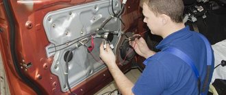
Many cars today are equipped with central locks, which increase the convenience and efficiency of vehicle protection. But not every car enthusiast knows the structure and operating principle of such a system. Where is the control unit located, is it possible to reliably protect your car with central locking, how to install the device - read about it further.
[Hide]
How the central lock works
The central locking algorithm consists of sending an impulse to the VAZ 2114 central locking control unit, which analyzes the received signal and generates commands that control the door locks. They are either opened or locked.
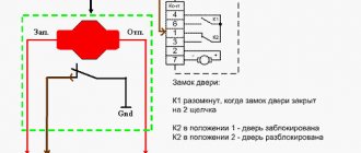
General scheme of central locking
Elements that activate the central locking are connected to pin 30. If contact 87 closes, then the activator outputs will be affected by ground. When a certain relay 30 is activated, the contact will connect to the positive. Thus, the activator will receive power and the rod will begin to move. The control unit rod closes different pairs of signals depending on what action needs to be performed: closing or opening the doors.
Since the central locking activators are connected in parallel, all doors will either open or lock at the same time. Central locking can be pneumatic or electric. The first type of device includes a control panel, compressor and tubes. In an electric one, the main element is a motor, thanks to which the mechanisms are activated.
Functions of remote controlled locks
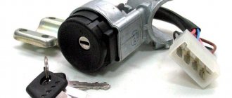
Types, design and principle of operation of the ignition system
Fierce competition forces manufacturers to continuously work to improve remote-controlled locking devices, using new technologies, materials and original ideas.
Many remote control locks are equipped with additional functions. There are locking devices with a siren, which sound a loud alarm when an unauthorized person attempts to enter the premises. Some products are equipped with a fire alarm sensor.
Most locks with remote control can be equipped with the required number of remote controls.
Modern self-powered electronic locks monitor the condition of the batteries. When the supply voltage level critically decreases, an alarm is triggered. To control the remote control device in an emergency, power is supplied through a special connector or another alternative opening option is provided.
Lockitron brand remote control locks use a smartphone or other Android or iOS device with WiFi, NFC or Bluetooth as a key. Each Lockitron lock has its own web page. This high-tech product is capable of receiving commands from any corner of the planet. It transmits information to the owner in the form of SMS about each opening or mechanical impact on the door or the lock itself - a knock, an attempt to break into or damage to the door.
If necessary, the device is programmed to automatically open when the owner appears in the Bluetooth or NFC network coverage area.
Possible malfunctions of the locking system
If there is no reaction when you turn the key in the lock or press a key on the remote control, this means that the central locking is not working.
All causes of central locking malfunction can be divided into two types:
- technical;
- related to climatic phenomena.
In the first case, breakdowns are possible due to incorrect installation or configuration of the locking system. Subject to natural wear and tear after long-term use. The service life directly depends on the quality of the device.
In the second case, the central locking system may fail under the influence of low temperatures and it may freeze. The lock may not work if water gets into the mechanism during rain or melting snow.
The central locking system may not work due to an incorrectly installed or faulty alarm system. In this case, you should diagnose the locking system. The control activator is installed in the driver's door. As soon as the drive is activated, signals are sent through the appropriate channels to the remaining activators, according to which the required action is performed. Therefore, you should check the operation of the lock using the key and the button on the key fob.
If the doors sometimes close, sometimes they don’t, then the reason may be in the control circuit or a violation of the integrity of the electrical circuit of the car alarm. The reason why the central locking system fails to operate may be insufficient battery charge or a blown fuse. Depending on the circuit being used, there may be multiple fuses. They all need to be checked and faulty ones replaced.
The fuse can burn out as soon as it is installed, due to a short circuit or overload, for example, when controlling the central locking with a key fob, and not manually. In warm weather, the reason is a short circuit, which is possible due to poor contacts or an open circuit. The cause of the breakdown may be a malfunction of the central locking control unit.
You can check the operation of the unit using a multimeter by checking the power supply to the activators. Current is supplied to the contacts of the unit by unlocking and locking the driver's door. If the control unit is broken, it needs to be replaced.
How to prevent central locking failure?
Experts recommend regularly carrying out diagnostic work to identify all faults at the initial stage. A small wire crease can be eliminated in just a few seconds, which will allow the electrical circuit to maintain its functionality longer. Having the driver's supply of fuses will make it possible to repair the system in a short time, due to which the delay on the road will be minimal. With proper care, a central lock lasts much longer than a complex alarm system, and the security properties of the system are sometimes much better.
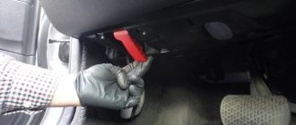
Repair features
If the central locking of the VAZ 2114 has stopped working, then you need to conduct diagnostics and find the cause of the breakdown (the author of the video is Nikolay Bogdanov).
Then carry out the appropriate repairs. Problems with central locking on the VAZ 2114 most often arise at low temperatures and high humidity. The reason is the locks with solenoids that are installed from the factory. It is better to replace them with locks with an electric motor.
If the drive is not working on only one door, it is necessary to check its electrical circuit for an open circuit by testing it. Most often, broken wires are located in the corrugation. Since the doors are opened and closed frequently, the insulation cannot withstand the load. The break is restored by replacing the wire and connecting the broken sections using female-male terminals.
If there is no break, the cause may be a failure of the control board or switching relay. The winding of the motor or solenoid may burn out, and the drive gears may wear out. In this case, the door auxiliary drive may need to be replaced.
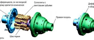
Central locking device
A central lock is a complex of units with an electromechanical drive.
The central lock includes the following components:
- Control block;
- input sensors and buttons;
- actuators (activators).
Central locking components
The trunk lid and fuel filler flap can also be equipped with locking devices connected to the central locking system.
Control block
The control unit monitors the position of limit switches, control buttons, as well as contact groups of door locks and other sensors that are connected to the unit by wires.
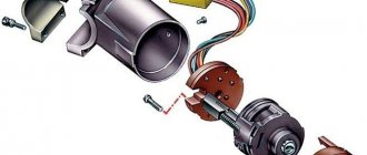
Initially, the electronic part of the unit was contained in one housing with connectors. However, new car models also use CAN buses, with which you can divide the central locking control system into separate elements. This allows you to install them in different places on the body.
Example of a central locking control unit
Additionally, the BU may include:
- Sending a signal to the turn signals, which flash briefly when locked/unlocked. With this option, the alarm can be connected to the appropriate wires and the turn lights will be activated.
- Receiver of signals from the remote control. If this receiving device is located outside the unit, then the connecting wires can also be used to control the car alarm.
If the central locking system has a multifunctional complex control unit, then most of the wires of the installed security system are connected to its connectors. A siren, alarm sensors, and, if available, an engine blocking device will require separate connections.
Input sensors and buttons
The central locking system includes several groups of input sensors used in alarm installation:
These include:
- “Limit switches” are limit sensors of car doors that determine their closed or open position. The supply of light to the corresponding lights in the cabin depends on their signals.
- Door lock microswitches. They signal the closed/open state of the car door lock.
- Microswitches in the electric lock drive. They send signals about the status of door locking devices - locked/unlocked.
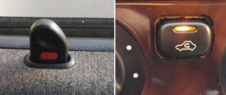
The control button in the cabin can be one on the driver's door or on the panel, or two on both front doors. The central locking is usually controlled using a two-way button with three contacts - one common and two normally open. There are also two- or five-pin keys.
Actuators
There are electromechanical drives and pneumatic drives for central locking actuators (activators).
Electric drive
There are several different types of electric drives with a traction force of 2.5 - 6 kg. The most common types are square and T-shaped (“pistol”).
The electric drive mechanism is housed in a plastic case. Structurally, it consists of an electric motor and a metal (or plastic) gearbox. When the polarity of the voltage supplied to the electric motor changes, the shaft rotates either clockwise or counterclockwise. Torque is transmitted to the gearbox, which converts rotational motion into linear motion. The direction of rotation determines whether the door lock is locked or unlocked.
The drives are controlled by short-term pulse voltage - lasting from 0.8 to 1.5 seconds. This is enough to trigger the lock mechanism to open or close. If the voltage supply time is made longer, the electric motors will fail.
Electric door lock circuit diagram
Among electric drives there are options with two electric motors. One is used to close/open the lock, the second blocks the mechanical drive of the locking device, preventing it from being opened from inside the car using a handle or rod. Such electric drives are controlled by three wires.
Electric motors differ in the presence or absence of a contact microswitch mechanically connected to the retractable rod. Two motor wires complemented by three switch cables form a five-wire electric drive.
They are usually installed in the front doors of the car, and a microswitch transmits signals to the two-wire motors found in the rear door locks. The corresponding commands (to close or open) are sent when the front doors are locked or unlocked with the key or when the control button is pressed.
Photo gallery: types of electric drives
Pneumatic drive
The main design element of the pneumatic actuator is a rubberized membrane with a rod, placed in a plastic housing, which contains a fitting for air supply. Under pressure, the membrane rises, and under vacuum it lowers, moving the rod and locking or unlocking the lock.
Some pneumatic devices, like electric drives, are equipped with a contact microswitch. It is connected mechanically to the rod and works on the same principle as in electromechanics.
Some types of pneumatic actuators have electromagnets with a movable core (solenoids). They serve as additional protection and prevent unauthorized attempts to open the lock. If an effort is made to lift the rod without an enabling command from the control unit, the microswitch is activated and voltage is applied to the solenoid. The electromagnet core blocks the rod, at the same time a command is sent to the compressor to create a locking vacuum of air.
Installation instructions for central locking
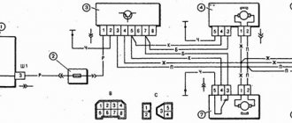
Before installing the central locking system, you should study the connection diagram
Photo gallery “Central locking diagrams”
The central locking control module is located on the left side under the panel. There are 6 wires coming from it. To install the central locking system, you need to disconnect the brown and blue wires.
Before connecting, you need to check that activators with 5 outputs are installed in the doors. If they are missing, they should be installed.
In a VAZ 2114 car, the wire responsible for opening the doors is usually white and connected to terminal 7. If there is no connection to terminals 7 - 5, then the 8th terminal is connected to the brown wire. This wire is responsible for opening the doors. Terminals 5 and 6 are for closing doors.
To install the central locking system, you must purchase additional items:
- 2-3 diodes 1N4001 at 1A;
- one diode 1N5401 3 A;
- 2 diodes of 4 or 5 A, if there are no separate outputs for turn signals.
After connecting the central locking system to the alarm, you need to check its functionality.
Schemes for connecting the alarm to the central locking system
The first of the possible options has already been considered: two wires are pulled from the central lock control unit to the signaling system, which are control wires.
Connection diagram of control unit central lock
In this case, it is better to exclude the contact switch shown in the diagram. Its role, as is easy to understand, will be played by the alarm (main unit). Where there are no separate taps, you can make T-shaped connections by connecting to the limit switch wires. This option is standard, but not the only one.
Standard option for connecting blocks
So, we have a lock control unit (CU Central Lock), as well as an alarm unit. The latter is equipped with a pair of relays, the taps of which are located on a separate connector. Where this connector is located, you need to find in the instructions (the wiring is also given there). The connection diagram will look like this:
Standard connection to central locking
The upper relay is activated to close the locks, the lower relay is activated to unlock the locks. During the period of contact closure, it is set to the following value: 0.7 s or 0.8 s.
Let us note two important points: a pair of relays is usually equipped with a unit of any modern alarm system. And by default everything is configured as it should. The central locking control unit, in turn, cannot but have control wires, and, as a rule, there will be two of them. Just in case, let's consider another option: there the limit switch is connected only to the signaling device.
When the decision is made by the alarm
Until now, we have used connection to the control wires coming from the limit switches to the control unit. Now they will need to be broken: the role of limit switches will now be performed by relays built into the signaling system, and we will connect one of the limit switch contacts directly to the signaling system.
Connection to control inputs
When the input labeled "IN1" is grounded, it means the following: the driver actuator is fully open. This is the logic that is usually used.
The work algorithm looks like this:
- We press the pawl on the driver's door, and input IN1 is immediately disconnected from ground;
- Seeing the lack of potential at the input, the signaling program activates the “close” option (the lower relay is activated for 0.8 s);
- As a result, the brown wire going to the central lock control unit experiences zero potential within 0.8 seconds, and automatic closure (locking) occurs.
A similar logic comes into play when the pawl is raised all the way up: the limit switch closes, and so on. Having implemented the indicated scheme, we will leave the central locking functionality in place, but will also add the ability to control the lock from the signaling system. This was also typical for the first option, but there were minor differences: two limit switches were used there, and the central control unit analyzed slightly more information. And here the analysis actions are assigned to the signaling.
Input IN1 is configured by software
All wires that need to be connected are low-current, and they carry 200-300 mA. Installing the cables will be simple: just create an electrical contact, and that’s it. But the power, that is, supply wiring, is not so easy to handle. Therefore, we saved the “difficult” option for last.
Connection to power terminals signaling
The actuator motor, which has built-in limit switches, can be connected to the alarm relay contacts. In this option, the electrical connection between the two blocks (control unit central locking and alarm) is completely absent:
Scheme 3, the most difficult
When carrying out installation, you may need to experiment with the polarity of the motor connection (points 1 and 2). The signal pushes the electric drive rod, and this leads to the switching of the limit switch contacts. And they, that is, the contacts, are always connected to the control unit, which provides indirect communication between the blocks.
In many cars there is no motor in the driver's actuator, but the central locking works as it should.
The circuit above uses similar logic. A positive property is the absence of galvanic connection. The negative is that you will need to connect power cords to the relay. It is better to entrust this work to an experienced auto electrician. There is no need to overestimate your strength.
Let's look at the last of the schemes again. There is a common contact between two different modules here, this is mass. Also, they are powered by one battery, and the second common conductor will be “+12 Volts”. But in the car, all the units are connected to these two cords. So, talking about the lack of electrical communication is quite legitimate. This option, if implemented at the proper level, will be the most reliable.