from the network) The gasoline engine was invented a long time ago, but is used in our time. People have always wanted an engine that was powerful and economical. Many different options have been come up with. But not all are used in the modern world. Here we will look at the gas supply to the engine. This gas is called differently: brown gas, Brown's gas, hydrogen, water gas. It is made on the basis of water. The main advantage of the Brown system is the improvement of the environment. Gasoline is saved due to its better combustion. Often only about 15% of the gasoline's energy is converted into mechanical energy in the internal combustion engine. If the engine is supplemented with Brown gas, this will lead to the fact that the fuel will burn better, and the available energy from gasoline will be converted into mechanical energy. And this does not violate the laws of thermodynamics. When the gas burns, it produces dry water vapor. It serves to clean the valve-piston group from carbon deposits and improve heat exchange between the valve and the seat. As a result, the engine resource increases. Due to the fact that fuel consumption is reduced, fuel injector mileage increases, service intervals increase, and oil contamination decreases. One liter of water becomes wider by 1866 liters of flammable gas. You can drive 30-40 hours on each liter.
To convert water into gas at home you need: a catalyst, distilled water, electricity, electrodes. There are many ways to make a car on water with your own hands. But we will focus on one, simpler design. To assemble a Brown generator, you need to take 5 ml plexiglass, 20 meters of stainless steel wire (grade 316), a vinyl tube with a diameter of 4 ml and six 700 ml cans. The catalyst can be NaOH or NaOH (be sure to use rubber gloves, since these substances are alkali).
You can use only one can, instead of six, but be sure to take into account the following rules: - it is necessary to obtain a strictly defined amount of gas. For example, you will need 0.7-1.5 liters of gas per minute, provided that you have a 1.5 liter engine; -the temperature of the electrolyte and the amount of gas strongly depend on the voltage on the electrodes. The electrolyte can heat up to 60 degrees in just two hours at 12V power. This will be a lot, so it is better to supply 6V rather than 12V. To do this, you need to turn on two jars one after the other. But then the amount of gas produced will drop. You need to take more cans - preferably six (all in parallel and two in series).
Then everything is very easy - you need to cut out the plates and connect them crosswise. Then wrap them with wire (2 electrodes) and secure them to the lid. It is necessary to make a fitting on the lid so that the gas comes out and special bolts so that the wires are attached to the electrodes. The electrodes should not be closed to each other, and the lid should be sealed when closing the jar. You need to pour approximately half a liter of distilled water into the jars, after adding half a teaspoon of NaOH. It turns out that 6 cans should consume a current of approximately 6V when connected correctly. This system should work on any car.
Read also: How to lubricate silent blocks when pressing in
Many car owners are looking for ways to save fuel. A hydrogen generator for a car will radically solve this issue. Feedback from those who have installed this device suggests a significant reduction in costs when operating vehicles. So the topic is quite interesting. Below we will talk about how to make a hydrogen generator on your own.
A car moving on water: what is it?
Many people have thought about the question - why can’t humanity change its attitude towards the technological component of life?
After all, minerals can be used in more thoughtful ways. We are not talking about common clean environmental technologies - wind power plants, the use of tidal energy or the heat of volcanoes. We are talking about revolutionary technologies for which the use of minerals is a thing of the past. For example, such a breakthrough could be an engine running on water. Humanity has been developing such technology since the advent of the internal combustion engine. Back in 1916, an enterprising comrade named Louis Enricht raised the question of an engine using liquid energy. According to Louis, he developed a secret “elixir” that converted liquid into fuel for the power unit.
During the demonstration of the miracle product, the inventor poured ordinary drinking water into the car’s gas tank and added the contents of the bottle to it. The public was extremely impressed by the results they saw. Even Henry Ford was amazed. He wanted to present one of his cars to Louis Enricht. But the unfortunate inventor turned out to be a charlatan, for which he was sent to prison, where he died.
From an engineering point of view, a water car is a vehicle that is driven by an engine that runs on clean water. These do not include:
- Steam power units.
- Cars where water is placed in the injection system to cool the cylinders. In such models, it not only cools the engine, but also reduces detonation and increases the compression ratio.
- Hydrogen vehicles. Despite the fact that hydrogen contains the necessary particles, electrolysis is required to extract them. During the reaction, water is split into oxygen and hydrogen atoms. The latter is fed into the fuel cell, where it burns. It turns out that the vehicle is powered by hydrogen.
- Power units with added water. This is the so-called Brown's gas. The technology was patented back in the mid-twentieth century and gained some popularity. Water also undergoes an electrolysis reaction, after which steam is supplied to the combustion chamber. As a result, efficiency increases, and the amount of harmful emissions into the atmosphere decreases.
But all this cannot be called an engine running on clean water.
Brown's Gas
Today, hydrogen backup power plants are becoming increasingly popular among motorists. However, this is not really what was discussed above. By electrolysis, water is converted into, in other words, Brown's gas, which is added to the fuel mixture. The main task that this gas solves is the absolute combustion of fuel. This serves to increase power and reduce fuel consumption by a decent percentage. Some mechanics have achieved savings of 40%.
The surface area of the electrodes is important in the quantitative gas yield. Under the influence of electric current, a water molecule begins to decompose into 2 hydrogen atoms and one oxygen. When burned, such a gas mixture releases almost 4 times more energy than when burning molecular hydrogen. Due to this, the use of this gas in internal combustion engines leads to more efficient combustion of the fuel mixture, reduces the amount of harmful emissions into the atmosphere, increases power and reduces the amount of fuel consumed.
Club of fans of minibuses and minivans
This is how the saturation of the gasoline-air mixture with water vapor in the throttle space of the carburetor is automatically regulated. To prevent steam from entering the cylinder with the intake stroke after stopping the engine 7, there are pneumatic shut-off valves 3 installed on the main and additional outlet pipes, opening at an excess pressure of 0.02-0.04 MPa, and an electrical delay circuit for closing the shut-off valve 18 after turning on the ignition switch and stopping the engine in the form of a serial chain of capacitor 15 and adjustable resistance 16, connected in parallel to the coil of the shut-off valve 18. To prevent the discharge of capacitor 15, a diode 17 is provided in the general circuit. The delay of valve 18 in the open position after stopping the engine allows excess the steam pressure contained in the pressure damper 11 forces water out of the steam generator into the water tank 21, and the subsequent closing of the shut-off valve 18 ensures that water stops moving through the inlet pipe towards the steam generator 8, because the internal diameter of the inlet pipe provides the capillarity effect. Condensation of the steam remaining in the steam generator, steam pressure damper, main and additional outlet pipes will occur on their walls and the walls of temperature sensor 10. Temperature sensor 10 during operation monitors the temperature of steam coming from steam generator 8, and if unevaporated steam enters the pressure damper there is water in the steam generator 8, the temperature sensor 10 will operate and, through its contacts 12, will close the power circuit of the electromagnetic relay 2, which will provide the shut-off valve 18, and the supply of water to the steam generator 8 will stop until the previously supplied water has completely evaporated. To ensure that the device does not operate in pulse mode, adjusting screw 19 is used to select such a water supply to the steam generator that ensures evaporation of all water entering the steam generator in maximum flow mode. The evaporator operating mode is monitored by control lamp 1. An additionally installed canister in the trunk or interior of the car can be used as a water reservoir. Considering that all components: pressure damper 11, main and additional outlet pipes 13 with electric heaters 14, shut-off valve 18 warm up after starting the engine, the device operates reliably even at subzero air temperatures. The need to descale the device is determined by reducing water consumption.
Current regulator
A hydrogen generator on a car increases its productivity during operation. This is due to the release of heat during the electrolysis reaction. The working fluid of the reactor experiences heating, and the process proceeds much more intensely. To control the progress of the reaction, a current regulator is used.
Read also: Hyundai xteer 5w30 synthetic oil reviews
If you do not lower it, the water may simply boil and the reactor will stop producing Brown gas. A special controller that regulates the operation of the reactor allows you to change productivity with increasing speed.
Carburetor models are equipped with a controller with a conventional switch for two operating modes: “Highway” and “City”.
Where does the water in fuel come from?
Some people mistakenly believe that the water in a car's fuel system comes from diluted fuel at a gas station. Sometimes gas station employees deliberately dilute the fuel liquid with water. However, in most cases, its appearance in fuel is a regular occurrence. Sudden temperature changes lead to its appearance. It is worth noting that temperature changes accompany fuel liquid both in storage tanks at gas stations and in the car tank. This is a continuous process, characteristic mostly of the winter season.
What could be the reason for this?
If the air temperature outside is lower than the temperature of the space unoccupied in the tank, then liquid in the form of condensation begins to form on its surface. This is where the water comes from.
Hydrogen engine design
Cars with a hydrogen engine are divided into several groups:
- Machines with 2 energy carriers. They have an economical engine that can run on pure hydrogen or a gasoline mixture. The efficiency of this type of engine reaches 90-95 percent. For comparison, a diesel engine has an efficiency coefficient of 50%, and a conventional internal combustion engine - 35%. Such vehicles comply with the Euro-4 standard.
- A vehicle with a built-in electric motor that powers a hydrogen cell on board the vehicle. Today it has been possible to create motors with an efficiency of 75% or more.
- Conventional vehicles running on pure hydrogen or a fuel-air mixture. The peculiarity of such engines is clean exhaust and an increase in efficiency by another 20%.
The main feature is the method of supplying fuel to the combustion chamber and igniting it.
As for the conversion of the received energy into the movement of the crankshaft, the process is similar.
Types of installations
At this time, a hydrogen generator for a car can be equipped with three electrolyzers of different types, nature of operation and productivity:
- Simple, cylindrical type. Creates 700 milliliters of gas per minute. This productivity is sufficient for engines with a displacement of up to 1.4 liters.
- With cells of separate type. It is the most effective in terms of design and productivity. The gas output exceeds 2 liters per minute. This volume makes it possible to use it in freight transport.
- Electrolyzer with open plates. This design provides additional cooling to the system, making it suitable for continuous operation of the unit. The gas output varies by the number of reactor plates.
The first type of design is quite sufficient for most carburetor engines. There is no need to install a complex electronic circuit for a gas productivity regulator, and the assembly of such an electrolyzer itself is not difficult.
For much more powerful machines, it is preferable to assemble a second type of reactor. And for diesel engines and heavy-duty vehicles, the Third type of reactor is used.
Modern cars with hydrogen engines
The possibility of using hydrogen fuel engines has attracted the interest of many manufacturers. As a result, more and more cars running on this gas are appearing in the automotive industry.
The most popular models include:
- Toyota has released the Fuel Cell Sedan. To eliminate problems with limited space in the cabin and luggage compartment, containers with hydrogen fuel are placed on the floor of the vehicle. The Fuel Cell Sedan is designed to transport people, and its cost is 67.5 thousand dollars.
- The BMW concern presented its version of the Hydrogen car. The new model was tested by famous cultural figures, businessmen, politicians and other popular personalities. Tests have shown that switching to a new fuel does not affect the comfort, safety and dynamics of the vehicle. If necessary, fuel types can be switched from one to another. Hydrogen7 speed is up to 229 km/h.
- Honda Clarity is a car from the Honda concern that impresses with its power reserve. It is 589 km, which is something no other low-emission vehicle can boast of. Refueling takes three to five minutes.
- General Motors' "Monster" premieres in October 2021. The peculiarity of the car is its incredible reliability, which is confirmed by studies carried out by the US Army. During testing, the vehicle traveled more than 3 million kilometers.
- Toyota has launched the Mirai hydrogen model on the market. Sales began in 2014 in Japan, and in the United States in October 2015. The Mirai takes five minutes to refuel and has a range of 502 km per fill. PHOTO 21 22 Recently, representatives of the concern announced that they plan to introduce this technology not only into passenger vehicles, but also into forklifts and even trucks. The 18-wheeler truck is already being tested in Los Angeles.
- Manufacturer Lexus is planning its hydrogen-powered version of the car in 2021, so few details are known about the vehicle.
- Audi presented the H-tron Quattro concept in Detroit. According to the manufacturer, the car can travel about 600 km on one tank, and it can reach speeds of up to 100 km/h in 7.1 seconds. The car has a “virtual” cockpit that replaces the standard dashboard.
- BMW, in collaboration with Toyota, plans to release its hydrogen vehicle by 2021. The manufacturer assures that the power reserve of the new model is more than 480 km, and refueling will take up to 5 minutes.
- In 2013, Ford announced that active production of hydrogen engines would begin by the end of 2021 in collaboration with Nissan and Mercedes-Benz. But it has not yet been possible to implement the plan in practice - the concern’s employees are at the development stage.
- Mercedes-Benz presented the GLC SUV at the Frankfurt Motor Show, which will appear on the market at the end of 2021. The car is equipped with a 9.3 kWh battery, and the range is 436 km. Top speed is electronically limited to 159 km/h.
- Nikola Motor presented a hydrogen-powered truck with a range of 1,287 to 1,931 km. The cost of a new car will be 5-7 thousand dollars per month for rent. Production is planned to begin in 2021.
- The Hyundai manufacturer has created a new Tucson line. To date, 140 vehicles have been produced and sold. The Hyundai Genesis brand presented its GV hydrogen-powered car. The vehicle was first presented in New York, but its production is not yet planned.
- The UK is also not lagging behind in terms of new technologies. The Riversimple Rasa hydrogen car can already be rented in the country for three or six months. The car weighs just over 500 kg and can travel about 500 km on one fill.
- The design house Pininfarina has created the H2 Speed hydrogen fuel car. The peculiarity of the car is its ability to accelerate to hundreds in just 3.4 seconds, and the maximum speed is 300 km/h. Refilling time is only three minutes. The cost of the new model reaches 2.5 million dollars.
How a car works on water (true or false).
When you come across screaming headlines that another inventor has invented a car that runs on water, you are certainly surprised
Well, how can water be fuel? Actually, there’s no way, but journalists, as always, are cunning to attract attention. In fact, all projects of engines on water have a distant relation to water
Of course, water is a compound of hydrogen and oxygen. And yes, hydrogen can be a fuel. But in order to break interatomic bonds and extract hydrogen from water, you need to spend a lot of energy; such electrolysis also occurs with the release of heat. And the second law of thermodynamics states that heat cannot be transferred from a colder to a hotter one. In general, this scheme is more than ineffective.
So what's behind the water cars? The fact is that not water, but aqueous solutions of salts are used as fuel. To simplify a little, the engine runs on salt water. What is salt water? This is an electrolyte, just like in regular batteries. And it is easier to extract energy from an electrolyte than from water.
In fact, a salt water engine, also called a “flux battery,” works on the same principle as a fuel cell using hydrogen (there are also fuel cells using methanol, alkalis or acids).
A simplified model looks like this. The brine solution flows through the membrane, where the solution undergoes an oxidation reaction, producing negatively charged electrons and positively charged ones, thereby creating an electric current. That is, we have a battery in which the brine solution is not closed inside the shell and thus, you can fill the tank with as much fuel as the tank itself allows. As with other types of fuel cells, this one uses two types of fluid, meaning you have to fill 2 separate tanks.
One solution is needed for the oxidation reaction, the other for the reduction reaction. Thus, the entire system is more like a battery, since it can be recharged; well, at worst, the liquid in the tanks can be filled with completely new one.
The most interesting thing is that the history of fuel cells itself is not new. The principle was discovered back in the 19th century, and the first working fuel cells appeared in the 50-60s of the twentieth. Many of them were even used to power equipment on spacecraft.
The efficiency of fuel cells and engines based on them is higher than that of internal combustion engines, because the conversion of chemical energy into electrical energy occurs without combustion of fuel, and there are very few moving parts (in which friction energy is consumed) in such a system.
Unlike hydrogen fuel cells, the version of the machine using brine solutions looks more promising, since the chemical industry and infrastructure are more ready for the production of brine solutions than for the production of hydrogen.
When will we start driving cars on salt water, you ask? They're already on their way. The Liechtenstein-based nanoFlowcell claims that it has already certified its Quant e-Sportlimousine, Quantino and Quant F cars for the EU countries. The dynamics of the e-Sportlimousine are impressive (for those who are accustomed to gasoline engines), in 2.8 seconds the electric car can accelerate to 100 km/h at a maximum speed of 350 km/h, and its engine is capable of developing a power of 680 kilowatts (which corresponds to 920 hp). s.) and torque 2900 Nm. At the same time, the power reserve is promised to be 600 kilometers on one charge.
Quantino, a model intended for “mere mortals”, has more modest characteristics - 143 horsepower, but the power reserve is increased to 1000 km. Most likely, the modest Quantino will become the first production “car on water”. There is no reliable information yet about when such machines will appear on the market. But apparently we don't have to wait long. But if you don’t intend to wait at all, then on the Internet you can buy a toy car that runs on a solution of regular table salt for just a couple of dollars. So to speak, for “getting to know the technology.”
Source
My own hydrogen generator for a car
Would you like to save this interesting video?
- Complain
Complain about a video?
Liked?
Didn't you like it?
HHO standby power plants use electricity from the car's battery to generate hydrogen from water and are activated solely by driving. Hydrogen never accumulates: the resulting gas is immediately supplied to the engine, where it is mixed with the available fuel. https://www.freebie-here.rf/
The mixture of fuel and HHO burns much more efficiently, reducing fuel consumption and the amount of hazardous substances released into the air.
Savings are achieved through the most complete combustion of fuel, because simple combustion of fuel in internal combustion engines occurs inefficiently at only 30%-50%, the other 50-70% goes down the drain in the literal sense of the word. The M-Eco hydrogen engine system can safely save 20%, 30% or more of fuel, and depending on weather conditions, driving style, speed and other factors, savings reach 65%. Also, for gasoline engines, it is possible to safely switch from AI-98 gasoline or
AI-95 to AI-92, AI-80, and this is also saving
7-15% per 1 liter. Many passenger car models can safely drive using AI-80 simultaneously with the M-Eco system for cars on water as alternative fuels
Due to the fact that gas in the form of HHO (hydrogen and oxygen atoms, alternative fuels) when ignited, produces 5 times more energy than simple fuel in engines, it is possible to obtain an efficiency from engines from 7% to 40% more due to good combustion fuel, just add H2O.https://www.freebie-here.rf
The engine continues to run smoother, vibration levels are reduced, and it becomes more responsive at low speeds and low revs. In ordinary words, the old car becomes noticeably younger and more energetic. What is important in city driving conditions, and also when transporting cargo.
Injecting water into a car engine
Whenever the outside air temperature changes from above zero to above zero, condensation in the fuel tank is actively formed. This causes the formation of large volumes of water in it. The formation of this type of liquid in the fuel system can also be caused by different engine operating modes. As a result, it may happen that from twenty to eighty percent of the fuel liquid can return back to the tank after injection. This will cause the temperature between the environment and the tank to differ even more, which means that even more water will be formed.
It is worth concluding that the appearance of water in the fuel system does not always depend on the person. Much more often this is due to nature.
Why is it necessary to purify fuel from water?
This question may not puzzle many people. The answer is known to a large number of people. The fuel pressure in the place where the pairs of plungers are located is two hundred atmospheres. The water present in the fuel fluid can cause rust to form on metal parts.
The injector nozzles begin to become unusable, and the engine begins to consume a large amount of fuel. Most people know that water in fuel fluid can cause a lot of problems. Unfortunately, not everyone knows how much money will have to be spent on repairing the fuel system.
On new engine models, fuel is injected into the combustion system using pump injectors. For example, repairing six injectors of this type for owners of Volvo FH12 engines will cost approximately four thousand euros. To this should be added the costs due to vehicle downtime. This makes you wonder why it is necessary to purify fuel from water. The simplest solution to getting rid of small amounts of water in fuel is to install a separator.
Water in carburetor
What to do if water gets into the carburetor. The car immediately begins to twitch, and sometimes even stalls. Often simply opening the carburetor, drying and blowing the jets does not help. Let's find out what to do in such cases.
How does water get into the carburetor? It turns out there are several reasons.
water engine
A water engine relates to energy; it allows you to convert the potential energy of water, when working bodies filled with it fall, into mechanical energy, which directly or through its subsequent conversion into electrical energy can be used in various sectors of the national economy. The objective of the proposed utility model is to increase the energy efficiency of the engine in different mining and hydrogeological conditions, in wells by more fully using the gravitational energy potential with a large difference in the depths of the aquifer and the permeable absorption interval. Figure 1, as an example, schematically shows the device and principle of operation of the proposed water engine. Figure 2 shows a simplified kinematic diagram of the converter of alternating reverse rotation of the input shafts (reciprocating motion of the pistons) into rotational motion of the output shaft. The advantage of the proposed water engine is the higher energy efficiency of its operation in wider mining and hydrogeological conditions, incl. lower specific water consumption, higher developed power in different hydrogeological and technical conditions, all other things being equal. The use of the proposed water engine makes it possible to expand the range of non-traditional renewable energy sources (NRES) - means of “small” energy that use non-traditional, incl. renewable resources - groundwater in the natural conditions of their existence, as well as water from surface reservoirs. Subject to the condition that water consumption during engine operation does not exceed natural replenishment, depletion of groundwater reserves in a given
does not occur in the aquifer, its hydrostatic pressure is maintained, and the engine can operate indefinitely. Also, the advantage of the engine when powered from an aquifer and used as a source of electricity in comparison with river mini-hydroelectric power plants is the possibility of its trouble-free operation year-round in areas with a sharply continental climate, in particular, at low temperatures at which rivers freeze, since the used it contains the working fluid - underground water does not freeze.
The utility model relates to gravitational engines, the operating principle of which involves the conversion of the potential energy of a working medium, such as water, when it falls or working bodies filled with it into mechanical energy, and can be used in various sectors of the national economy.
The device will expand the range of non-traditional renewable energy sources (NRES) - small-scale energy resources that use non-traditional, primarily renewable resources - natural and artificial reservoirs, incl. groundwater, as well as rivers with small watercourses.
A percussion-rope drilling device is known (Shamshev F.A. et al. Technology and equipment of exploration drilling. Third edition, M., Nedra, 1983, pp. 464-469 [1]), including an engine, a reversible winch drive with a rope to which a percussion projectile with a tool located in the well is attached. In the device, the impact projectile with the tool periodically rises in the well above the bottom to a certain height and is subsequently dropped, the latter falling under the influence of its weight. Potential energy turns into kinetic energy and when the tool hits the bottom of the well, work is done. To operate the device, energy is supplied from outside. The device does not allow continuous generation of energy.
The closest technical solution chosen as a prototype is a water engine according to the RF invention patent No. 2224134 “Water engine”. M. class F 03 C 1/02, publ. Bulletin No. 5 02/20/2004 [2].
The water engine includes a feed tank, a crankshaft with a flywheel and main bearing supports, connecting rods, a piston, working chambers, and cylinder liners located below the crankshaft. There is a gap without sealing between the piston and cylinder liner. Water
the engine is equipped with intake and exhaust valves, a distributor device interacting with the intake and exhaust valves, and a guide rod with a guide bushing. The piston is equipped with a bracket, is made hollow and is equipped with overflow valves that operate in its lower and upper positions. The parts located below the crankshaft are installed in a mine working, for example a borehole, intersecting a permeable absorption interval with two coaxial casing strings of a larger and smaller diameter installed in it. The feed tank is formed by an annular volume between the casing columns and connected to a renewable source of water, for example, an underground aquifer. Such sources can be surface waters of natural and artificial origin - a river, lake, reservoir, storage tanks for waste and industrial waters, etc. The working chamber is formed by the volume of a casing string of smaller diameter, in which an inlet valve is installed, an outlet valve is installed in a well below the working chamber . Below the casing there is a permeable absorption interval intersected by the well.
The disadvantage of the known engine is that when it is “powered” from an underground aquifer, the efficiency of its use is limited by certain mountain and hydrogeological conditions. Moreover, with a deep position of the aquifer and its static and dynamic levels, the inefficiency of the engine is explained by the large geometric dimensions of the rod, the length of which should reach tens of meters, and, as a consequence, the elements of the crank mechanism. Large geometric dimensions are associated with the resulting forces of resistance to its movement due to the characteristic large friction forces and moment of inertia. These forces reduce the forces initiating the movement of the piston during engine operation, and, as a result, reduce (worse) energy efficiency, for example, developed
power under otherwise identical conditions. In practice, the implementation of such dimensions of a crank mechanism is technically and economically infeasible.
In addition, the disadvantage of the known engine is that with a large difference in the depths of the aquifer and the permeable absorption interval, the gravitational potential of the “feeding” (aquifer) water determined by it is not used in full.
The difference in the depths of the aquifer zone and the permeable absorption interval can be tens or more meters.
Theoretically, it is advisable to use the gravitational component of the working stroke (due to gravity) over the entire interval from the aquifer zone to the permeable absorption interval. The potential energy of a piston filled with water can be determined from the expression:
Wп=mgh, where
Wп—potential energy of the piston, J;
m—piston mass, kg;
g—gravitational acceleration, m/s2;
h is the height of the piston drop (the difference between the positions of the depths of the aquifer zone and the permeable absorption horizon), m.
In this case, the engine stroke can be up to several tens of meters or more. Taking into account the provisions of the theory of mechanisms and machines, as well as the above arguments about increasing resistance forces opposing the forces initiating movement, the use of a crank converter with large piston strokes is, in practice, both technically and economically inexpedient and difficult to implement. This explains the impossibility of realizing the gravitational energy potential of “feeding” water under the specified well conditions using a known engine.
The objective of the proposed utility model is to increase the energy efficiency of the engine in different mining and hydrogeological conditions, in wells by more fully using the gravitational energy potential with a large difference in the depths of the aquifer and the permeable absorption interval.
The task is achieved as follows. A water engine containing a feed tank, a converter of reciprocating motion of the piston into rotational motion of the output shaft with a flywheel mounted on it, a first working group including a hollow piston with an exhaust valve operating in its lower position, a working chamber-cylinder liner located below the converter translational movement of the piston into rotational movement of the output shaft. In this case, between the piston and the cylinder liner there is a gap without a seal, as well as a valve with a device that controls it, for example a cam mounted on the piston, inlet and outlet channels, and the parts located below the converter of the translational motion of the piston into the rotational motion of the output shaft are installed in the mine workings , for example, a borehole intersecting a permeable absorption interval with two coaxial casing strings of larger and smaller diameter installed in it. The feed tank is formed by an annular volume between the casing strings and connected to a water source, for example, an underground aquifer, and the working chamber is formed by a casing volume of a smaller diameter. In this case, the permeable absorption interval intersected by the well is located below the casing string of smaller diameter. Additionally, the engine is equipped with a second working group similar to the first. The supply channels are made to ensure that the feed container communicates with the cavity of the pistons and that they are filled with water by gravity in their upper position, and the pistons are connected to each other by a rope covering two pulleys installed
by means of one-way clutches, such as overrunning clutches, on the input shafts of a converter, such as a gearbox or multiplier, alternating reverse rotation of the input shafts into one-way rotation of the output shaft.
Figure 1, as an example, schematically shows the device and principle of operation of the proposed water engine. Figure 2 shows a simplified kinematic diagram of a converter for alternating reverse rotation of the input shafts (reciprocating motion of the pistons) into rotational movement of the output shaft, and subsequently the converter.
The downhole water engine contains: 1, 1′ - feed tank; 2 - aquiferous underground zone; 3, 3′ - inlet valves of the first and second working groups, respectively (in the following, the designation with a prime means the element of the same name belonging to the second working group); 4, 4′ — sleeves; 5, 5′ — pistons; 6 - rope; 7, 7′ — pulleys; 8, 8′ - single-acting couplings; 9 - converter for alternating reverse rotation of the input shafts into rotational movement of the output shaft, and subsequently - the converter; 10, 10′ — intake cams; 11, 11′ — piston exhaust valves; 12, 12′ — piston exhaust valve stops; 13, 13′ — output channels; 14 - permeable absorption interval; 15, 15′ - intermediate gears of the first and second working groups, respectively; 16, 16′ — single-acting output couplings of the reversible gearbox (multiplier); 17 — output gear with output shaft; 18 — flywheel; 19 — output shaft; 20 — air cap; 21 - fitting; 22 - intermediate roller pulley.
The water engine works as follows. Feed tanks 1 and 1′ are filled with water from the underground aquifer zone 2 through filters installed in a casing pipe of larger diameter. One of the engine pistons, for example, piston 5, is brought to its top dead center (TDC) - the position is shown in Fig. 1 (piston connection
carried out using an auxiliary device, incl. manual, which is not shown in Fig. 1). In this case, the piston 5′ connected to it is installed at its bottom dead center (BDC). In this state of the engine, the piston 5 with the cam 10 installed on it opens the inlet valve 3 and water from the feed tank 1 enters the cavity of the piston 5, and the outlet valve 11′ of the piston 5′ interacts with the stop 12′, opens and water from the piston 5′ flows into well 13′ and further into the permeable absorption interval 14. The cavity of the piston 5 is filled with water, and the cavity of the piston 5′ is freed from water, while the weight P1 of the piston 5 increases, and the weight P2 of the piston 5′ decreases. After completion of the filling-outflow processes, due to the excess of P1>P 2, the piston 5 begins to move downward, while the piston 5′ moves upward. When the piston 5 moves down and the piston 5′ moves up, the movement of the rope 6 causes the pulleys 7 and 7′ to rotate in a counterclockwise direction. Pulleys 7 and 7′ are connected to the shafts by means of one-way clutches, for example overrunning clutches, installed so that when the rope moves in each direction, one of the overrunning clutches is activated. When the piston 5 moves downwards, rotation is transmitted from the pulley 7 through the overrunning clutch 8 to the input shaft of the block 7. Rotation of the input shaft of the pulley 7 through gears 15 and 17 (Fig. 2) installed in the converter of alternating reversible rotation of the input shafts into the rotational movement of the output shaft 9 , is transmitted to its output shaft 19 on which the flywheel 18 is installed. When the piston 5 reaches its BDC, its exhaust valve 11 interacts with the stop 12 installed in the well and opens, and the piston 5′ reaches its TDC, while the cam 10′ installed on it opens inlet valve 3′. With this position of the pistons, water flows out from the cavity of the piston 5, and the cavity of the piston 5′ is filled with water. After completion of the filling-outflow processes, due to the excess weight P2>P1, the piston 5′ begins to move downward, while the piston 5 connected to it by the rope 6 begins to move upward. When the piston moves
5′ down, and the piston 5 up, the movement of the rope causes the pulleys 7 and 7′ to rotate in a clockwise direction. With this direction of movement of the rope, the rotation of the pulley 7′ is transmitted through the overrunning clutch 8′ to the input shaft of the pulley 7′. The rotation of the input shaft of the pulley 7′ is transmitted through gears 15′ and 17 to the output shaft 19. Subsequently, the engine operating cycle is repeated.
Thus, in a system of two pistons connected to each other by a rope, under the influence of gravitational forces of pistons alternately filled with water, their periodic downward and upward movements are established. The power developed in such a dynamic system is initially determined by the force in the rope and the linear speed of its movement, and on the output shaft - taking into account the reversible transmission system of the gear (multiplier) type.
In the gearbox (multiplier) of the converter 9, single-acting output couplings 16 and 16′ are additionally installed. The use of these couplings in the engine makes it possible to eliminate idle rotation of gear 15 when transmitting rotation from pulley 7′ to output gear 17, as well as to eliminate idle rotation of the input shaft of pulley 7′ when transmitting rotation from pulley 7 through gears 15 to output gear 17.
The engine is stopped using compressed air, for example, accumulated in a cylinder (not shown in figure 1). A hose connects the cylinder with a valve to fitting 21. To stop the engine, the cylinder is connected to fitting 21 and compressed air enters the annular volume above the liquid level - air cap 20. As the pressure in the air cap increases, the level in the liquid in the annular volume begins to move down, and the volume of the air cap increases. When the liquid level is positioned below the inlet valve 3′, the possibility of water entering from the annular volume and 1′ into
the piston cavity is 5′ when it next reaches TDC. Engine operation stops.
In the proposed engine, the working stroke of the piston 5 (5′) from TDC to BDC is the distance (S svd) from the water-bearing zone to the permeable absorption interval, which can be tens or more meters and is many times greater than the working stroke of the piston (Svd) of the crank mechanism of the water engine according to the prototype. With equal volumes of the piston cavities, the work performed by an equal volume of water during the working stroke of the piston (Asvd) in the proposed engine Asvd=RG*S cvd can many times exceed the work (A vd) performed during the working stroke of the piston in the prototype A vd=RG*Svd, that is Asvd>Avd, because Ssvd>Svd . The following notations are used in the formulas:
RG - gravitational force, determined by the gravity of a piston filled with water in the air, kg*m/s2 (for the purpose of simplicity, the resistance forces to the movement of the pistons, which are also active in the prototype, are omitted);
RG=m*g, where
m is the mass of the piston with water, kg;
g—gravitational acceleration, m/s2.
The gravitational potential determined by the difference in the depths of the aquifer and the absorbing permeable interval in the proposed water engine is fully realized.
At the same time, the specific water consumption, which is its consumption per unit of work and is an indicator of energy efficiency (energy efficiency) [3], for the proposed water engine is significantly lower (better) than that of the prototype, in conditions of a large difference in the depths of the aquifer zone and the permeable absorbing horizon.
The design and operating principle of the proposed water engine eliminates the unevenness of each of the alternating initiating
forces acting on the piston. This is explained by the identity of the conditions for their formation.
Other options for feeding a borehole water engine with water are also possible, for example, when the feeding tank is represented by reservoirs of natural or artificial origin located above the wellhead, incl. technical hydraulic systems.
The advantage of the technical solution we propose in comparison with the water engine adopted as a prototype is the higher energy efficiency of its operation in wider mining and hydrogeological conditions, incl. lower specific water consumption (water consumption per unit of work), greater developed power in different hydrogeological and technical conditions, all other conditions being equal to the prototype.
The engine can be used to provide energy supply as a converting power element in a source of electrical energy when connecting its output shaft (with a flywheel) to an electric generator.
The use of the proposed water engine makes it possible to expand the range of non-renewable energy sources - means of “small” energy, using non-traditional, incl. renewable resources - groundwater in the natural conditions of its existence. If the condition is met that the water consumption during engine operation does not exceed natural replenishment, the depletion of groundwater reserves in a given aquifer does not occur, its hydrostatic pressure is maintained, and the engine can operate indefinitely. Also, the advantage of the engine when powered from an aquifer and used as a source of electricity in comparison with river mini-hydroelectric power plants is the ability to operate it year-round in areas with a sharply continental climate, in particular, at low temperatures at which rivers
freeze because the working fluid used in it - underground water - does not freeze.
With other options for powering the engine with water from its sources of natural origin located above the surface of the day (river, lake, etc.), the use of the engine allows the implementation of a renewable, non-traditional source of electricity. When powering the engine from sources of artificial origin (technical hydraulic systems), incl. wastewater, the use of a motor can realize their gravitational potential by generating electricity. At the same time, water that has fulfilled its functions in technical hydraulic systems is a secondary energy resource.
When using the proposed engine as an energy source, an energy-saving effect is achieved in comparison with the use of traditional energy sources and energy supply schemes.
Sources of information taken into account
1. Shamshev F.A. and others. Technology and equipment of exploration drilling. Ed. 3rd, M., Nedra, 1983, pp. 464-469).
2. RF Patent No. 2224134 “Water Engine”. M. class F 03 C 1/02, F 03 B 29/08, F 03 B 17/00, publ. Bulletin No. 5 02/20/2004 - prototype.
3. GOST R 51541-99. Energy saving. Energy efficiency. Composition of indicators. General provisions. M., Standards Publishing House, 1998
A water engine containing a feed tank, a converter of reciprocating motion of the piston into rotational motion of the output shaft with a flywheel mounted on it, a first working group including a hollow piston with an exhaust valve operating in its lower position, a working chamber-cylinder liner located below the converter movement of the piston into the rotational movement of the output shaft, while there is a gap without a seal between the piston and the cylinder liner, as well as a valve with a device that controls it, for example, a cam mounted on the piston, inlet and outlet channels, with parts located below the reciprocating converter the movement of the piston into the rotational movement of the output shaft, installed in a mine working, for example, a borehole crossing a permeable absorption interval with two coaxial columns of casing pipes of larger and smaller diameter installed in it, while the feed tank is formed by an annular volume between the casing columns and communicating with a water source, for example, with an underground aquifer, and the working chamber is formed by the volume of a casing string of smaller diameter, and the permeable absorption interval intersected by the well is located below the casing strings, characterized in that it is equipped with a second working group similar to the first, the supply channels are made to ensure communication conditions a feeding tank with a cavity of the pistons and filling them with water by gravity in the upper position of the pistons, and the pistons are connected to each other by a rope covering two blocks installed by means of one-way clutches, for example, overrunning couplings on the input shafts of the converter of reciprocating movement of the pistons into the rotational movement of the output shaft, which is a two-input reversible gearbox or multiplier.
Hydrogen engine: types, device, principle of operation
TYPES OF HYDROGEN ENGINES
The first type of hydrogen engine runs on fuel cells. Unfortunately, hydrogen engines of this type are still very expensive. The fact is that the design contains expensive materials like platinum.
The second type includes hydrogen internal combustion engines. The operating principle of such devices is very similar to propane models. That is why they are often reconfigured to run on hydrogen. Unfortunately, the efficiency of such devices is an order of magnitude lower than those operating on fuel cells.
DEVICE AND PRINCIPLE OF OPERATION
The main difference between hydrogen engines and the gasoline or diesel analogues we are now familiar with is the method of supplying and igniting the working mixture. The principle of converting the reciprocating movements of the crankshaft into useful work remains unchanged. Due to the fact that fuel based on petroleum products burns slowly, the combustion chamber is filled with the fuel-air mixture a little before the moment the piston rises to its highest position (TDC). The lightning-fast reaction speed of hydrogen makes it possible to shift the injection time to the moment when the piston begins its return movement to BDC. In this case, the pressure in the fuel system does not have to be high (4 atm is enough).
Under ideal conditions, a hydrogen engine can have a closed-type power supply system. The mixture formation process occurs without the participation of atmospheric air. After the compression stroke, water remains in the combustion chamber in the form of steam, which, passing through the radiator, condenses and turns back into H2O. This type of equipment is possible if an electrolyzer is installed on the car, which will separate hydrogen from the resulting water for repeated reaction with oxygen.
In practice, this type of system is still difficult to implement. To ensure proper operation and reduce friction, engines use oil, the evaporation of which is part of the exhaust gases. At the present stage of technology development, stable operation and trouble-free starting of an engine running on detonating gas without the use of atmospheric air is not feasible.
Hydrogen fuel cell engine
Please note that hydrogen engines mean both units that run on hydrogen (hydrogen internal combustion engines) and engines that use hydrogen fuel cells. We have already discussed the first type above, now let's focus on the second option
A hydrogen fuel cell is essentially a “battery.” In other words, it is a hydrogen battery with a high efficiency of about 50%. The device is based on physical and chemical processes; in the body of such a fuel cell there is a special membrane that conducts protons. This membrane separates two chambers, one of which contains the anode and the other the cathode.
Hydrogen enters the chamber where the anode is located, and oxygen enters the chamber with the cathode. The electrodes are additionally coated with expensive rare earth metals (often platinum). This allows it to play the role of a catalyst that affects hydrogen molecules. As a result, hydrogen loses electrons. At the same time, protons pass through the membrane to the cathode, and the catalyst also affects them. As a result, protons combine with electrons that come from outside.
This reaction forms water, while electrons from the chamber with the anode enter the electrical circuit. The said circuit is connected to the motor. In simple words, electricity is generated, which makes the engine run from such a hydrogen fuel cell.
Such hydrogen engines allow you to travel at least 200 km. on one charge.
Marine internal combustion engines (SICE)
Diesel engine is a piston internal combustion engine operating on the principle of self-ignition of atomized fuel
IA Neftegaz.RU.
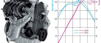
The first marine internal combustion engines (ICEs) appeared at the beginning of the 20th century. The Danish ship Zealand, built in 1912, had a diesel installation with 2 diesel engines with a power of 147.2 kW each.
Currently, the bulk of the main power plants installed on ships are internal combustion engines.
Only ships with engine power from 14,700 to 22,100 kW have steam turbine installations.
A diesel power plant consists of one or more main engines, as well as the mechanisms that serve them.
Depending on the method of implementing the working cycle, internal combustion engines are divided into 4-stroke and 2-stroke.
An additional increase in power is achieved through supercharging.
According to rotation speed, internal combustion engines are divided into:
In the 60s, simultaneously with the advent of adjustable pitch propellers, non-reversible internal combustion engines began to be used as the main engine, first on small ships, trawlers and tugs, and then on large merchant ships. Due to this, the design of the engines has been simplified.
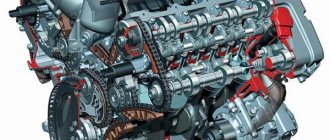
Engine room (diesel with auxiliary mechanisms).
A ship's power plant with an internal combustion engine is shown in the figure.
In addition to the main engine, there are 2 more auxiliary ones that drive the generators.
To service the main and auxiliary engines, auxiliary mechanisms and systems are used, as well as a system of piping and valves.
The fuel system is designed to supply fuel from tanks to the engine.
At the same time, to reduce viscosity, the fuel is heated and freed from liquid and solid impurities in separators and filters.
The lubrication system serves to pump lubricating oil through the engine in order to reduce friction between rubbing surfaces, as well as to remove part of the heat received from the engine and clean the oil.
The cooling system is designed to remove heat from the engine, which penetrates mainly through the cylinder walls and occurs during fuel combustion, as well as to cool the circulating lubricating oil.
This system consists of fresh and sea water pumps and water and oil coolers.
The launcher, which includes compressors, compressed air tanks, as well as pipelines and valves, is used to start the main and auxiliary engines.
Along with the above-mentioned auxiliary systems of the main and auxiliary engines, the engine room also contains other general-purpose ship machinery.
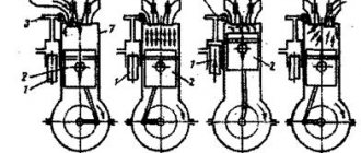
The operating principle of a 4-stroke internal combustion engine is shown in the figure below.
In a 4-stroke engine, the working cycle is carried out in 2 turns of the crankshaft, i.e. in 4 strokes of the piston.
Mechanical work is performed only during the 1st cycle, the other 3 are used for preparation.
During the 1st stroke, the piston moves towards the crankshaft.
Under the influence of the resulting vacuum, air rushes into the cylinder through the open suction valve.
In a naturally aspirated diesel engine, the intake air pressure is equal to atmospheric pressure; in a supercharged diesel engine, pre-compressed air is supplied to the cylinder. During the 2nd stroke, with the suction valves closed, the pre-entered air in front of the piston is compressed, resulting in an increase in temperature and pressure.
The fuel priming pump, the drive of which is coordinated with the movement of the corresponding piston, increases the fuel pressure.
When the pressure reaches 19.62-39.24 MPa, the fuel is injected through a nozzle into the cylinder, in which for naturally aspirated diesel engines the compressed air pressure is 2.94-3.43 MPa and the temperature is 550-600 ° C, and for supercharged diesel engines, respectively 3.92-4.91 MPa and 600-700°C.
Operating principle of a 4-stroke diesel engine.
Fuel is injected shortly before the piston reaches the top position.
Injected and thoroughly atomized fuel in compressed air heats up, evaporates and, together with air, forms a hot, self-igniting mixture. The 3rd stroke is working.
Under the pressure of the force arising from the pressure of the gases, the piston moves downwards, the gases expand and produce mechanical work.
During the 4th stroke, the exhaust valve opens and exhaust gases escape out.
4-stroke marine internal combustion engines are manufactured as multi-cylinder engines. They are designed so that the power strokes are evenly distributed among the individual cylinders.
Operating principle of a 2-stroke diesel engine.
The work cycle of a 2-stroke diesel engine includes 2 strokes, or 1 revolution of the crankshaft.
The 1st stroke, called compression, begins when the piston is in the down position.
The inlet ports in the side walls of the cylinder are open. Pre-compressed purge air passes through these windows, the pressure of which must be higher than the pressure of the expanded gases in the cylinder. At the same time, purge air through the open exhaust valve displaces exhaust gases from the cylinder and fills the cylinder with a new dose. When the intake ports are closed by the piston, no air is supplied to the cylinder. Since the exhaust valve closes at the same time, the air in the cylinder is compressed. This process is not shown in the figure.
Fuel injection and ignition occur in exactly the same way as in a 4-stroke internal combustion engine.
At the end of this stroke, the intake ports are opened by the piston and the cylinder purging process begins again.
Exhaust gases can exit the cylinder through an external valve or through piston-controlled exhaust ports.
By supercharging a diesel engine we mean supplying more air to the cylinders than is required to fill the entire cylinder during the intake stroke.
Is it possible to have an engine running on water?
The car as a means of transport has gone through a long evolutionary path. Despite the widespread use of diesel and gasoline internal combustion engines, today there are also propane, methane and electric engines. The development of hydrogen gas is actively underway.
Quite often you can hear that water-powered engines can be the most efficient and environmentally friendly. Of course, this cannot be done without conspiracy theorists, from whom all possible advanced technologies are hidden so that their lives can be as bad as possible. So is it possible to create an engine on water and are there any similar developments? Let's look at the most famous of them in a series of publications.
If such an engine is created, even electric cars, and all this alternative energy with its extremely low efficiency, will immediately become a thing of the past. It must be said that speculation on this topic appeared more than a hundred years ago. On April 11, 1916, seventy-year-old Louis Enricht invited a crowd of journalists to his home to demonstrate how an ordinary passenger car with an ordinary internal combustion engine could run on water.
From the very beginning, everything looked like an illusionist's performance. Enricht gave everyone the opportunity to check that the tank of his Ford was empty and had no second bottom, after which he offered to try water, which he then poured into the tank. There was, however, a separate “trick” in this performance - a greenish liquid that he added to the tank from a small bottle. Nevertheless, he poured a bucket of water into the tank, started the car and drove off.
The largest companies offered Enricht fabulous sums, but he refused them. But he told reporters:
Scientists immediately began to explain that such a compound simply did not exist, but even then the journalists who praised Enricht and his miracle additive were listened to much more. The battle of the largest companies had the most positive impact on Enricht’s financial position - he collected advances for his miracle additive. With this money he equipped a very good laboratory and began to build a house.
When it was revealed that Louis Enricht was a seasoned swindler, there were many more questions for him. He ended the story with the fact that allegedly the military attache of the German embassy, von Batten, offered him $10,000 for a patent, but Enricht, like a true patriot, showed him the door, and to be sure, what do you think? I burned the formula so that it would not be stolen.
As a result, Louis Enricht was nevertheless accused of fraud when it became known that he had squandered all the investors’ money in a casino, and was sentenced to 7 years in prison. He was released early due to health reasons. He died at the age of 79, taking the secret of the miracle additive to the grave.
Some people are still wondering what it could be. One of the most likely versions is that the mixture should have been based on acetone and liquid acetylene. Such a mixture would remain on the surface of the water. Enricht could then install the gas line so that it would pick up fuel from the surface, which would allow his Ford to start and drive for a few minutes.
Source
In Europe, cars will be fueled with salt water
In the minds of car enthusiasts, the opinion has long been formed that a sports car cannot be environmentally friendly, but automakers managed to dispel this myth by creating a car capable of accelerating to 350 km/h using salt water as fuel. Its unique drive system allows the 2.3-tonne car to accelerate from 0 to 100 km/h in just 2.8 seconds - as fast as the McLaren P1.
Since the Sportlimousine debuted at the Geneva Motor Show in March 2014, saltwater powered vehicles have been certified for road use in Europe.
Sportlimousine, whose power is 925 l / s, uses a power unit that works due to the flow of electrolytic fluids interacting with each other. The “heart” of the car operates on the principle of hydrogen engines, but sea water is used to store energy. When liquid passes through the membrane, an electrical charge is generated. This electricity is then stored and distributed by supercapacitors.
The car carries water in two 200-liter tanks, which allows it to cover up to 600 km. The four-seater is 5.25 meters long, 2.2 meters wide and 1.35 meters high. When decorating the car's interior, the creators used natural wood, which gives it a solid and monolithic look. In addition, the car is equipped with an entertainment center based on the Android operating system, DePauw reports with reference to Mail Online.
The Liechtenstein company NanoFlowcell AG, which created the miracle car, has not yet announced its prices or sales start dates, however, according to experts, the car could cost more than $1.7 million. The manufacturer is currently planning tests on public roads in Germany and other countries Europe, as it prepares for the start of mass production. The company claims that the technology they use is five times more energy efficient than lithium-ion batteries of the same weight.
“We have big plans, and not only in the automotive industry,” says Professor Jens-Peter Ellerman, Chairman of the Board of Management of NanoFlowcell AG. “The potential of NanoFlowcell is much greater, especially in terms of internal energy supplies. Our technology can also be used in marine, railway and aviation technology.”
Unlike traditional gasoline-powered cars, the Quant e-Sportlimousine uses a flow-through electrolyte cell system developed by . These elements are capable of producing a staggering 920 hp. As a result, the car on salt water can accelerate to 100 km/h in 2.8 seconds and has a top speed of 350 km/h.
This kind of alternative energy technology could make gasoline cars obsolete because it is much more efficient and environmentally friendly than traditional gasoline. The flow cell system developed by NanoFlowcell operates in a similar way to hydrogen fuel cell technology except that it uses salt water. In this system, two electrolytic liquids containing metal salts interact. The reaction generates electricity, which is then stored in supercapacitors.
The efficiency of this system is up to 80%, since the car with it has virtually no moving parts, and the excess heat generated is negligible compared to cars using lithium-ion batteries.
Design and principle of operation
The main difference between a hydrogen engine and a gasoline or diesel engine is in the supply of fuel to the unit and in the method of ignition of the mixture (hydrogen + oxygen).
The operation of the crank mechanism (CVM) is the same as in a conventional internal combustion engine, but the speed of movement and fuel injection are different. This is due to the fact that a gasoline or diesel mixture takes longer to ignite, so the combustible mixture is supplied to the combustion chamber much earlier than the piston begins to rise to top dead center (TDC). At the same time, hydrogen must be supplied to the combustion chamber when the piston already begins to move to bottom dead center (BDC). Increased pressure in the fuel system is not required; a pressure of 4 atmospheres (0.4 MPa) is sufficient.
Universal diagram of a hydrogen generator
For those who do not have the ability to design, a hydrogen generator for a car can be purchased from folk craftsmen who put the assembly and installation of such systems on stream. Today there are many such offers. The cost of the unit and installation is about 40 thousand rubles.
But you can assemble such a system yourself - there is nothing complicated about it. It consists of several simple elements combined into one whole:
- Installations for water electrolysis.
- Storage tank.
- Moisture trap from gas.
- Electronic control unit (current modulator).
Read also: Lada Granta bright blue
Below is a diagram according to which you can easily assemble a hydrogen generator with your own hands. The drawings of the main installation producing Brown's gas are quite simple and understandable.
The circuit does not represent any engineering complexity; anyone who knows how to work with the tool can repeat it. For vehicles with a fuel injection system, it is also necessary to install a controller that regulates the level of gas supply to the fuel mixture and is connected to the vehicle’s on-board computer.
Is it possible to have an engine running on water?
The car as a means of transport has gone through a long evolutionary path. Despite the widespread use of diesel and gasoline internal combustion engines, today there are also propane, methane and electric engines. The development of hydrogen gas is actively underway.
Quite often you can hear that water-powered engines can be the most efficient and environmentally friendly. Of course, this cannot be done without conspiracy theorists, from whom all possible advanced technologies are hidden so that their lives can be as bad as possible. So is it possible to create an engine on water and are there any similar developments? Let's look at the most famous of them in a series of publications.
If such an engine is created, even electric cars, and all this alternative energy with its extremely low efficiency, will immediately become a thing of the past. It must be said that speculation on this topic appeared more than a hundred years ago. On April 11, 1916, seventy-year-old Louis Enricht invited a crowd of journalists to his home to demonstrate how an ordinary passenger car with an ordinary internal combustion engine could run on water.
From the very beginning, everything looked like an illusionist's performance. Enricht gave everyone the opportunity to check that the tank of his Ford was empty and had no second bottom, after which he offered to try water, which he then poured into the tank. There was, however, a separate “trick” in this performance - a greenish liquid that he added to the tank from a small bottle. Nevertheless, he poured a bucket of water into the tank, started the car and drove off.
The largest companies offered Enricht fabulous sums, but he refused them. But he told reporters:
Scientists immediately began to explain that such a compound simply did not exist, but even then the journalists who praised Enricht and his miracle additive were listened to much more. The battle of the largest companies had the most positive impact on Enricht’s financial position - he collected advances for his miracle additive. With this money he equipped a very good laboratory and began to build a house.
When it was revealed that Louis Enricht was a seasoned swindler, there were many more questions for him. He ended the story with the fact that allegedly the military attache of the German embassy, von Batten, offered him $10,000 for a patent, but Enricht, like a true patriot, showed him the door, and to be sure, what do you think? I burned the formula so that it would not be stolen.
As a result, Louis Enricht was nevertheless accused of fraud when it became known that he had squandered all the investors’ money in a casino, and was sentenced to 7 years in prison. He was released early due to health reasons. He died at the age of 79, taking the secret of the miracle additive to the grave.
Some people are still wondering what it could be. One of the most likely versions is that the mixture should have been based on acetone and liquid acetylene. Such a mixture would remain on the surface of the water. Enricht could then install the gas line so that it would pick up fuel from the surface, which would allow his Ford to start and drive for a few minutes.
Source
ICE on hydrogen fuel
For many years, there has been a search for the possibility of adapting internal combustion engines for full or hybrid operation on hydrogen fuel. In England, back in the first half of the 40s of the nineteenth century, an engine was patented that runs on an air-hydrogen mixture. At the beginning of the 20th century, the Zeppelin concern used internal combustion engines that run on hydrogen as the propulsion system for its famous airships.
The formation of hydrogen energy was also facilitated by the global energy crisis that broke out in the 70s of the last century. However, with its completion, hydrogen backup power plants were quickly forgotten. And this is despite the many positive qualities when compared with traditional fuel:
- perfect flammability of the fuel mixture based on air and hydrogen, which provides a chance for easy engine starting at any air temperature;
- large heat release during gas combustion;
- unconditional safety in environmental terms - exhaust gases turn into water;
- the combustion rate is 4 times higher when compared with a gasoline mixture;
- the ability of the mixture to operate without detonation at a high compression ratio.
The key technical basis, which is an insurmountable obstacle to the use of hydrogen as a fuel for cars, has been the inability to place a large amount of gas on a vehicle. The size of the hydrogen fuel tank will be comparable to the parameters of the car itself. The high explosiveness of the gas should eliminate the possibility of the slightest leak. In liquid form, a cryogenic installation is needed. This option is also not very feasible in a car.
What are the dangers of moisture penetration?
The dangers caused by liquid entering an engine depend on the path through which it enters. Mixing moisture with motor oil turns it into an emulsion. The lubricant loses its original properties. If water gets into the oil, the internal combustion engine suffers damage:
- scoring on the surface of the cylinders;
- destruction of valve stem seals;
- wear of the crankshaft and bearings;
- occurrence of piston rings;
- the appearance of backlashes;
- formation of corrosion spots.
Corrosion in cylinders
Liquid leakage into combustion chambers poses a great danger. The cylinder block, piston group and other internal combustion engine elements are mechanically damaged. Deformation leads to cracks and splits. Parts experience critical loads.
It is especially dangerous if liquid gets into the working chamber of a diesel unit. The increased compression ratio of such a motor leads to significant damage. The unit suffers mechanical damage that cannot be eliminated even by major repairs.
Displacement boat "Askold-26"
Characteristics:
| Maximum body length | 8.0 m. |
| Maximum body width | 2.5 m. |
| Fully loaded draft | 0.6 m. |
| Lightweight displacement | 1.5 t. |
| Engine power | 10 hp |
| Engine speed | 7 knots |
| Sail area | — |
| Number of beds | — |
| Passenger capacity | 12 people |
| Fuel reserve | 200 l. |
| Fresh water supply | — |
| Price: | RUB 1,740,000 |
add to compare / print
Video: Description:
The boat's hull has round bilge lines with a transom stern. The dialing system is transverse. The keel, stem, counter timber, frames, beams are made laminated. The outer sheathing is glued lath. The bow part of the hull is decked, and a niche for an outboard motor is equipped in the aft part. To increase seaworthiness, a wooden coaming is installed along the inner edge of the side. The freeboard is protected by a fender.
The structure of the working (cargo-passenger) boat version includes longitudinal and transverse banks and removable floors. An open glazed wheelhouse (without aft wall) is installed in the bow of the hull. Handrails and a small mast for navigation lights are installed on the roof of the cabin.
The boat is designed for installation of outboard motors with power from 9.9 hp. up to 15 hp This power allows the boat in displacement mode to reach speeds of up to 13-14 km/h. We recommend installing a Mercury Command Thrust 9.9 hp engine, because... it has a reduced gear ratio (2.42:1) and a larger propeller. The boat can also be equipped with a 20 hp stationary engine.
A remote control handle for the engine and a mechanical steering gear with a steering wheel are installed in the wheelhouse.
Standard equipment: — Electric drainage pump with float switch. — 200 liter fuel tank built into the body. with booster pump. — Battery with a capacity of 60 Ah in a plastic box. — The lamp is in the wheelhouse. — Navigation lights according to COLREG 72. — Bilge pump control panel. — Switch panel with fuses. — 12V socket. — Mooring and anchor device (bow biting, mooring cleats and bale strips).
The displacement boat of the Askold-26 project can be produced in various modifications: - In the form of an open longboat with a steering console in the stern. - In the form of a small fishing boat. — In the form of a cabin displacement boat. - In the form of a motor sailer.
In the motor sailer and cabin boat versions, an extended deckhouse is installed on the vessel, and a self-draining cockpit is equipped in the aft part.
The layout of the living quarters provides for: - A latrine with a pumping yacht toilet and a sink. — Galley with sink and gas stove. — Two bunks in the bow. — Living room with a table and two sofas. The control post is located in the cockpit.
Additionally, it is possible to install sailing rigs, an awning over the cockpit, windproof glass and other equipment at the request of the customer.
→ To the list of projects
Generator benefits
The generator for producing Brown gas has a fairly simple device and a clear principle of operation. Despite this, its use provides a number of significant advantages:
- The water required for its operation is available in almost unlimited quantities.
- Gas production is waste-free. The condensate formed during the electrolysis process turns into a liquid, which serves as a raw material for the formation of a new portion of fuel.
- The released steam humidifies the air in the room.
- When water breaks down, no substances are formed that negatively affect human well-being.
A device that generates gas from water is used not only in home heating systems. It is successfully used to produce hydrogen automobile fuel and for metal welding. Some Western European enterprises that have implemented such devices in their production have been able to abandon filters and air purification systems, since the process of melting and welding metals has become safer and more environmentally friendly.
The only significant disadvantage of Brown gas production is high energy consumption. The amount of electricity consumed is several times greater than the amount of heat received. Currently, specialists are working to reduce costs and increase the efficiency of the generating device.