The device described here, which is installed in the housing of a conventional additional brake light, will help to diversify this picture somewhat. The light sources are four super bright LEDs. When you press the brake pedal, they immediately all light up at the same time, when you release the pedal, they also go out at the same time. But, if the pedal is held down for more than ten seconds, instead of a continuous glow, they begin to “play” according to the law of inverse binary code.
The schematic diagram of a “binary” additional brake light is shown on the website radiochipi.ru. The circuit is based on the CD4060B microcircuit, which is a binary counter with elements for constructing a clock multivibrator circuit. The frequency of the pulses that the multivibrator generates depends on the parameters of the RC circuit connected to its pins 9, 10 and 11, specifically, the capacitance of capacitor C1 and the resistance of resistor R1. These pulses are sent through the internal circuits of the D1 chip to the binary counter it contains. This circuit uses four counter outputs, the state of the logical levels at which, during the counting process, changes according to the binary code of a four-bit binary number.
When you turn on the power (press the brake pedal), you need all the LEDs to light up and stay on for a while. That is, after power is applied, the counter must remain in the same state for some time, with the same logical levels at all its outputs. In order for this to happen, the C2R11 circuit is used. Before each power-up, capacitor C2 is discharged. After turning on the power, it begins to charge, holding a high logic level voltage at pin 12 of the D1 chip.
In this case, low logical levels are maintained at all outputs of the D1 chip. In this case, all transistors VT1, VT2, VT3, VT4 are open and current flows through them to all four LEDs. This lasts as long as it takes to charge C2 through resistor R2. If this time is exceeded, the voltage at pin 12 of D1 will drop to a low logic level, which will allow the binary counter of the D1 chip to begin counting the pulses generated by its built-in RC oscillator. The state of its outputs will change according to the increase in the binary code. Transistors whose bases are connected to those meter outputs at which there are high logical levels will begin to close, turning off the corresponding LEDs.
Brake lights don't work: reasons, what to do and how to fix the problem
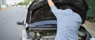
Lighting devices are extremely important on cars, and this applies not only to headlights, but also to signal lights. Turn indicators, side lights, brake lights - all this helps surrounding drivers to better distinguish the outlines of the car and predict the driver’s maneuvers.
When the brake lights on a car do not work, this can lead not only to a collision, but also to a fine if the malfunction is noticed by the traffic police.
It is better to fix this problem immediately after it occurs; moreover, most often the reasons why the brake lights do not light up are quite trivial, and the malfunction can be easily fixed without contacting a service center.
Why don't the brake lights light up?
Almost any problem with electronics in a car can be solved in the same way. You need to look for the problem either in the device itself, which is faulty, or in the power supply system to it. The situation is similar with the main reasons for the breakdown of brake lights. If they do not light up, it may be due to one (or several) of the following reasons:
- Problem with the brake light fuse: its oxidation or failure;
- Malfunction of the lamp(s) installed in the brake light;
- Problem with the brake light activation mechanism when pressing the brake pedal;
- Oxidized contacts in the socket for installing the brake light lamp;
- Damage to electrical wiring.
As you can see, among the problems listed above, only one can cause serious problems for the driver if he wants to repair the brake lights himself, and we are talking about wear and tear on the electrical wiring.
Modern cars are equipped with dozens of electronic devices, and a worn, torn or improperly clamped wiring harness can cause your brake lights to turn off. If none of the troubleshooting steps below resolve the problem, it is most likely a wiring issue.
In such a situation, you will need to find a detailed plan for the car's electrical wiring and check with a tester for the presence of voltage in the sections, and after finding the problem, solder or replace the wires.
But don’t rush to get a tester, most often the brake lights don’t light up due to much more mundane faults, the elimination of which will be discussed below.
Checking brake lamps and brake light sockets
It is advisable to start troubleshooting the brake lights by checking the lamps. To do this, you need to open the trunk and remove the taillights, after which you can get to the brake lights. Depending on the make and model of the car, the method of removing the taillights will vary, and on some cars you can even get to the brake lights without this procedure.
The most reliable way to check whether the cause of the malfunction is burnt out lamps or oxidation of the contacts in the socket for installing them is to replace them with new ones. It is not always possible to determine by eye whether the lamps have burned out or not, so it is better to acquire new light-emitting devices in advance and install them.
If it turns out that no new copies of the required size were found, you can remove the working lamps from the turn signal indicators, side lights or other lighting devices of the car.
Try them, and if the problem is solved, then it is enough to buy new lamps and replace them so that the brake lights begin to work as before.
Important: Some car models are designed so that if one brake light fails, the second one turns off automatically. Accordingly, when checking, it is better to screw the lamps into both brake lights to make sure that the problem is not related to their malfunction.
When replacing the lamps does not resolve the problem, you need to make sure that there is no oxidation of the brake light “cartridges”. Also check that the sockets are connected to the vehicle's wiring. If there is any doubt about this, you can disconnect the wiring contacts, clean them with fine-grit sandpaper, lubricate them with electrically conductive grease and reconnect them.
Please note: To check the sockets after performing the above manipulations, use new (removed from other lighting devices) lamps, since it is possible that previously installed lighting devices have become unusable simultaneously with damage to the contacts.
Problem with fuse for brake lights
In a car's electrical circuit, a malfunction often occurs due to fuses that may fail. There are several ways to check fuses in a car, including visually or using a multimeter. In this case, there is one “household” method for diagnosing the brake light fuse.
You can make sure that the brake lights are not on due to a failed fuse. To do this, just start the car and press the horn.
If the sound is heard, then the fuse is good and the brake light malfunction is due to another reason.
If there is no sound, you need to determine from the fuse block diagram which one is responsible for the brake lights and horn, and then replace it.
Please note: This verification method is not suitable for all car models. On some cars, different fuses are responsible for the brake lights and horn, and if one of them fails, the other will continue to work properly.
Brake light switch malfunction
When the driver presses the brake pedal, the force is transmitted to a mechanism commonly called the “frog” or limit switch, which is also the brake light switch. When you press it, the brake lights come on; therefore, if for some reason it stops working, the brake lights will not turn on.
In total, there are 2 main reasons why the limit switch fails:
- Oxidation of contacts;
- Formation of carbon deposits and corrosion.
As you can see, the faults are quite similar, and they are eliminated in the same way - by cleaning the “frog” or replacing it.
To remove the brake light switch you will need to remove the pedals. Then it can be easily found under the brake pedal, and the limit switch can be removed by simply turning it counterclockwise by 90 degrees.
When the “frog” is dismantled, disconnect the wires from it and try to close them “manually”.
If as a result of these manipulations the brake light comes on, it means that the brake light switch needs to be replaced or repaired.
If you decide to tinker with the limit switch, repairing it is quite simple. It is enough to understand the device, clean all contacts with alcohol-based liquid and then lubricate them with electrically conductive lubricant. After this, the “frog” can be assembled, installed and tested.
Important: Please note that if your car's brake lights are constantly on, there is a high probability that the problem is also related to the limit switch. The method for troubleshooting in this situation is no different from the option given above.
(444
Push
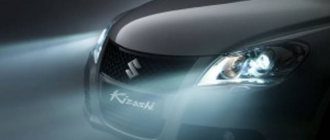
Safety in front of oncoming traffic can be ensured in several ways: bright head optics, additional DRLs, standard fog lights, etc. If your car has high-quality, clearly visible lights on the rear, you don’t need the device. If the light is not enough, you can either install a more aggressive light source or install this device. In the first case, you risk receiving the curses of blinded drivers. In the second, with proper installation, this will not threaten you.
Power supply for LEDs in a car
LEDs need stable power. With voltage surges in the on-board network, they will quickly fail. It is necessary to stabilize the voltage or current. So let's look at the circuit of the simplest linear voltage stabilizer.
To make LED tail lights with your own hands, you need to provide them with power. To do this, you need to buy a microcircuit like L7812, or a domestic complete analogue of KR142EN8V, or an adjustable LM317, from a radio parts store. Below is a diagram of the connection of the first microcircuit; for example, an LED strip was used as a load.
In this design without a radiator, the microcircuit can withstand a current of up to 1 Ampere; it is advisable to mount it on an aluminum radiator; you can find them in power supplies and on motherboards, as well as other electronic devices. An ordinary copper or aluminum plate with a thickness of 1 mm or more, the size of a matchbox, is perfect as a radiator.
Using LM317, you can get different output voltages; by the way, if you power the LEDs with a slightly reduced voltage, you will practically not lose any brightness, but will significantly extend their service life. You can see the connection diagram and resistor values below.
Selection of stabilizer
Use a stabilizer for each flashlight separately. If you work with low-power circuits: illumination of the glove compartment, interior or dashboard, then one stabilizer is enough. To determine the number of stabilizers for a specific circuit, calculate the total current consumption of LEDs; to calculate the consumption of strips, see the table.
| Tape power depending on diode density | ||
| LED type | Diodes on 1m | Power, W |
| SMD3528 | 60 | 4,8 |
| SMD3528 | 120 | 7,2 |
| SMD3528 | 240 | 16 |
| SMD5050 | 30 | 7,2 |
| SMD5050 | 60 | 14 |
| SMD5050 | 120 | 25 |
To get the current, divide the power by the voltage:
14W / 12V = 1.16A
Now you know how to make LED tail lights and, by analogy, you can completely re-equip your car with LED lighting and backlighting.
You must make the choice between LEDs and strips for yourself; I note that with the help of individual LEDs, especially if they are in SMD design, such as 2835 or 5050, you can perform much more complex tasks than with strips, making a unique design of the lamps.
The brake lights on the VAZ-2112 do not light up or work, why?
On all cars of the Tenth Family, the power lines for the lights contain many elements. There are lamp health relays, switches and fuses.
Therefore, if the brake lights on a VAZ-2112 do not light up, you need to check the entire chain. But the reason may look simple: sometimes the lamps do not turn on because the socket does not contact ground.
Circuits are easy to analyze, but finding the cause of a breakdown is difficult. Let's look into the details.
If one of the lamps does not light, it is simply replaced. See the example in the video - you need a P21 W
Standard version of the brake light operating diagram
Power is supplied to fuse F17 from the battery, then the current goes to limit switch contact 11, and then, if the limit switch is closed, a circuit is formed with the filament of lamps 7. But note: part of the circuit is relay K1, more precisely, its contacts 5 and 4.
Basic network diagram
If the brake lights do not light up, on the VAZ-2112, as on all Tens, check one fuse. It is called F17 and is located in the mounting block to the left of the driver.
Main mounting block
It is important to know: voltage is always present at one of the fuse terminals. Check it out!
A few words about the “serviceability relay”
The lamp health relay is called K1, and it is the largest in the mounting block. If you remove this relay, then when you press the pedal you can dial the voltage at terminal 5 (but not 4). Look at the diagram again, and it will become clear what we are talking about.
The largest relay in the block
All relay contacts are numbered. Check the voltage at the block terminals:
- 6 – “mass” potential;
- 2 – voltage “+12”, but only after turning on the ignition;
- 5 – “+12” by pressing the pedal;
- 4 – the terminal rings like a ground tap.
If the potential “0” is not generated at terminal “4,” it means that the lamp filaments are burnt out or there is a break in the wiring. Now consider something else: the ground potential has been detected, but the lamps do not light. This is where suspicions of a short circuit arise.
We turn on the brake lights forcibly
Relay K1 is successfully replaced with a pad with jumpers. In Fig. 1 just shows its diagram. If there is no such platform, you can temporarily close contacts 4-5. First, check everything mentioned above.
How to and how not to check the “0 Volt” potential
Let’s agree right away that we only work with a voltmeter. Voltage “+12” is caused by connecting one probe to ground. The presence of potential “zero” is checked differently: any of the probes is connected to a terminal with positive voltage, and then the second probe is connected to the wire being tested.
How to connect a voltmeter
Consider the error: one probe is connected to ground, the second to the terminal being tested, and vol. Here they conclude that there is a “mass” potential, but this is wrong! If the contact with ground is broken, the device will also show “0”. That is, the number “0” does not contain information.
Impressions of use
In clear, sunny weather,
the signal strip is practically invisible. I couldn't even take a decent photo. On the other hand, the best visibility of your car is in such weather. So there seems to be no need for a subject.
At night in moderate lighting
the device is visible in the form of a lane transverse to traffic on the road (the standard PTF had to be covered up, it exposed the photographs). This stripe is noticeable only when you are sufficiently close to the car - from 7-10 meters.
To create conditions of complete darkness
I had to go out of town. In this case, the laser stripe is clearly visible at a sufficient distance from the source - about 70 meters.
When installed inside the cabin, one drawback was discovered: the laser is barely noticeable reflected on the inner surface of the glass.
In foggy or rainy
We have not yet been able to test the brake signal: the weather in the capital is beautiful and bad weather is not expected. If weather conditions change, I will immediately record and post an invoice. Based on videos from the network, we can conclude that the laser, in addition to the stop line on the road, also shows up as an illumination of the luminescence spectrum.
Drivers behind you see a bright red triangle of light. The result is increased attention and increased caution.
The only nuance
when using such a device, drivers may react to an unusual end of the world... I hope that, after all, seasoned drivers will perceive such a brake light properly.
Conclusion
A fog brake light for a car is a device that allows you to increase the level of vehicle safety. This element has a lot of advantages, with a minimum number of disadvantages. The average cost of a laser fog brake light is approximately 1990 rubles.
- Price: $8.36
Recently I became a regular at a respected automotive forum, where I discovered a lot of interesting information about the peaceful use of the irrepressible energy of car enthusiasts. In one of the thematic communities there was a heated discussion about successful and not so successful purchases of automobile paraphernalia in China. One of the topics was dedicated to the Hero of this review - a universal laser fog light (brake light) for a car
.
The beam of this flashlight serves as an additional visual and psychological (!) warning for drivers following your vehicle about a safe driving distance. My first reaction: Come on, another overexposure from the Evil One!
.
But
studying the subject on the Internet convinced me that there is never too much security.
If German manufacturers introduce such a device into the bodies of their horses, this is a clear reason to think about it. Ordered from DX.COM for $8.36.
Here's what it says on the seller's page:
Description of the electrical circuit
For the practical implementation of the above circuit, a multivibrator is required, the basis of which is the DD1 K561LA7 microcircuit and the DD2 K561IE8 counter microcircuit. Using the first microcircuit, pulses are created that turn on the LEDs. Thanks to the counter chip, power is switched for certain groups of LED lights.
Transistors VT1-VT2 are used as amplifiers, which open due to the voltage coming from the meter leg. Capacitors C2 and C3 play the role of power filters. By selecting the capacitance of capacitor C1, you can decrease or increase when the LEDs are switched. To mount the LED stop structure, a printed textolite board with dimensions of 37 x 50 mm is best suited.
PCB dimensions
PCB dimensions
This design requires minimal current and hardly heats up. This makes it possible to make the assembly that controls the LEDs in the same brake light housing. In this case, the power can be connected to the removed standard lamp.
Below is a diagram that is easy to implement.
Implementation of LED blinking
According to this scheme, groups of LED light bulbs are connected to pins Out1 - Out3. How many LEDs there will be in total depends on the power supply. If there are too many light bulbs, then you need to take into account what kind of power is supplied to the circuit from the on-board network, which is 12 V. KT972A transistors must be protected using heat sinks. If desired, you can replace the KT972A transistor with a pair of less powerful KT315 transistors and a powerful KT815 element or similar elements.
Parts DD1.1 and DD1.2 included in the circuit play the role of a generator, which serves to supply pulses to the input of the K561IE8 counter. Similar to the previous case, control pulses for transistors are generated using a counter. When selecting resistance R6, its nominal value should be at least 1 kOhm. You can use a printed circuit board to create running lights. Thanks to the hanging installation, the design is miniature in size.
Miniature board dimensions
Naturally, the LED bulbs are placed directly on the brake light panel, since the circuit board is too small to fit LEDs on it. You should remember about reliability, so it is necessary to ensure maximum protection of electrical connections and contacts from moisture. To provide power to the additional stop, it is connected to the wiring of the main stop in the trunk. It is possible to connect lighting devices to the board.
If everything is assembled correctly, no additional configuration is required. Diode brake lights begin to work immediately after connection.
Installing an LED strip in the rear lights of a VAZ 2110
LEDs have become very popular recently. They are installed not only in the car interior, but also in the optics. Another photo report on installing LED strips in the rear lights of a car. Currently, there is a large selection of LED strips in stores, so I will show two different installation options:
Installing LED strips in car taillights
1.First of all, remove the rear lights of the VAZ 21102. Very carefully peel off the glass; for this you can use a blade, a stationery knife and a thin screwdriver. You can heat it with a hair dryer. 3. Then we clean and dry the reflector 4. We create a form for placing the diodes, for example, with sealant or adhesive gel. We install a 30 cm LED strip of 18 diodes. Price 170 rubles. We fix it inside the headlight. We glue the headlight glass back. Connecting the diodes to the dimensions. The final version and the option of installing the diodes in the rear headlights as a whole:
Installing strip diodes in the rear optics of a car
I chose diodes in silicone on double-sided tape because:
- Cheaper
- Brighter
- Greater viewing angle
- On one piece there are 3 diodes in one diode there are 3 crystals, that is, there are already 9 diodes in one piece
- You glued a piece and you don’t even think about soldering the diodes together.
I bought 80cm yellow and 120cm red.
xn--2111-43da1a8c.xn--p1ai
We make LED headlights with our own hands. Details about each step
A master class on how to make LED headlights with your own hands will probably be of interest to many car enthusiasts. Because every driver, as a rule, wants his car to look unique and original. And external elements of tuning are not only an interesting and exciting activity, but also a way of artistic self-expression, further emphasizing the advantages of the car and its owner. On some features, it would seem that you spend a minimum of time, money and effort, and as a result you get maximum efficiency and originality of the solution. DIY LED headlights, of course, belong to such car improvements and modifications available to every driver. Which in no way detracts from the merits and moral satisfaction of the work performed. LED tuning Car headlight modification is a fairly common method of tuning. Because as soon as you change the light, the appearance of the car changes. You can modify the optics using various methods. Insert xenon, LEDs, make eyelashes, “angel eyes”. What to choose is the owner’s task. And anyone can cope with the task, even a beginner. Let's look at several ways to improve the headlights for your car. Do it yourself: Of course, you can go to the nearest service station where an electrician is available. There, for a certain price, all your artistic ideas will be brought to life. However, this will most likely result in a tidy sum. And some users prefer to work independently - after all, you and I are not looking for easy ways! So, let's get started with the work. What is needed to get the job done? To be fair, it should be noted that not only the front end can be improved, but also the foglights, turns, and all rear optics. To carry out the process you need:
- LEDs + resistors (color - at the request of the designer, sizes - small and medium);
- soldering tool;
- sealant;
- insulating tape;
- drill.
Let's start by removing the headlight from its location.
We peel off the sealant. Let's analyze the design. With a marker we mark the places on the case where the diodes will be inserted. We must attach resistors to the diodes to protect against short circuits. We use a soldering iron to solder it into the circuit using connecting wiring. We check the operation of the LEDs. We connect the lamps inserted into the designated sockets. We seal it with sealant and install it in its place. Instead of individual diodes, you can use heads or ready-made LED strips. Angel eyes For cars with rounded optics, angel eyes (like on a BMW) are a rather original and acceptable solution. To carry out the work we will need: plastic tapes (like on blinds), LEDs, pliers, a jar for formatting, sealant for filling. First, soften the plastic (in boiling water). And then we bend the ribbons around a round tin container. We drill holes at the ends of the tapes. We connect the LEDs with resistors (1 resistor for 2 LEDs, for a total of 8 diodes) and insert them into the rings. To make the light brighter, you can make notches in the plastic. Let's check how the innovation works. We insert a plastic stick with diodes into the headlight. Fill it with sealant and insert it into the dislocation location. Let’s check the work again. This is described in more detail in the article: “How to install angel eyes with your own hands.” LED stripWe buy LED strip. For rear optics - a consumption of several meters. Please note that it is designed for a voltage of 12-15 Volts, just for a car. When purchasing the tape, it is advisable to check it for working condition. Next, we measure the size of the circle in the taillight and try on a ring of LEDs for it. Please note that the tape is marked every three lamps. In these places it can be cut painlessly. Cut according to the size measured by the headlight. To complete the circle, we pierce the edges on both sides of the piece of tape with a wire. We check again for functionality by connecting the structure to electrical power. Then, you can insert the lighting segment without completely disassembling the headlight. Simply remove the lamp and use the hole for the base. We carefully insert the resulting circle of LEDs inside the taillight structure through the hole in the lamp. There it should take the appropriate shape (straighten it if necessary with a long thin screwdriver). We adjust the position of the new lighting element. Ideally, the tape should lie in a circle, securely without gluing. Next, we drill holes in the lamp base and run wiring into them. Seal with sealant. Insert the main lamp. We connect the diodes to the wiring using a soldering iron (do not reverse the polarity, otherwise you will not see any light). So, all 4 stop lamps can be circled. It looks very original, especially in the dark. AutoFlit.ru
Advantages and disadvantages
The number of advantages of the signaling device is simply impressive:
- No one should be surprised by the first and most obvious advantage of a laser brake light - it significantly increases driving safety.
- The laser beam is capable of providing maximum brightness that exceeds the light of LED and xenon elements.
- The design of the laser brake light allows you to adjust the angle of the beam, thereby changing the distance of the warning signal.
- The laser brake light for the car is placed in a shockproof and moisture-resistant housing, protecting it from the negative effects of external factors.
- Signaling elements withstand sudden temperature changes well - this is especially true for Russian weather conditions.
- The laser signal housing is made of aluminum, which makes it extremely resistant to corrosion.
- Signaling components are easy to install - even novice motorists can handle this without much difficulty.
- The laser fog brake light is universal - it can be installed on any type of vehicle.
- There are several options for mounting the signaling component, which does not make it tied to a specific location on the body.
- Due to its compactness, the laser brake light fits perfectly into the overall stylistic concept of the exterior.
- Low price.
- Economical in terms of resource consumption.