Comprehensive tuning
Quite often, motorists who improve their dashboard with their own hands modify several instruments at once or the overall lighting of the dashboard to make it look more stylish. In this case, it is better to prepare in advance the same templates for the instrument scales and the same color LED backlights. In the same case, if you do not have access to LEDs of the desired color, you can get by with ordinary white LEDs and simply stick a translucent film of the desired color to the desired places. This film will be a regular light filter, and you will achieve the same effect as when using LEDs of different colors.
Schematic diagram of the device
The device is assembled on CD4521, CD4026 and CD4011 microcircuits. All these microcircuits, as well as a quartz resonator and indicators, can be purchased on the Chinese website AliExpress (type in the search, for example, CD4521, and you will get several offers). In any case, the author purchased them through this site, with postal delivery.
Measuring the pulse frequency at the output of the speed sensor showed that at a speed of 10 km/h the frequency fluctuates between 27-30 Hz. That is, with an input frequency of 27 Hz, the speedometer should show “10”. It turns out that the measurement period should be 0.37 seconds.
The master oscillator is made on a D1 chip of the CD4521 type. This chip contains logic elements for constructing a multivibrator circuit and a 24-bit binary counter. The multivibrator is made of quartz, with a quartz resonator with a frequency of 4.194304 MHz.
As a result, a logical one appears for the first time at pin 12 D1 after 0.125 seconds, at pin 13 after 0.25 seconds, at pin 15 after one second, at pin 1 after two seconds.
If you combine pins 12 and 13 with a logical element “2AND-NOT” (D5.3), then a logical zero will appear at its output after 0.25+0.125=0.375 seconds. That is, a little more than 0.37 seconds, which, given the permissible error of the speedometer, is quite acceptable.
The measuring and indicator counter is made on three CD4026 microcircuits, each of which is a decimal counter with a built-in decoder for a seven-segment LED indicator with a common cathode.
Input pulses must be applied to pin 1. The input can be closed by applying a logical one to pin 2 of the microcircuit. And you can turn off the indication by applying a logical zero to pin 3.
Thus, to start the measurement period, you need to apply zeros to pins 2 and 3. In this case, the input will open and the indication will turn off. To start the indication period, you need to apply units to the same inputs - the input will close and the indication will turn on. Therefore, the low-order counter (D2) has pins 3 and 2 connected.
And for the rest of the counters, pins 2 are connected to a common minus, so that their inputs are always open.
Rice. 1. Schematic diagram of a homemade digital speedometer (frequency meter).
There is also pin 15 - a normal zeroing input; to reset it you need to apply a unit to it. Another pin 5 is a transfer pin for cascading; the counter input of a higher-order digit is connected to it.
The cycle begins with the zero state of the counter D1 and the measuring counters. At the moment of zeroing, the RS trigger D5.1-D5.2 is set to a state with a logical zero at pin 3 of D5.1. At the same time, the measuring counter counts the pulses arriving at its input from the speed sensor. And the indicators are off.
After 0.375 seconds, a logical zero appears at the output of D5.3, and the RS flip-flop D5.1-D5.2 switches to the opposite position. Now at pin 2 D2 and pins 3 D2-D4 there is a logical one. The meter input closes and the indicators turn on. The indication period begins.
After another 1.625 seconds, a logical one appears at pin 1 of D1. The measuring counter is reset, the indication is extinguished, counter D1 is reset, and the next measurement period begins. Thus, the measurement period lasts 0.375 seconds, the indication period lasts 1.625 seconds. And the total cycle is 2 seconds.
If you want to speed up the work, you can connect pin 15 of D1 to inputs D5.4 and R6 instead of pin 1. But then, subjectively, the speed indication is not so clear. Although, the readings change faster.
Is replacement always necessary?
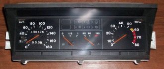
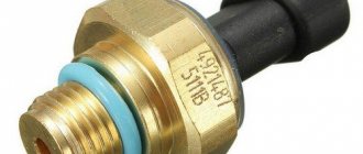
The information transmitted by the speed sensor to the ECU is very important; the readings of the instruments discussed above depend on it.
This information also affects the quality of the fuel mixture supplied to the cylinders, the idle speed, the stability of the engine and the amount of fuel consumed. If the sensor malfunctions, the electronic unit will not be able to determine whether the car is moving or stationary. In this case, floating speeds are observed, the engine begins to stall, and fuel consumption will become much higher.
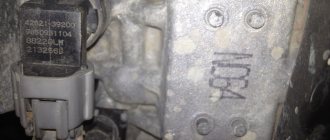
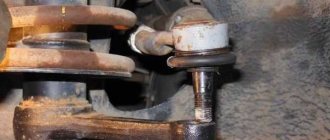
Carrying out a vehicle inspection is available to every car enthusiast. To find a fault, you need to know where exactly it is located in the VAZ-2110. The sensor is located in the engine compartment under the hood, in the engine compartment. Nearby is the exhaust manifold (and on the VAZ-2112 there are 16 valves, it is located in the upper part of the gearbox, fully visible and accessible from the engine compartment).
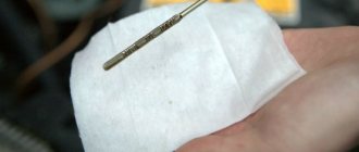
The wires rub against the commutator and this can cause damage. Sometimes it is sufficient to isolate them and position them so that there is no contact with the collector.
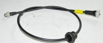
Don’t forget about a broken cable, which can cause a breakdown. If this problem is absent, then you need to look for it in the sensor itself or in its drive.
To successfully replace the VAZ-2110 speed sensor, the speedometer's functionality is first restored.
How to make an LED speedometer from a stepper motor
In the article, using the example of a Peugeut 504 car, we will look at a diagram of how you can make an LED speedometer with your own hands. The device turned out to be quite original, and the assembly process is not that complicated. The device can operate thanks to the ABS sensor, which determines the speed. This sensor works very simply; when a metal object passes in front of it, it generates an electrical impulse, which is then sent to the electronics. Next, based on the frequency of these pulses, the vehicle speed or engine rotation speed is calculated. Thanks to this scheme, you can also assemble a tachometer, as the author did.
Signals from the sensor must be converted into voltage; LM2917 is used for this purpose. As the voltage increases, 30 LEDs will turn on in series, which are connected through three LM3914 type microcircuits.
Specifically in this article, the author replaced the ABS sensor with a stepper motor, because it can also generate pulses. In addition, such an engine also produces voltage, which increases with increasing speed. In this regard, there is no need to use the LM2917 voltage regulator.
Materials and tools for manufacturing: - stepper motor (can be found in an inkjet printer); - wires; - soldering iron with solder; — LM3914 microcircuits; — trimming potentiometer at 47 kOhm; — 31 LEDs; - thick paper for creating a display (cardboard); — two 1 kOhm resistors; — three 2.2 kOhm resistors; — electrolytic capacitor 470 uF/25V; — two 100 nF polypropylene capacitors; - scissors and other small items.
Speedometer manufacturing process:
Step one. Installing a speed sensor
In order to make a sensor, you can use infrared detectors and LEDs, various sensors, and so on. The author used a stepper motor from an inkjet printer for these purposes. Of the two, the largest one was chosen, which produces the most power and signals. The most difficult thing is to connect the motor with a cable, that is, install a stepper motor instead of the previous dial speedometer.
In order to connect both shafts, a piece of copper plate was used, which was cut to the desired size. It is inserted into the grooves and thus ensures excellent connection between the shafts. The engine itself also needs to be well secured, since it is heavy and will jump around the cabin when driving, and this can damage the design. You can drill a hole in the motor housing and then screw it to the desired location using a bolt and nut. Step two.
Electronic circuit After installing the stepper motor, there will be 4 wires that need to be connected correctly. The author took the first wire as a signal wire, and the second as a ground wire. During preliminary testing, the engine produces about 48 V. If you connect the motor to the transmission and spin it to the maximum possible value, it produces 28 V. In this case, we can conclude that the voltage increases linearly with the rotation speed, and this is very good and this voltage is enough for operation speedometer.
The 12V voltage comes from the battery and the ground from the transmission. The signal is generated by a stepper motor. The fifth input of the LM3914 chip will have to withstand a voltage of about 35 V. To calibrate the signal, a 45 kOhm trimming potentiometer is used. The speedometer is calibrated using GPS, which is in your phone or navigator.
LM3914 chips are LED display drivers. Each of these drivers is needed to control ten LEDs; this can be either segment or point mode. Modes are switched according to the attached instructions. As for the 7809 (9V) controller, it regulates the voltage.
Step three Assembling the speedometer
There should be 31 LEDs in total, the light is selected individually, the main thing is that they are bright.
The author used bright white LEDs. You can make the tape multi-colored, for example, put red ones at the end, which will indicate a high speed of movement, and green or blue LEDs at the beginning. The first LED should be lit continuously when +12V power is connected.
The remaining 30 will turn on sequentially as the vehicle speed increases. The base for the LEDs is made of cardboard; rectangular compartments are cut out opposite them, onto which thinner paper is then glued. When LEDs work, light will pass only through thin paper, creating the effect that can be seen in the photo. The paper can be painted any color. Naturally, later this entire structure is installed instead of the insides of the old dial speedometer. Partitions need to be made between the diodes so that the light does not spread throughout the entire strip. It is best to use aluminum, it will reflect light perfectly.
That's all, now all that remains is to install the speedometer and connect it. In the photo you can see that the author replaced the tachometer with such a homemade product. Source
Become the author of the site, publish your own articles, descriptions of homemade products and pay for the text. Read more here.
GPS Speedometer that is suitable for older cars without OBD-2
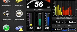
The device under review will most likely be useless for most motorists who own cars that are not exactly “shaggy” model years, since there are many options with much more interesting functionality that are connected via the OBD-2 interface. Also, it is unlikely to be needed if the standard speedometer in the car works normally. Also, almost any smartphone with GPS and most video recorders can perform similar functions. I believe that, in principle, it can only be in demand in situations very similar to mine. The background and the story itself are under the cut. Why do I need this
So, there is a certain car “A”, although why intrigue - “Audi”, produced in those distant times when cars were not yet smarter than their owners, did not have full-fledged “brains” in the modern sense, and the OBD-2 interface, accordingly... He appeared in the family a long time ago, back in his youth. The car is in good technical condition and is expensive, like a memory, and today it is very cheap, which excludes thoughts about the advisability of selling it. Lives in the garage at the dacha and is occasionally used as a spare. So, one day the old man became capricious and refused to show anyone the speed of his movement. The fact that this whim should not be ignored was soon reminded by kind people who spent time in the bushes not far from the sign with the number 40 in a red circle. Having exchanged some amount of Belarusian rubles for “All the best!”, I thought about repairing the speedometer. Diagnostics, without going into details, revealed a problem on the side of the gearbox, which otherwise worked properly, and therefore was absolutely not conducive to disassembling it. Having tried to use a smartphone to measure speed, I realized that it was inconvenient for me. And not all family members who use this car from time to time use smartphones (imagine, this happens). The concept of the necessary device was formed: Plug & Play, maximum ease of use and minimum cost. These are, in fact, the main prerequisites that prompted me to purchase this particular speedometer.
Directly about the purchase
The price from the seller at the time of purchase was $25.5.
Plus, there were $2 coupons for purchases over $15. I haven’t found any analogues cheaper than $23.5. Payment and speedy, almost breaking the record I had previously recorded, delivery to the Republic of Belarus in 18 days
2016-01-14 user_event_added Parcel added 2016-01-14 Finn post. Posti. The item is not yet in Posti, VANTAA 2016-01-14 Finn post. Posti. Item has been registered, VANTAA 2016-01-16 Finn post. Posti. Item has arrived to warehouse, HONG KONG 2016-01-17 Finn post. Posti. Item has departed from the warehouse, HONG KONG 2016-01-19 Finn post. Posti. The item is on its way to the destination country, LUXEMBOURG 2016-01-26 Finn post. Posti. The item is in transport, HKI VANTAA, ULKOMAANTERMINAALI 2016-01-26 Belarus Post; RU: BelPochta Sending an item from an exchange office, HELSINKI 2016-01-30 Finn post. Posti. The item has been submitted to customs clearance in the destination country, Ulkomaa/Foreign country 2016-01-30 Finn post. Posti. Item arrived in the destination country, Ulkomaa/Foreign country 2016-01-30 Belarus Post;RU: BelPost Received at the mail processing area, MINSK PI 2 2016-01-30 Belarus Post;RU: BelPost Passage through the customs zone, MINSK PI 2 2016-01-31 Belarus Post;RU: BelPochta Sending the item to a local office, MINSK PI 3 2016-01-31 Belarus Post;RU: BelPochta 08. Transferred from (200400) to (220006) Minsk - 6 2016-01-31 Finn post. Posti. In transit, Ulkomaa/Foreign country 2016-02-01 Belarus Post;RU: BelPochta 06. Received at the mail processing area (220006) Minsk - 6 2016-02-01 Belarus Post;RU: BelPochta 09. Delivery attempt (220006) Minsk — 6 2016-02-01 Finnish post. Posti. Delivery attempt made, addressee not reached, Ulkomaa/Foreign country 2016-02-01 Belarus Post;RU: BelPochta Handed over, MINSK - 6 2016-02-01 Belarus Post;RU: BelPost 10. Delivered, handed over (220006) Minsk - 6
The kit includes a two-position rubber stand for holding the speedometer on the panel while standing or lying down, fairly adequate instructions for switching modes in English and a cable with micro-Usb for power, 182 cm long. In the store description, the kit should also include a darkening film for glass called Reflection Film. For some reason they didn’t give it to me, but... I wasn’t going to glue anything onto the glass anyway, it didn’t upset me. If you use the speedometer in projection mode on the windshield, on a sunny day it would not be superfluous.
Dimensions
The speedometer housing is neatly sealed, and therefore it was easy to overcome the temptation to dissect it. It should be something like this inside
In progress
After power is applied (ignition is turned on), satellites are searched for about a minute, then the speedometer starts working in accordance with the previously set settings. When the power is turned off, all settings are saved.
Short presses on the right button — select one of three speed display modes. The numbers on the screen mean: 111 - normal display 222 - inverted mirror (for projection onto the front window) 333 - non-inverted mirror (for projection onto the rear window) Long press on the right button - select miles or kilometers. The “up” and “down” buttons are used to set the speed limit, if exceeded, a shrill and nasty squeak will be heard. When you stop driving without turning off the engine, for example at a traffic light, the screen alternately displays the distance traveled and the travel time. The aforementioned squeak, also after every hour of continuous driving, reminds the driver that it would be a good idea to stop and stretch his rolls.
The speedometer readings at constant speed are correct in both miles and kilometers per hour. There is some inertia when accelerating and braking, it lags behind the standard speedometer by about 2 seconds, but a little later I noticed that the same thing happens in Navitel in a smartphone. The video shows a comparison of the GPS speedometer readings with the readings of a working standard MB speedometer from the USA (arrow in miles, numbers in km/h)
Conclusion:
The device works great and fully met my expectations. The absence of any need for any manipulation during use earned the greatest approval from my elderly Parent. Well, whether you need it is, of course, up to you to decide.
Where to start tuning
No matter how you plan to improve your car’s dashboard, first prepare the necessary tools:
Tools for disassembling the dashboard Industrial hair dryer Utility knife or sharp blade Required wiring and controls Soldering iron and solder
The rest of the necessary tools and materials will vary depending on what you are going to do with the dashboard. You may also need specific tools if disassembling the panel requires using non-standard techniques and non-standard tools. Find out in advance what tools are needed to remove the car trim and unscrew those elements that need to be replaced or modified.
Disassembling the dashboard
Experts recommend carrying out any work in a dry, dust-free room. This is a fairly important point on which the overall success of our venture depends. Firstly, dust can prevent us from evenly gluing various colored films to change the color of the instrument lighting on the panel, and high humidity will simply ruin the wiring. You should carefully remove the trim on the dashboard of your car in order to gain access to those controls or monitoring the condition of the car that you want to work on. If you are going to change the scale on the instruments, we advise you to remove the arrows very carefully. A simple marker is ideal for this, which marks the junction of the arrow using a dash or dots. If the arrow is soldered, you can use a soldering iron and heat the tin that holds the arrow to the coil. However, do not forget that the arrow will still need to be installed back, and in order to do this correctly, you need to mark the connection points, because otherwise calibration can only be carried out in a car service center.
How to improve your dashboard
Once you've disassembled the dashboard to the point where it can be worked on, it's worth stopping and rethinking what you're planning to do. You also need to check whether your modifications will damage the car and if everything is in order, then you can continue. After this, you can do almost whatever you want with your dashboard, but with the abundance of different possibilities, you often start to get lost, so let's look at several tuning options.