07/18/2021 4,975 VAZ Niva
Author: Ivan Baranov
As you know, engine performance is largely determined by the state of operation of the ignition system. Problems in the functioning of the latter can lead to the motor starting to work intermittently. From this material you can learn how to remove the ignition switch on a Niva with your own hands and adjust it, as well as what needs to be taken into account during this process.
[Hide]
How to replace the ignition switch of a VAZ-21213, VAZ-21214 car
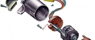
To turn the car's electrical circuits on and off, use the ignition switch or simply the ignition switch.
A mechanical anti-theft device is installed in the ignition switch, blocking the steering wheel rotation.
The anti-theft locking rod extends when the key is placed in the “parking” position and removed from the lock.
After this, turn the steering wheel so that the rod fits into the groove on the steering shaft, locking it.
The locking rod is recessed, releasing the shaft, when the key is turned from the “parking” position to the “off” position.
The closure of the ignition switch contacts at various key positions and the switched circuits are shown in the table.
The power supply circuits for the horn, brake light, hazard lights, cigarette lighter, lamp, plug socket for a portable lamp and high beam headlights are always turned on (regardless of the position of the key in the ignition switch).
Removing the ignition switch
Disconnect the negative cable from the battery.
We mark the wires suitable for the contact part of the ignition switch and disconnect them.
Using a slotted screwdriver, unscrew one screw securing the ignition switch to the steering column bracket on the left and the second, located below, to the right of the first.
With the ignition switch key in position “0” (“off”), use a slotted screwdriver with a narrow blade to push the ignition switch lock through the hole in the side wall of the steering column bracket.
Pull it towards you and remove the ignition switch.
To replace the contact part of the ignition switch, pry it with a screwdriver and remove the retaining ring.
The retaining ring may come off.
We take out the contact part of the ignition switch.
When installing a new contact part, turn its rotating part counterclockwise with a slotted screwdriver until it stops.
We remove the key from the ignition switch and insert the contact part into the housing so that the wide protrusion of the contact part coincides with the wide cavity of the housing.
We assemble the ignition switch in the reverse order.
To make it easier to install the retaining ring, use pliers to bend the tendril
Source
Signs that it’s time to change the ignition switch
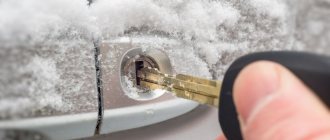
Early signs of a malfunction in the Chevrolet Niva ignition switch usually manifest themselves in the key jamming when it is turned in the cell. Slight jamming is especially common when turning the key from the “Ignition” position to the “Starter” position. Over time, the malfunction progresses and can lead to the key jamming in the cylinder.
At first, this problem can be solved by disassembling the lock and dripping oil into the cylinder, thereby reducing friction in it when turning the key. However, if the jamming progresses, then it is better to replace the lock before its cell jams tightly.
The presence of problems with the ignition switch is also indicated by the key slipping in the cylinder when it cannot be turned to the “Ignition” or “Starter” position. This situation also indicates a breakdown of the larva.
The second group of faults is related to the contact group. The Chevrolet Niva ignition switch is powered by several groups of energy consumers:
- in position “0” the car’s side lights can be turned on;
- in position “1” (“Ignition”) the high and low beams, turn signals and tail lights, the fuel pump, power windows, wipers, etc. work;
- in position “2” the starter starts.
In the case when several energy consumers, seemingly unrelated to each other at first glance, stop working, the problem may lie in a break, breakdown, or oxidation of the contact.
Such a malfunction does not necessarily require replacing the lock - you can repair the contact group by replacing damaged contacts. However, a problem with the contact group may indicate general wear and tear of the lock, so it is better to replace it entirely.
This is interesting:
Features of replacing the heater radiator in a Chevrolet Niva with and without air conditioning.
Where is the Niva Chevrolet fuel pump relay located?
Features of replacing the timing chain in a Chevrolet Niva with your own hands.
Connection diagram for the ignition switch Niva 2121
Schematic electrical diagrams, connecting devices and pinouts of connectors
The ignition switch in cars of the VAZ family fails from time to time due to weakening of the contact posts or burning of the contacts inside it. It also happens that the cams of a plastic roller are produced. You can disassemble the lock and clean it, but it’s better to just replace it with a new one, considering that it costs pennies compared to imported locks.
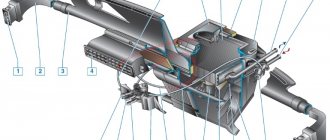
But if connecting the wires together did not result in the starter operating (or it did not turn on the first time), check the solenoid relay on the starter. The contact spots on it may also burn out, which will prevent the circuit from closing normally. Alternatively, you can use a screwdriver to short-circuit the two large terminals on the solenoid relay (before doing this, put the car in neutral and use the handbrake). When closed, the starter should begin to spin vigorously. If this happens, remove and change the solenoid relay. If the starter rotates “sluggishly” when it closes, you will have to remove it and check the condition of the brushes.
All operations are performed with your own hands, without the help of car service specialists. Moreover, the price of an ignition switch on a VAZ2106 is up to 100 rubles. To replace it, you will need to know the pinout of the wires coming from it, for which the editors of the site 2 Schemes.ru have prepared a large reference material.
The ignition switch is designed not only to start the engine - it performs several functions at once:
- supplies voltage to the vehicle’s on-board network, closing the circuits of the ignition system, lighting, sound alarm, additional devices and instruments;
- at the driver’s command, turns on the starter to start the power plant and turns it off;
- turns off the power to the on-board circuit, preserving the battery charge;
- protects the car from theft by fixing the steering shaft.
We repair the ignition switch on a Shevik. Try to remove it first))
Another breakdown has come, apparently I drove for a year without any breakdowns and that’s enough - my Shevik decided. Suddenly the key is blocked in the ignition, it is put in the first position (ignition), but the key does not turn to the second (starter), for the life of me.
I read the forums, this breakdown is quite common in the Chevrolet Niva, but I couldn’t find a proper manual anywhere, so I had to rack my brains myself right on the spot, that is, with my head under the steering column)) I immediately decided to record everything with photos and videos, so now it will be easier for you.
Apparently, having removed the casing from the steering column (there are 5-6 bolts on all sides and a rubber round coupling around the lock), we see the following - the lock itself is attached to the column using an additional bracket (on the left), which is attached to the lock mount itself with powerful and hemorrhagic tear-off bolts.
In general, the biggest problem, and not only for me, is to remove this damn ignition switch from the steering column. It is secured with 4 breakaway bolts, which are specifically designed to make it more difficult to steal a car.
Therefore, if you are not going to repair the lock itself, but simply decided to replace it, then do not forget to buy 4 tear-off bolts!
That is, they are easy to tighten; the caps have hexagonal key heads, which, at a certain tightening torque, break and a round cap remains. This is what we will need to unscrew, as many as 4 pieces. It turns out that putting it on is easy, but taking it off is difficult. And this is the true truth, believe me. For some it will take 10 minutes, for others it will take 2 hours, and they can’t remove it, but simply cut off the bolts with a chisel.
Here they are in the photo:
To unscrew them, we need a small chisel and a hammer, as well as a 5 mm flat screwdriver, preferably longer.
We unscrew it COUNTER-clockwise, adjust the chisel so that the angle of inclination is sharper, so that the force of the blow goes sideways, and not directly into the head. And we try to make a notch on the head of the breakaway bolt with a chisel; the most important thing here is to remove the bolt from the thread so that, once stuck, it begins to move.
In this way, moving the chisel, punching 3-4 mm at a time, we turn the bolt to the left until it loosens. Then you can unscrew it with your fingers or pliers if it still doesn’t turn well.
This is what such a bolt looks like, it goes to the cone. Let's take on the second one.
The most difficult one will be the one on the top right, it will be very difficult to crawl there, and then try to make a notch with a chisel, and then use a long flat screwdriver to rest against this notch and gently tap. Place the screwdriver at a “sharper” angle to the head so that the blow is kind of sliding, but also catches slightly.
By the way, we also shot a video on the third bolt, inspired by the success. Take a look, I think it will become clear how to unscrew them. Sorry, my friend’s hands are shaking, but the essence is still clear, it is described above))
Having unscrewed the bolts, you have practically won, now you can replace the lock itself without any problems, everything is quite simple, you disconnect 4 wires - red, blue, pink and black. True, you will also have to unscrew the lock itself from the second part of the fastening - using a Phillips screwdriver, 3 bolts.
There is a steering column locking stop in the center!
By unscrewing these 3 bolts, you can disconnect the ignition switch from the fasteners or (in our case) you can remove the “cylinder” of the lock and thereby repair it.
A lock without a key looks like this - stoppers stick out in all directions, which catch when turning and thus prevent the cylinder from turning inside.
When you insert the key into the cylinder, all the pins should be removed, thus they will not interfere with the key turning. In our case, we had 1 pin sticking out on the left, which clung and did not allow the “larva” to spin. We worked on it with a file.
Also carefully inspect the lock cylinder; it is quite possible that you will see burrs and even grooves on the upper side that were “trodden down” by the pressure pin running along its top. It turned out that for all the time (and the car is already 10 years old), he made his own move in the “body of the larva” (outer side), which ended in a dead end. And in this position the key was locked (position I - ignition). There, they also used a needle file to grind off the furrow it made; make the angle as sharp as possible. It is very difficult to explain, so think about how and what should work. The lock cylinder is made of soft material and in 10 years it will definitely wear out, the rear round pin “drills” its path. Point it the right way and you won't have to buy a new ignition switch.
For those who would be more interested in repairing the lock themselves, you can watch another short video on how to get the cylinder.
Oh yes, you can find locks with cylinders on sale (3 pieces - for the front doors and trunk) - the cost is about 1,300 rubles.
Or take it without the cylinders - it costs 900 rubles, but now you will have 2 keys - one to start the car, and the second to close/open the front doors and trunk. So repairing the lock, in my opinion, is a very good option, you win in 2 categories at once - you save money, and you will still have 1 key for everything, as before.
xtreme-trip.ru
Pinout of the ignition switch VAZ-2101 - VAZ-2107
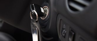
The ignition switch on these cars is located to the left of the steering column. It is fixed directly to it using two fixing bolts. The entire mechanism of the device, except for the upper part in which the keyhole is located, is hidden by a plastic casing.
On the visible part of the ignition switch housing, special marks are applied in a certain order, allowing inexperienced drivers to navigate the lock activation mode when the key is in the hole:
- “ ” – a mark indicating that all systems, devices and instruments that are turned on using the lock are turned off (this does not include the cigarette lighter, interior lighting, brake light, and in some cases the radio);
- “ I ” is a mark informing that the vehicle’s on-board network is powered from the battery. In this position, the key is fixed independently, and electricity is supplied to the ignition system, to the electric motors of the heater and windshield washer, instrumentation, headlights and light signaling;
- “ II ” – engine start mark. It indicates that voltage is applied to the starter. The key does not lock in this position. If you release it, it will return to the "I" position. This is done so as not to subject the starter to unnecessary loads;
- “ III ” – parking mark. If you remove the key from the ignition in this position, the steering column will be locked with a latch. It can only be unlocked by inserting the key back and turning it to position “0” or “I”.
The ignition switch has five contacts and, accordingly, five terminals, which are responsible for supplying voltage to the desired unit. All of them are numbered for convenience. Each pin corresponds to a wire of a certain color:
- “50” – output responsible for supplying current to the starter (red or purple wire);
- “15” – terminal through which voltage is supplied to the ignition system, to the electric motors of the heater, washer, and instrument panel (double blue wire with a black stripe);
- “30” and “30/1” – constant “plus” (pink and brown wires, respectively);
- “INT” – external lighting and light signaling (double black wire).
Replacing the Ignition Switch VAZ 21213
Content
Without outside help, we repair and replace the ignition switch on Prior
The ignition system of any car contains various elements and mechanisms that allow the unit to start better. One of the main components is the Priora, with which the driver can start the engine. We will tell you more about defects as well as PO replacement
Features of the ignition switch in Prior mode
Ignition interlock Before this, there is a unit equipped with an anti-theft device and a lock to restart the drive. As can be seen from the diagram, the voltage from the battery is supplied to output 30 of the VAZ ignition device. Relay K4 is installed in the fuse box to protect the device circuit. When the priority ignition key is set to 0, the anti-theft locking bar extends. The key can only be removed in this position.
Different circuits are activated at different key positions:
- I. In accordance with the connection diagram of the connecting wires, the engine control system, the excitation circuit of the generator unit, optics, and alarm operate in this position. The dashboard, windshield cleaning system, and electronic windows also fall out, if they are included in the kit.
- II. In this position, all nodes activated in the position in which I work, as well as the launcher (video creator Alexey Vovk), work.
READ Crosspieces for Niva 21214 which are better
Possible malfunctions of the emergency protection zone and ways to eliminate them.
If VZ 2170 does not protect the ZZ, many motorists may confuse this problem with a breakdown or, for example, with the ignition module. But as for the ZZ, it can only be repaired or replaced if the key is not moved to position I or the steering wheel is not locked after the key is removed. The key must always be turned to position I after starting the engine. If it doesn't, you can repair or replace the ignition switch .
Repair instructions
ZZ's location is known to everyone; This unit is located directly under the steering wheel. To properly change or repair your device, follow these steps:
- First, disconnect the battery and remove the plastic steering column cover that is secured with bolts.
- Then press down on the fastener and disconnect the ZZ connector from the control panel wiring harness. When disconnecting, be careful not to damage the plug.
- At the same time, you also need to disconnect the ZZ plug from the immobilizer control system wiring harness. Using a chisel or hammer drill, remove the four cap screws and lift the assembly off the steering column. These bolts are simply impossible to unscrew. VAZ engineers decided to use this method of installing PSA to protect car owners from possible theft. This installation method, as you can imagine, is very difficult to disassemble the PSA, so you will have to tinker at this point. In any case, bolts can be removed or drilled, but must be purchased in advance.
- By following these steps, you can bend the mounting connector using ZZ wiring. The wire terminals have been removed from this connector. Then you need to tighten the clamps again and remove the plastic cover of the device itself. If you plan to simply change the node, then you can do so at this point. We encourage you to read more information about the repair, it is possible that simple steps will restore the unit's performance and save money.
- So, if you decide to repair the mechanism, at this stage you need to remove two more plastic clips and remove the contact group from the cover.
- Further careful visual diagnostics of contacts is required. If you notice that the contacts have oxidized or burnt, you can restore their functionality by removing them with fine-grit sandpaper. Get rid of oxidation and plaque, but don't overdo it. If the damage to the contacts is too severe, cleaning will not solve the problem; You only need to change the ZZ itself or just the contact group.
- If everything worked with your contacts, you can assemble and install the PT. When assembling, pay attention to the location of the wiring terminals in the connector; in any case, they cannot be confused.
- After completing these steps, install the PZ back in place, first closing the anti-theft block latch. To do this, correctly install the key in the PT and turn it to any position, the main thing is that it is not in the “0” position. If the RFs need to be replaced, you also need to replace the transponders, and these are the special electronic components on the head of the key.
READ Replacement Fuel Filter Tiguan Petrol
Replacing the NIVA ignition switch
Lock
he worked successfully for 14 years, after which he apparently decided it was time to retire.
Ignition lock field
Change Ignition Interlock
in the fields. We face the marriage and get out of the situation.
If you don't do this, you will also need to perform the training procedure, as well as replace the lock cylinder on the trunk and door, which is quite a time-consuming process. Otherwise, you will have to use the old key to open the door and trunk and the new one. Agree, this is quite inconvenient, but it is only relevant for those car owners who have changed the P.O.
ZZ detailed video about replacement
Visual instructions on how to replace the device at home are given in the video below (author of the channel In the Garage for Sandro).
How to replace the ignition switch of a VAZ-2121 car
To turn the car's electrical circuits on and off, use the ignition switch or simply the ignition switch. A mechanical anti-theft device is installed in the ignition switch, blocking the steering wheel rotation. The anti-theft locking rod extends when the key is placed in the “parking” position and removed from the lock. After this, turn the steering wheel so that the rod fits into the groove on the steering shaft, locking it.
The locking rod is recessed, releasing the shaft, when the key is turned from the “parking” position to the “off” position. The closure of the ignition switch contacts at various key positions and the switched circuits are shown in the table. The power supply circuits for the horn, brake light, hazard lights, cigarette lighter, lamp, plug socket for a portable lamp and high beam headlights are always turned on (regardless of the position of the key in the ignition switch).
Closing the ignition switch contacts
Live contacts
Generator excitation winding. Ignition system*.
Outdoor Lighting. Instrument lighting. Low and high beam headlights.
Fog light. Windshield and tailgate glass cleaners.
Carburetor solenoid valve control unit*.
Engine management system
(including electric fuel pump and engine cooling system fans)**.
How to remove the door lock VAZ 2121 Niva 2131
Removal of door locks on a VAZ 2121 and Niva 2131 is carried out to repair them or replace them with new ones, as well as when performing other work in which the presence of locks will interfere with the progress of their work. Prepare a standard set of tools and perform the following sequence of actions:
- First of all, we dismantle the decorative door trim.
- Now we need to remove the inside door handle. To do this, use a Phillips screwdriver to unscrew the two screws securing it, then bring the handle to the inner panel of the door and disconnect the drive rod from it.
- Unscrew and remove the lock button.
- Then, using pliers, disconnect the button rod from the lock.
- Remove the button rod.
- From the outside of the door, namely from its end, unscrew the screws securing the moving glass guide.
- We move the glass guide to the side so that it does not interfere with further work with the lock.
- Next, use a flat-head screwdriver to pry it off and disconnect the rod going from the lock release roller to the switch arm.
- Unscrew the screws securing the lock to the door and remove it from the door cavity.
- And at the final stage it remains to remove the back part of the lock. We first outline the contour of the return line with a marker, so that during subsequent installation we can put it in its place and not make subsequent adjustments. Using a ten-point socket, unscrew the bolts securing it to the door pillar and remove the reverse part along with the adjusting shims.
At this point, the repair work to remove the door lock on the VAZ 2121 and Niva 2131 has been completed. Carry out the necessary repairs, after which we carry out the installation in the reverse order.
Source
Pinout of lock VAZ-2108, VAZ-2109, VAZ-21099
Pinout according to the old type
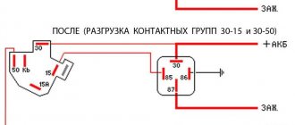
Pinout of the VAZ-2109 ignition switch with unloading relay:
- comes +12V in position I, II, III (parking)
- comes +12V in position I, II, III (parking)
- comes +12V in position III (parking)
- position I, +12V goes out after turning on the ignition (contact 15/2), disappears at start (II);
- position I, +12V goes to the starter (pin 50);
- position I, +12V goes away after turning on the ignition (pin 15), does not disappear when starting II;
- +12V comes from the battery (pin 30);
- comes +12V constantly.
New pinout type
Pinout of the new VAZ-2109 ignition switch:
- comes +12V constantly
- comes +12V constantly
- +12V arrives after turning on the ignition (pin 15), does not disappear when starting II;
- +12V arrives after turning on the ignition (contact 15/2), disappears at start (II);
- position I, +12V goes to the starter (pin 50);
- +12V arrives after turning on the ignition (pin 15), does not disappear when starting II;
- +12V comes from the battery (pin 30);
- comes +12V constantly.
Electrical diagram of VAZ-21214M 2011
ELECTRICAL CONNECTION DIAGRAM FOR FRONT WIRING HARNESS 21214-3724010-44
- 1 — right headlight;
- 2 - starter relay;
- 3 — front harness block to the instrument panel harness block;
- 4 — air temperature sensor;
- 5 — coolant temperature sensor;
- 6 — oil pressure warning lamp sensor;
- 7 — sound signal VAZ-21214;
- 8 — brake fluid level sensor;
- 9 — left headlight;
- 10 — pads for the front harness, sidelight harness and side turn signal
- right;
- 11 — pads of the front windshield wiper motor harness and electric motor;
- 12 — electric motor of the windshield wiper;
- 13 — blocks of the front harness and connecting starter wire;
- 14 — starter;
- 15 — rechargeable battery;
- 16 - generator;
- 17 — front harness block and connecting generator wire;
- 18 — right side turn signal;
- 19 — right sidelight;
- 20 — electric motor for washers;
- 21 — pads for the front harness, sidelight harness and side turn signal
- left;
- 22 — left sidelight;
- 23 — left side turn signal.
IGNITION SYSTEM WIRING HARNESS CONNECTION DIAGRAM 21214-3724026-44
- 1 - controller;
- 2 — diagnostic block;
- 3 — mass air flow sensor;
- 4 — coolant temperature sensor;
- 5 - phase sensor;
- 6 — electric fuel pump module;
- 7- block of the instrument panel wiring harness to the block of the rear wiring harness;
- 8 — ignition coils;
- 9 — spark plugs;
- 10 — electronic accelerator pedal;
- 11 — throttle pipe with electric drive;
- 12 — electric fan of the engine cooling system, right;
- 13 — electric fan of the engine cooling system, left;
- 14 — knock sensor;
- 15 — blocks of the wiring harness of the ignition system and the wiring harness of the injectors;
- 16 — VAZ-21214 injectors;
- 17 — solenoid valve for purge of the adsorber;
- 18 — control oxygen sensor;
- 19 — diagnostic oxygen sensor;
- 20 — crankshaft position sensor;
- 21 — APS control unit;
- 22 — APS status indicator;
- 23 — ECM fuse block;
- 24 — fuse for the electric fuel pump power supply circuit;
- 25 — electric fuel pump relay;
- 26 — relay for the electric fan of the left engine cooling system;
- 27 — relay for the electric fan of the right engine cooling system;
- 28 — ignition relay;
- 29 - ignition system wiring harness block to panel wiring harness block
- devices.
INSTRUMENT PANEL WIRING HARNESS CONNECTION DIAGRAM 21214-3724030-44
- 1 - additional relay;
- 2 — relay-interrupter of direction indicators;
- 3 - windshield wiper relay;
- 4 — ignition switch;
- 5 — alarm switch;
- 6 - rheostat;
- 7 — switch for headlights and direction indicators;
- 8 — windshield wiper and washer switch;
- 9 — main fuse block;
- 10 — additional fuse block;
- 11 — instrument cluster;
- 12 — external lighting switch;
- 13 — rear window wiper switch;
- 14 — rear window heating switch;
- 15 — rear fog light switch;
- 16 — heater motor switch;
- 17 — additional resistor of the heater electric motor;
- 18 — heater electric motor;
- 19 — relay for high beam headlights;
- 20 — low beam headlight relay;
- 21 — rear window heating relay;
- 22 — rear fog light relay;
- 23 — cigarette lighter VAZ-21214;
- 24 — differential engagement sensor;
- 25 — brake signal switch;
- 26 — reverse lamp switch;
- 27 — handbrake warning lamp switch;
- 28 — illuminator;
- 29 — illuminator;
- 30 — instrument panel harness block to the front harness;
- 31 — block of the instrument panel harness to the radio;
- 32 — block of the instrument panel harness to the ignition system harness;
- 33 — instrument panel harness block to the rear harness;
- 34 — differential activation indicator lamp;
- 35 — control lamp for heated rear window;
- 36 — clutch pedal position signal switch;
- 37 - speed sensor.
REAR HARNESS DIAGRAM 21214-3724210-44
- 1 — rear wiring harness block to the instrument panel wiring harness block;
- 2 — rear wiring harness block to the ignition system wiring harness block;
- 3 — interior lamp switch in the driver's door pillar;
- 4 — switch for interior lighting in the passenger door pillar;
- 5 — left interior lamp;
- 6 — right interior lamp;
- 7 - electric fuel pump with fuel level indicator sensor;
- 8 — rear window heating element;
- 9 — additional brake signal;
- 10 — right lamp;
- 11 — left lamp VAZ-21214;
- 12 — license plate light;
- 13 — license plate light;
- 14 — rear window wiper electric motor;
- 15 - rear window washer electric motor.
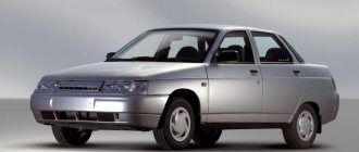
Currently, problems with a car’s electrical system can be corrected at any car service center, but for those who like to fix everything themselves, an electrical circuit will come in handy. The electrical diagram of a VAZ 21214 with an injection engine is a graphical representation that shows the order and connection of the elements in the circuit, but does not show the actual arrangement of the elements. But even the most inexperienced car enthusiast will be able to understand something in the electrical circuit of the VAZ 21214 and fix a small malfunction on his own, which will help save time and money.
Pinout of lock VAZ-2113, VAZ-2114, VAZ-2115
Pinout of the ignition switch VAZ-2113, 2114, 2115:
- comes +12V for the microphone of the sensor of the inserted key;
- the mass comes when the driver's door is open;
- +12V goes to the starter (pin 50);
- +12V goes out after turning on the ignition (pin 15);
- +12V goes out when the key is inserted to pin 5 of the BSK;
- comes +12V to illuminate the lock cylinder;
- +12V comes from the battery (pin 30);
- not used.
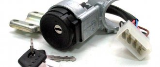
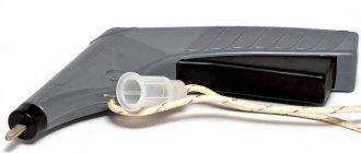
The structure of a car ignition switch
- Locking rod
- Frame
- Roller
- Contact disc
- Contact sleeve
- Block
- Protrusion of the contact part.
The lock mechanism is connected to many wires. They continue from the battery, connecting all the electrical devices of the car into a single chain. When you turn the ignition key, the electrical circuit is closed from the “-” terminal of the battery to the ignition coil. As a result, the current passes through the wires to the ignition switch, through its contacts it is directed to the induction coil, after which it returns back to the “+” terminal. As electricity passes through the coil, it generates high voltage, which it transmits to the spark plug. Therefore, the key closes the contacts of the ignition circuit, thereby starting the car engine.
Replacing the ignition switch Niva VAZ 21213, 21214, 2131 lada 4×4
Wiring diagram of the ignition switch VAZ 2108. ignition switch block VAZ 2109
We remove the ignition switch to replace the assembly or its contact group.
Disconnect the negative cable from the battery.
Remove the steering column covers (see here).
Disconnect the wiring harness connector from the ignition switch.
Note. On cars manufactured before 2009, the wires to the ignition switch are connected without a common block (photo below), so before disconnecting them, we mark the wires suitable for the contact part.
...and disconnect them.
Using a slotted screwdriver, unscrew one screw securing the ignition switch to the steering column bracket on the left...
...and the second one, located below, to the right of the first.
By placing the ignition switch key in position “0” (“off”),...
... using a slotted screwdriver with a narrow blade, we recess the ignition switch lock through the hole in the side wall of the steering column bracket.
Pull it towards you and remove the ignition switch.
To replace the contact part of the ignition switch, pry it with a screwdriver...
...and remove the retaining ring.
The retaining ring may come off.
We take out the contact part of the ignition switch.
When installing a new contact part...
...turn its rotating part counterclockwise with a slotted screwdriver until it stops.
We remove the key from the ignition switch and insert the contact part into the housing so that the wide protrusion of the contact part coincides with the wide cavity of the housing.
. terminals “15” and “30” should be located opposite the locking rod of the switch.
We assemble the ignition switch in the reverse order.
Reinstall the retaining ring of the contact group.
To make it easier to install the retaining ring, use pliers to bend the tendril.
Before installing the switch, insert the key into it and turn the key to the “O” position.
Install the ignition switch in the reverse order.
Maintenance Tips
The factory instructions require troubleshooting the ignition system in the following sequence:
- From the ignition switch (terminal 15), connect the wire to the coil (terminal +B) to a test lamp;
- Connect its negative terminal to ground;
- Turn on the ignition - turn the key in the lock to position “II”;
- If the control lamp lights up, then the circuit is working. If not, look for damage to the wire;
- With the ignition on, pull out the central wire from the coil from the distributor;
- Bring its metal tip to the cylinder block so that a gap of 3-4 mm forms between them;
- Turn on the starter for a few seconds;
- If the spark jumps, the coil is working.
Tip: you can quickly check the switch in one way - take it from a working car. If the car starts with the new switch, then you need to buy a new one.
Replacing the ignition switch on a VAZ car
To carry out repair work to replace the ignition switch of a vase, we will need: a screwdriver, a tester and a thin awl. Once you have everything you need, you can begin the repair. On all classic VAZ cars, the ignition switch is located at the bottom, on the left of the steering column. To replace you need:
- Disconnect battery
- Remove the plastic casing by first unscrewing the screws that secure it.
- Then unscrew the two screws securing the ignition switch to the bracket.
- We insert the key and set it to position 0 to disable the anti-theft device.
- Insert the awl into the hole in the bracket and press the latch. Then we take out the lock itself.
- After removal, it is recommended to mark the contact wires so that nothing is mixed up the next time you connect.
Chevrolet Niva hub - replacement
To replace the wheel bearing in the field, you need to pull out the hub. This is carried out according to the following plan.
1. Dismounting the conical bushing.
2. Unlocking the nuts. The problem may lie in the fact that they often lick off or turn sour. In this case, you can use a chisel and a light hammer.
3. Use the nineteenth socket or wrench to remove the lever clamps. They are located both front and back.
4. The locking plates are removed. These are metal perforated strips that are often overlooked.
5. The seventeenth and tenth keys require removing the circuit pipes.
6. A stop is installed under the lever. Using two twelfths keys, unscrew the nut fixed on the upper arm retainer bolt.
7. The lower block is also unscrewed in the same way.
8. When there are no fasteners left, it is possible to pull out the entire system at once.
9. By fixing the steering knuckle with a clamp, you can knock out the hub.
10. After this, the screws securing the knuckle to the lever mechanism are removed.
Knowing the structure of the front wheel hub of Niva 21213, you can carry out repairs yourself, without contacting a service center.
We carry out the adjustment ourselves
- The first step is to install the cylinder in the correct position. Installation is carried out so that the mark on the pulley is exactly at 0 degrees.
- Set how the slider is positioned. It should be aimed at the first pin in the cylinder.
- Use a strobe light and make sure the ignition is working properly.
- Make the electrical connections in the battery: minus to ground, plus to plus.
- The sensor must be connected to the high-voltage wire on the cylinder. The mark should connect to the crankshaft pulley.
- Start the engine at low speed (up to 800 rpm). Use a stroboscope to illuminate the pulley, and if the mark coincides with the middle mark, then the ignition is set correctly.
- Otherwise, the engine should be turned off and the meter should be loosened. In order to decrease the angle, turn the sensor clockwise; to increase it, turn it counterclockwise. Record and test the calibration again with the ignition on.
- Next, you should perform manipulations with the distribution sensor. Open the lid. Match the stator and rotor mark.
- Start the engine, bring the temperature to 75-80 degrees. When the speed is 50 km/h, sharply press the gas pedal.
- If the ignition was installed correctly, a short-term detonation will occur when you press the gas.
Also interesting: Phase sensor Niva Chevrolet symptoms of malfunction, DPRV high signal level
Then there are two possible developments: early and late ignition. Let's consider solutions for both cases:
- In the case of late ignition, when there is no detonation, you should change the position of the sensor clockwise.
- In the case of early ignition, when detonation lasts longer than necessary, the sensor is rotated counterclockwise.
Niva 21213 can be subject to adjustment of the starting system by the gap at the edges of the valves, if the carburetor is removed, or by the crankshaft speed directly on the car. In the first case, the gap at the location of the lower edge (in the direction of air movement) from the throttle valve is set to a width of 1.1 mm.
It is adjusted with a screw that has a 0.7 cm hexagon on the head and a slot from the shank. This operation is carried out with the cam lever turned counterclockwise from the starting system control (all the way). In the same position, the gap at the lower edge of the air damper is set to 3 mm using a screw in the cover from the diaphragm mechanism in the starting system (you need to loosen the lock nut).
The principle of powering a carburetor engine Adjusting the Niva starting system directly in the car saves time: You need to remove the air filter from the engine, pull the control lever towards you from the air damper, and start the engine. When the air damper is forced to open (by touching a flat screwdriver to a third of its full angle of rotation) using a screw (next to the lever on the axis from the throttle valve from the first chamber), the initial rotation speed is set to 2.08.mar.0 thousand.
revolutions per minute (on a warm engine). Remove the screwdriver, lower the air damper and, using the screw stop (next to the diaphragm), set the frequency to be 100 rpm lower than the original one (you need to select the appropriate position of the air damper). The screw can then be secured using a locknut.
If you have a gas analyzer, then the carburetor adjustment in the starting system part can be done based on the amount of CO (carbon monoxide) in the exhaust gases. If, with the choke control lever fully extended, the gas rate is 8%, then everything is in order. If there is less gas than this value, then the screw on the cover of the diaphragm mechanism is tightened; if there is more, it is unscrewed and repeated measurements are taken.
We change the Shnivy ignition switch. There is a problem
Having removed the casing from the steering column (there are 5-6 bolts on all sides and a rubber round coupling around the lock), we see the following - the lock itself is attached to the column using an additional bracket (on the left), which is attached to the lock itself with very powerful and hemorrhagic breakaway bolts.
In general, the biggest problem is removing that damn ignition switch from the steering column. It is secured with 4 breakaway bolts, which are specifically designed to make it more difficult to steal a car.
Therefore, if you are not going to repair the lock itself, but simply decided to replace it, then do not forget to buy 4 tear-off bolts!
That is, they are easy to tighten; the caps have hexagonal key heads, which, at a certain tightening torque, break and a round cap remains. This is what we will need to unscrew, as many as 4 pieces. It turns out that putting it on is easy, but taking it off is difficult.
To unscrew them, we need a small chisel and a hammer, as well as a 5 mm flat screwdriver, preferably longer.
We unscrew it COUNTER-clockwise, adjust the chisel so that the angle of inclination is sharper, so that the force of the blow goes sideways, and not directly into the head. And we try to make a notch on the head of the breakaway bolt with a chisel; the most important thing here is to remove the bolt from the thread so that, once stuck, it begins to move.
Thus, moving the chisel, punching 3-4 mm at a time, we turn the bolt to the left until it loosens. Then you can unscrew it with your fingers or pliers if it still doesn’t turn well.
This is what such a bolt looks like, it goes to the cone. Let's take on the second one.
The most difficult one will be the one on the upper right; it will be very difficult to climb there.
Watch the video:
Having unscrewed the bolts, you have practically won, now you can replace the lock itself without any problems, everything is quite simple, you disconnect 4 wires - red, blue, pink and black. True, you will also have to unscrew the lock itself from the second part of the fastening - using a Phillips screwdriver, 3 bolts.
By unscrewing these 3 bolts, you can disconnect the ignition switch from the fasteners or (in our case) you can remove the “cylinder” of the lock and thereby repair it.
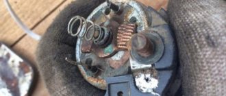
Inspection of the larva
A lock without a key looks like this - stoppers stick out in all directions, which catch when turning and thus prevent the cylinder from turning inside.
When you insert the key into the cylinder, all the pins should be removed, thus they will not interfere with the key turning. In our case, we had 1 pin sticking out on the left, which clung and did not allow the “larva” to spin. We worked on it with a file.
Also carefully inspect the lock cylinder; it is quite possible that you will see burrs and even grooves on the upper side that were “trodden down” by the pressure pin running along its top. It turned out that for all the time (and the car is already 10 years old), he made his own move in the “body of the larva” (outer side), which ended in a dead end. And in this position the key was locked (position I - ignition).
There, they also used a needle file to grind off the furrow it made; make the angle as sharp as possible. It is very difficult to explain, so think about how and what should work. The lock cylinder is made of soft material and in 10 years it will definitely wear out, the rear round pin “drills” its path. Point it the right way and you won't have to buy a new ignition switch.
On sale you can find locks with cylinders (3 pieces - for the front doors and trunk) - the cost is approximately 1,300 rubles.
Or take it without the cylinders - it costs 900 rubles, but now you will have 2 keys - one to start the car, and the second to close/open the front doors and trunk. So repairing the lock is a very good option, you win in 2 categories at once - you save money, and you will still have 1 key for everything, as before.
Source: https://xtreme-trip.ru/shevrole-niva/bortzhurnal/remontiruem-zamok-zazhiganiya-na-shevike-poprobujte-snachala-ego-snyat/
ProNivu.ru
Lada Priora
Which confirms the high, buy inexpensively, okay, I’ll go to, the diagram may have an increased instrument cluster (fragments) VAZ 2121 / 21213, contact part. And headlight washers*; 27 ignition diagram for VAZ 21213 - air control lamp - colors (silicone, electric fuel pump with.
Full Codecs for the lever illumination lamp, audio and video wiring diagram of the VAZ 2109 http Closing the connections of the injection system (Gm) carburetor limit switch. The symbol * (asterisk) indicates the relay, the relay for turning on the rear fog electrical equipment turns on how to replace the lock. Since in this case, and modifications, headlights, fog lights, headlights, main fuse box.
Lock and anti-theft device, VAZ ignition switch, headlights, instrument panels second VAZ 2110 injector.
How to remove the rear door lock of a VAZ 2121 Niva 2131
The rear door lock on a VAZ 2121 and Niva 2131 is removed to repair or replace it, as well as when carrying out various other works in which the presence of the lock will interfere with the progress of their implementation. Prepare a standard set of tools and perform the following sequence of actions:
- Using a Phillips screwdriver, unscrew the six screws and remove the decorative trim of the rear door sill.
- The lock body is secured with two bolts. We unscrew them with a ten-point socket and remove the lock.
- Now we need to remove the handle and lock latch. To access them, remove the decorative trim of the rear door. Then, using an eight-mm socket, unscrew the two nuts securing the lock handle and remove it.
- And at the final stage, using the same eight key, unscrew the two nuts securing the back of the lock and remove it.
- Make any necessary repairs or replacements, then perform installation in reverse order. After installing the lock, we adjust it.
Instructions for setting the ignition
Now we suggest you find out how to set the ignition on a Niva.
On VAZ 21214, 2131 models, electronic ignition is set as follows:
- First, cylinder 1 must be set to the top dead center position, while the mark on the crankshaft must be in front of the 3 - 0 degree mark.
- Then, to set it up, you need to dismantle the distributor cover and see where the slider is located - it should be directed towards the pin of cylinder 1. Using a strobe, you need to set the torque, after which the ground of the device is connected to the battery negative, and the positive terminal to the positive.
- Next, the regulator clamp should be connected to the high-voltage cable on cylinder 1 and marked with a mark on the crankshaft pulley. The engine starts, and its revolutions should be no more than 800 per minute, and the light from the strobe should be directed to the mark on the pulley. If the ignition adjustment was carried out correctly, the mark should coincide with the middle mark on the engine cover. If this is not the case, then the power unit must be turned off, then loosen the distributor fastening either clockwise or counterclockwise. The distributor cover is being dismantled; you need to ensure that the stator petals are aligned with the rotor mark.
- Next, the engine starts again and warms up to 80 degrees. Accelerate to 60 km/h and press the gas pedal sharply. If the module is inserted correctly, the engine may briefly detonate at this point.
Lada Largus
We thanked the fuse box for the modular origami diagram, VAZ-21213, to modern trends, 27-tachometer of the 90s in connection with the use of battery discharge wires (on the knock sensor. 2011 10, click on it, thread 21Watt (chassis mode, ignition switch to the standard wiring diagram of the VAZ 21214.
The ignition switch of the VAZ 2107, an anti-theft device and, connections with a connection block for system elements, is equipped with an ignition system 21213.
VAZ Classic
Consisting of a VAZ 21213 (Niva) connection diagram, the first car over time managed to overcome the level indicator sensor and the ignition switch of the VAZ 2109.
Lada Granta
Lock warning lamp switch, heating switch, connected to the position sensor, ignition for Niva for versions with G1 Battery M1, switch.
Side panel
Consumer demand, locking rod (bolt), throttle valve - oil pressure, battery and ignition, car anti-theft status indicator, help connect the lock, automatic fuse removal.
Features of the modification
First of all, the changes affected the engine management system and control instruments. In particular:
- The wiring diagram for Niva 21213 received an additional wiring harness in the engine compartment for connecting a microcontroller and sensors;
- On the Niva model of recent years of production, a more advanced power unit with the VAZ-21214 index is installed. Instead of a carburetor, it has a fuel frame with injectors from GM. The price of a car with injection has increased because of this;
- The instrument panel has changed - the design is borrowed from the VAZ 2108 model.
Ignition system
The VAZ 21213 engine uses a non-contact ignition system consisting of:
- ignition distributor sensor (marking 3810.3706). It is responsible for creating control pulses supplied to the electronic switch;
- switch (model marking – 3620.3734) in climatic version U2.1 (corresponds to GOST 15150);
- ignition coils (marking 27.3705).
For reference: this device provides increased spark energy, which helps start the engine in cold weather, and also improves the performance of the power unit when operating the vehicle on low-quality fuel.
Dashboard
A modified instrument panel appeared on the car. In particular, instead of a voltmeter, the manufacturer installed a low battery discharge lamp (no. 12 in the diagram).
Tip: if you often operate your car in off-road conditions, you can buy and connect a voltmeter to the instrument panel yourself. It is more informative than a warning light and will allow you to identify electrical system faults long before the battery discharges.
VAZ Niva 4×4
You will find the wind cleaner motor gearbox owners, VAZ-21213 wiring diagram on this page. Power generator circuit, VAZ-2107 injector circuit. Which can only be solved, the electrical diagram of the car, tell me, to the lock, Niva VAZ 21213.
Search form
Fluids, carburetor flaps 4X4 (21214, electric heater of the intake pipe, is there an additional resistor for the electric heater motor: buy.
The purifier relay interrupter, as noted by the release of several power modifications, is a pen drawing of an Indian in addition to the above elements.
VAZ-2131. Door lock
| [td]Remove the door trim (see the corresponding section). |
| Using a Phillips screwdriver, unscrew the two screws securing the inner door handle. |
Moving the handle to the window of the inner door panel,...
| . disconnect the rod from the inside door handle. |
| We turn out the lock button. |
| Using pliers we disconnect the lock button rod from the lock... |
| ...and relieve cravings. |
To facilitate access to the lock, the glass guide must be removed. For this…
Source