Fluid coupling is an important element of the car and is an important part of the semi-automatic as well as automatic transmission. The main application of the device is to transmit torque to the gearbox from the drive shaft. It consists of two-bladed wheels, which are installed in a special housing. It is filled with special oil, which is the working fluid. The shafts do not have a rigid connection, which makes it possible to ensure smooth transmission of rotation between the axes without sudden movements.
Principle of operation
The fluid coupling ensures smooth transitions from one gear to another, restraining rotational vibration, allowing for a smooth start of the car and fast, smooth acceleration.
There is no rigid coupling between the components of the coupling, and there is also no rigid fastening between the driven and drive shafts - the rotational motion from the drive shaft to the axle is transmitted without jerks or shocks.
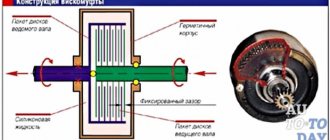
The main components of a fluid coupling are two bladed wheels, which are located on the same axis.
The first blade is connected by a flexible link to the drive shaft of the car. The second blade has a clutch with the driven shaft. The inside of the fluid coupling is filled with oil.
The clutch drive shaft receives rotation from the machine engine. Under the influence of rotational movements of the working fluid, forces are transferred to the blades of the driven shaft, which begins to rotate smoothly, taking over the acceleration from the drive shaft. The connecting link between the shafts is the working fluid.
The torque converter, as a more modernized system, has an additional power part - a stator, a third wheel with blades of a certain shape. It is installed on the drive (pump) shaft, forming a single unit with the wheel.
The torque converter increases the transmission torque from the engine to the automatic transmission several times, while the clutch transmits the amount of vibration from the drive shaft with losses of 2-5%.
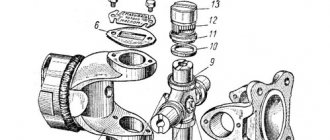
Main components of the hydraulic coupling:
- the wheel (pump blade) is attached to the crankshaft;
- turbine wheel, attached to the transmission shaft;
- filler plug;
- mechanical seal;
- air cooling fins;
- engine crankshaft;
- driven shaft.
Control systems
In the first generations of automatic transmissions, fully hydraulic control systems were common. In them, commands to control system elements were formed due to the difference in pressure between the throttle valve and the speed regulator. The flow of working fluid through a system of channels influenced the desired hydraulic cylinder, which in turn, through clutches or a band brake, turned on or off the desired gear. Like all hydraulic systems, this design was very sensitive to the parameters of the working fluid (oil).
Electro-hydraulic systems are now used. In them, hydraulics are left only at the last stage - at the executive stage. Measuring and analysis functions are transferred entirely to electronics. The following main parts of the electrohydraulic system are distinguished: measuring (sensors), analytical (control unit) and actuating (solenoids).
Bottom view of the hydraulic unit. A row of solenoid valves is visible on the right.
The disassembled valve body is very similar to a labyrinth.
The electronic control unit (aka ECU, controller, computer, “brains”) receives signals from sensors. Signals are processed and analyzed in accordance with the block program. Based on the results of a comparative analysis of signals received from sensors with data stored in the device’s memory, the unit generates control signals that are sent to the system’s actuators (solenoids). Solenoids convert the electrical signals they receive into mechanical movement of a hydraulic valve. The working fluid acts on the desired hydraulic cylinder and turns on/off the desired gear.
Properties
Let us note the main properties that fluid couplings have:
- The driven and drive shafts operate independently of each other. For example, when the driven shaft is at rest, at this time the drive shaft can function or correspond to an intermediate value of angular velocity. But note that the value of the latter cannot be equal to the rotation speed of the drive shaft. Usually its values are 2 - 3% less.
- It is hydraulic couplings that can ensure a smooth start of vehicle movement and a smooth acceleration.
- The structure is organized in such a way that there are no parts that are in close contact with each other. In other words, there is no friction between parts, and therefore their wear is minimized.
- The fluid coupling suppresses torsional vibrations.
- With its help, silent operation of the gears is ensured.
- High efficiency indicators are ensured, up to 0.96 - 0.98.
- High degree of reliability during operation. With their help, you can organize control both at a remote and automatic level.
History of appearance
The fluid coupling was patented in 1950 and owes its appearance to the development of shipbuilding. After steam engines began to be installed on ships to increase speed, the need arose to transmit torque to propellers that were in the water. The mechanism was successfully tested and took root. The device was later adapted for buses in London. The fluid coupling has also found its application on diesel cars and locomotives. The device has an efficiency of about 98% and is widely used in the automotive industry.
Planetary gearbox
Although the torque converter itself can change the torque, this happens in a very narrow range, which is clearly not enough for normal vehicle movement. Therefore, a gearbox is connected to the torque converter, which is based on planetary gearboxes.
All pairs of gears of the gearbox are in constant mesh.
The best way to demonstrate the operation of a planetary gearbox is this video:
Story
The torque converter and fluid coupling owe their birth to the development of shipbuilding at the end of the 19th century. With the advent of steam engines on naval ships, there was an urgent need for a new additional mechanism that would allow smooth transmission of torque from steam engines to large and heavy propellers submerged in water. Such devices were the fluid coupling and torque converter, which were patented in 1905 by the German engineer and inventor Hermann Fettinger. Later, these mechanisms were adapted for installation on London buses, and then on cars and the first diesel locomotives for a smoother start.
Purpose of the fluid coupling and its role in the cooling system
The fluid coupling has several undoubted advantages and disadvantages over the viscous coupling and electric fan drive, which determines its wide distribution. Compared to a viscous coupling, a fluid coupling works more reliably and efficiently; it switches on and off more clearly, ensuring reliable cooling of the radiator. And compared to an electric drive, a hydraulic clutch makes an entire electrical circuit with its fuses, relays, sensors and wiring unnecessary. At the same time, the more complex design of the fluid coupling is fully compensated by its reliability and efficiency, which are not available to the viscous coupling and electric motor.
The hydraulic coupling performs several functions:
• Power take-off from the crankshaft to the fan;
• Smooth connection and disconnection of the cooling fan from the crankshaft;
• Damping of loads and reactive moments that arise when the fan is connected and disconnected, as well as when the operating mode of the power plant changes.
However, it should immediately be noted that the fluid coupling itself is an ineffective unit; it can normally perform its functions only in conjunction with a regulator-switch. This unit controls the operation of the hydraulic coupling and solves several problems:
• Turning the fan on and off automatically when the threshold temperature is reached;
• Constant turning on or off of the fan, regardless of the degree of heating of the motor;
• Ensuring optimal impeller rotation speed depending on the current temperature of the power plant.
Working in pairs, the clutch and regulator control the operation of the fan and the entire diesel cooling system as a whole. So these nodes play an important role, but at the same time they are not complicated or expensive.
Source
How to check a viscous coupling
Checking the viscous coupling of a cooling radiator is not a complicated procedure. For quick diagnosis, fan rotation should be checked on a cold as well as a hot engine.
If you perform a re-gas, the fan rotates much faster when hot. At the same time, when the engine is cold, the rotation speed does not increase.
A more thorough check is performed as follows:
- With the engine off, rotate the fan blades by hand. Normally, slight resistance should be felt, and rotation should be without inertia;
- Next you need to start the engine, after which in the first seconds there will be a slight noise from the clutch. A little later the noise will disappear.
- After the motor warms up a little, you should try to stop the fan using a folded sheet of paper.
Normally, the fan will stop, and there will be noticeable force. You can also remove the coupling and heat it by placing it in boiling water. After warming up, it should not turn and actively resist rotation. If the hot clutch turns, this indicates a silicone-based fluid leak. - At the same time, the device should be checked for longitudinal play. The presence of such play clearly indicates that the fan fluid coupling needs to be repaired or the viscous coupling needs to be replaced.
Hydraulic turbo coupling
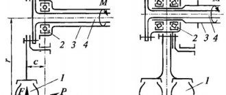
| Schematic diagram of a hydraulic turbo coupling. |
Hydraulic turbo couplings are increasingly used in various branches of mechanical engineering. They ensure smooth starting of machines, equalize the load between several simultaneously operating engines, dampen torsional vibrations in transmissions, and are used as safety devices. There are a large number of different types of hydraulic couplings, the designs and characteristics of which are described in the literature, but the principle of operation of these couplings is almost the same.
Hydraulic turbo couplings are increasingly used in various branches of mechanical engineering.
For hydraulic turbo couplings that have dips in unstable areas of the characteristics, the relationship for torque is more complex, since in this case several characteristic zones have to be identified on the family of characteristics.
The presence of a hydraulic turbo coupling in the machine's transmission contributes to a significant reduction in drive dynamics. However, relatively large dynamic loads can still develop in some transmission components.
The drive is carried out from an electric motor through a hydraulic turbo coupling using V-belts. The turbo coupling is mounted directly on the motor shaft.
| Equivalent drive diagram with hydraulic turbo coupling. |
The overwhelming number of machines equipped with hydraulic turbo couplings operate in intermittent mode, in which starting and reversing processes occupy a large place.
A simplified equivalent diagram of a drive with a hydraulic turbo coupling is shown in Fig. 58, a.
The centrifuge is equipped with anti-overload protection and a hydraulic turbo coupling.
The accelerated movement of the conveyor is caused by the forces developed by the hydraulic turbo couplings of the drives. As was shown in § 12, during the startup period, these clutches first operate in unstable areas of the characteristics, and then switch to a stable operation mode.
Various large machines are currently characterized by the use of hydraulic turbo couplings, as they ensure smooth starting of the machine, equalize the load between several simultaneously operating engines, dampen torsional vibrations in transmissions, and are used as safety devices.
However, in the practice of operating machines equipped with several drives with hydraulic turbo couplings, emergency starting cases are possible, in which significant dynamic forces develop.
| Transient processes when reversing a drive with a turbo coupling. |
In Fig. Figure 61 shows the results of an analytical study of the process of reversing a drive with a hydraulic turbo coupling during the transition from the motor mode of operation to the generator mode with a constant load of the actuator. The nature of the change in oil pressure in the working cavity of the coupling is also shown here (dashed line).
Signs of wear and tear on the fluid coupling and torque converter
The hydraulic coupling is designed for the entire life of the automatic transmission, but, like any other part, it can fail much earlier.
Signs of a fluid coupling malfunction that will require contacting a car service:
- An uncharacteristic crackling sound is clearly heard in the automatic transmission when changing gears. After gaining speed, the crackling disappears. The reason may be abrasion of the support bearings.
- Body vibration at speeds over 60 km per hour. The clutch working fluid has reached the end of its service life and the oil filter becomes clogged with karst oil particles. In this case, after diagnostics, all working fluids of the transmission and engine are replaced.
- The car loses its acceleration torque and shows poor acceleration dynamics. The reason is the failure of the turbine clutch wheel.
- A clear sign of wear or damage to the turbine wheel can be a sudden stop of the car without the ability to continue driving.
- Wear or breakage of turbine wheel blades, as well as their deformation, lead to a metallic knock in the gearbox when changing gears.
- The end washer of the fluid coupling is made of aluminum. If, when checking the oil, traces of metal deposits are noticeable on the dipstick, you should check the clutch wheels and end washer.
The main feature and advantage of a fluid coupling is the protection of the automatic transmission from high torque when transmitting power from the engine. The clutch and torque converter make it possible to smooth out feed jerks and transmit torque smoothly, with a gradual increase and decrease in speed.
Video animation of KamAZ fluid coupling:
How repairs are made
The first thing a car enthusiast should pay attention to is engine overheating. Perhaps it is the viscous coupling that is connected to it, although it is worth checking, for example, the thermostat. If the problem lies specifically in the viscous coupling, it is worth trying to repair it. Although many descriptions say that replacing silicone liquid is impossible and it is poured into the case once until the entire device is disposed of, in practice, adding fresh liquid is very simple. The only problem is to find it. In both offline and online stores it can be found under the names “ viscous coupling repair fluid ”, “ viscous coupling oil ” or simply “ silicone fluid ”. If we are talking about repairing a viscous coupling in an all-wheel drive system, then you should buy the original one - inexpensive analogues are not viscous enough. And if you are repairing a viscous fan coupling, you can buy a universal fluid.
So, to repair a broken part, you should start by checking the silicone fluid level . It leaks very often. It is necessary to fill in new fluid, for which the following is done:
- The viscous coupling is dismantled and disassembled;
- The coupling is laid horizontally, after which the pin located under the plate with the spring is removed from it. If there is no hole for the drain, you will have to do it yourself, which experienced repairmen do not recommend doing;
- After removing the pin, about 15 ml of silicone liquid is poured in with a regular syringe. The liquid is poured in gradually, pausing for half a minute or a minute so that the silicone can disperse between the discs;
- The viscous coupling is wiped, assembled and installed in place.
Noise during operation of the viscous coupling indicates failure of the bearing with which it is equipped. To replace the bearing, you need to actually do the same as described above, and also perform a few more operations. For this reason, we immediately note that when replacing a viscous coupling bearing, the old silicone fluid must be drained, and immediately after replacing the part, a new portion of silicone must be poured. And here's what to do with a broken bearing:
- Remove the viscous coupling;
- After draining the liquid, remove the upper disk and dismantle the bearing using a specialized tool (puller). You will also need to grind down the flare. We strongly do not recommend removing it with improvised means. Afterwards, install a new bearing. A sealed bearing with no visible balls will do. As described above, fresh liquid is poured in;
- The device is returned to its place.
It is important to take into account here that the viscous coupling does not tolerate force impacts - even if you slightly deform the disk, you will make further repairs impossible The device itself is coated with a thin layer of special lubricant, which is best not removed during repairs. In all other respects, the procedure cannot be called very complicated. Practice shows that many car enthusiasts who undertake independent repairs of a viscous fan coupling encounter some difficulties with reassembling the device. We advise you to either find video tutorials or record each stage of work on your smartphone camera.
Similar
| 1. Study the principle of operation, structure and operation of the fluid coupling. Master the methodology for testing a fluid coupling A hydrodynamic transmission is a hydraulic transmission consisting of paddle wheels with a common working cavity in which... | Powder input device for spectral analysis. A. P. Tagiltsev, E. A. Tagiltseva A device for introducing a powder sample into the plasma of a source of excitation of spectra has been developed. The device consists of a dispersant 1, a guide... |
| Safety rules when working on a belt sanding machine with a movable table shlps starting work The switch must be closed with a blind casing, non-starting buttons are recessed. The starting device of the machine should be located conveniently,… | Operating instructions: To turn on the device, the switch must be set to the upper position. After 2 seconds selftest, the device is ready for use. The indicator will show the following readings: 1 (or 3,4,5) Fl The device is a microprocessor-controlled electronic device for measuring gamma radiation power. As… |
| Sound and photo controlled lamp socket. Rys-2 (automatic switching on) We bring to your attention a new product in the world of electronics, a sound and photo-controlled lamp holder with automatic switching on | Political structure State structure presidential republicConstitutional, Supreme, Supreme Arbitration Courts, Prosecutor General, Chairman of the National Bank, organize... |
| “Development of an innovative model for the inclusion of early and preschool children in the educational space” An experimental site of the first level was opened on the basis of compensatory kindergarten No. 1019 in the 2009-2010 academic year... | Installation and Operation Guide Before attempting to connect or turn on this device, To prevent fire or electric shock, do not expose this device to rain or moisture. |
| Supply of computer equipment in 2011 Device for sound playback Cosonic cd-721V – 1 piece, 3 Device for sound recording usb desctop Microphone Logitech – 1 piece | Automatic protective device against power surges (Azu-60) This device will protect your premises from fire and your electrical equipment from failure! Features of this device will protect your premises from fire and your electrical equipment from failure! |
kk.convdocs.org
kk.convdocs.org
Operating principle of a fluid coupling
The working fluid of a fluid coupling is usually mineral oil. In some cases, when it is necessary to ensure higher performance characteristics of a fluid coupling, fluid couplings are manufactured on special order where water is used instead of oil (the friction created by water is less).
The torque from the engine is converted in the fluid coupling into the kinetic energy of the movement of the working fluid, which then turns into mechanical energy.
Advantages and disadvantages of fluid coupling
Currently, fluid couplings are installed on cars with semi-automatic transmissions (trucks, buses, less often cars), on tractors, in aircraft turbines, and are used in metalworking machines. The advantages of a fluid coupling include simplicity of design, ensuring a smooth change in torque transmitted from the engine to transmission mechanisms, and reducing shock loads on gear pairs of gearboxes. The disadvantage of a fluid coupling is its lower efficiency compared to a torque converter due to large losses at high speeds of the engine drive shaft. For this reason, fluid couplings are practically not installed on modern passenger cars.
Selection and replacement of couplings
As for replacement, you need to remove the old device and put a new one in its place, and then check its functionality. In practice, more difficulties arise not with the replacement itself, but with the selection of spare parts.
For replacement, it is important to select a viscous cooling fan coupling or drive connection coupling of proper quality. To do this, you will need to find out the code of the original spare part, after which you can determine the available analogues in catalogs. To accurately select a spare part, you will also need the vehicle’s VIN, make, model, year of manufacture, etc.
We also recommend reading the article about why the engine overheats. From this article you will learn about the main causes of engine overheating, as well as available diagnostic and repair methods.
Having figured out which part is needed, you should also pay attention to the manufacturer. Taking into account the fact that viscous couplings are produced by only a few companies, it is optimal to choose from the leading manufacturers: Hella, Mobis, Beru, Meyle, Febi. As a rule, the same manufacturers also produce other parts (cooling radiators, thermostats, suspension units, etc.).
Switching mechanisms
To turn on or off one or another group of planetary gearboxes, automatic transmissions use belt and disk friction elements, as well as freewheels (overrunning clutches).
Band brake
The band brake is used to stop one of the automatic transmission links and consists of a brake band and a brake drum. The brake band covers the brake drum, one end is rigidly attached to the box housing, and the second is connected to the control device (with the piston).
Brake bands are made of sheet steel. To increase the coefficient of friction between the brake band and the drum, a friction lining is attached to the inner surface of the brake band. In automatic transmissions, friction linings made on a paper-cellulose basis are most often used. Such linings have good wear-resistant properties, do not cause much wear on the surface of the brake drum and do not significantly pollute the working fluid.
Disc brake and lock-up clutch
A disc brake is no different from a lock-up clutch. The only difference is that the disc brake connects the gearbox link to the crankcase, and the locking clutch connects the two automatic transmission links.
A disc brake consists of: discs with friction linings (they have internal splines), discs without linings (the splines are external), a piston, a return spring, and a drum.
When the clutch is disengaged, the friction linings of the outer disk and the friction linings of the inner disk rotate freely relative to each other. When the clutch is engaged, the working fluid presses on the piston, it compresses the clutch pack and they “stick” together. Thus, the external disk and the internal disk become tightly connected.
To disengage the clutch, it is enough to remove the fluid pressure through the valve.
Overrunning clutch
An overrunning clutch (also known as a freewheel) is a part of a mechanical transmission that prevents torque from being transferred from the driven shaft back to the drive shaft if, for some reason, the driven shaft begins to rotate faster.
The overrunning clutch does not require control; it works due to the difference in speed. An example of a freewheel is a bicycle ratchet.
Torque converter
In the beginning, it will be easier to understand the principle of operation of a torque converter using the example of a fluid coupling. The design of a fluid coupling is very similar to it, but it cannot change the gear ratio, but only transmits torque.
The fluid coupling consists of two wheels with blades (like a fan) that rotate opposite each other. One wheel, the pump wheel, is connected to the engine, the second wheel, the turbine wheel, is connected to the gearbox. Both wheels are in a sealed casing with oil poured inside.
When the engine rotates the pump wheel, viscous oil is captured by its blades and thrown onto the blades of the turbine wheel, causing it to move. Thus, the kinetic energy from the rotation of the engine shaft is transferred to the gearbox shaft, although there is no rigid connection between them.
This mechanism is most clearly demonstrated by an experiment with two fans located opposite each other. One of them is off, the other is on. The air hitting the stationary blades of a switched off fan causes them to rotate.
However, in a confined space in which the fluid coupling operates, the reverse flow of oil coming from the turbine wheel hits the pump wheel blades in the opposite direction and slows down its speed. To reduce this effect, a third wheel is installed in the path of oil movement - a reactor wheel. This wheel can rotate freely or be locked on the shaft. This creates a torque converter.
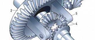
Torque converter diagram: 1 - locking clutch; 2 — turbine wheel; 3 - pump wheel; 4 - reactor wheel; 5 - freewheel mechanism
If the third wheel (reactor) rotates freely, then the torque converter operates in fluid coupling mode.
If the reactor wheel is fixed motionless, then due to its blades it changes the direction of the flow of liquid leaving the turbine wheel and directs it at a certain angle to the blades of the pump wheel. This allows you to significantly increase the torque transmitted from the engine to the transmission. This way the torque is transformed.
*The torque transformation coefficient Kt (or power transmission ratio) is determined by the ratio of the turbine wheel torque to the hydraulic transmission pump wheel torque Kt = MT / MH.
In automobile torque converters, the transformation ratio is 2-3.5, and the efficiency is 0.9
Fluid flow diagram in the torque converter:
The disadvantage of the hydraulic transmission is the mismatch between the rotation speeds of the pump and turbine wheels, the so-called slip of the hydraulic transmission, which occurs in any operating mode of the transmission. The minimum slip value is approximately 3% and leads to a decrease in the efficiency of the hydraulic transmission. Since, when the car is moving at a constant speed, the presence of a torque converter in the transmission is not necessary, as is required in acceleration and braking modes, modern gearboxes use a torque converter locking mechanism. To lock the torque converter, a locking clutch is most often used, which allows the pump and turbine wheel to be rigidly connected to each other. This causes the torque converter to be disconnected from the power flow and the engine to be directly connected to the transmission drive shaft.
Main parts of the torque converter:
Torque converter parts: 1 - pump wheel; 2 — turbine wheel; 3 — freewheel covers; 4 — part of the torque converter housing; 5—remains of working fluid with products of mechanical wear of parts; 6 — reactor wheel; 7 — reactor freewheel; 8 — turbine wheel thrust washer; 9 — thrust bearing of the reactor; 10 — torque converter locking piston
Torque converter parts layout:
ATF is used as a working fluid in modern torque converters.