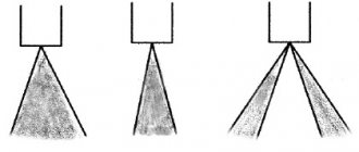
Electronic vehicle control systems are designed to monitor and control its various mechanical, hydraulic and pneumatic systems. The purpose of electronic control systems is to make the vehicle easier to control, increase control over the situation on the road, increase driving safety, and improve the traction characteristics of the car. An extensive knowledge base on electronic systems is available when purchasing licenses and voucher codes for the ELECTUDE distance learning system.
What is ECM, decoding
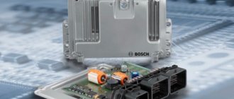
ECM is an electronic engine control system. It is a set of electronic computing equipment responsible for the operation of only the engine or the engine together with other systems of a passenger car. Essentially this is a car on-board computer.
Types of systems
ECMs are divided into two types, which have their own advantages and disadvantages:
- In the first case, which is often called by the English abbreviation ECM (Engine Control Module) , the computer controls only the motor.
- In the second, ECU (Electronic Control Unit) , it is responsible for all systems of the car: engine, suspension, etc.
IMPORTANT! A unit common to all systems is used more often, since it simplifies the internal structure of the car from a design point of view and reduces the cost of assembly. That is, it is easier to route all the wires from all sensors to one place than to install them in different places.
On the other hand, a single unit is a less secure option than “separate areas of responsibility” for different systems. Its malfunction will affect the operation of all machine mechanisms, while individual units operate independently of each other. For example, the braking system may operate correctly if there is a control or engine failure.
The single control unit consists of the following elements:
- Engine-transmission unit.
- Brake system control unit.
- Central control unit.
- Synchronization block.
- Body control unit.
- Suspension control unit.
With every change in model range, leading automakers set themselves the goal of attracting buyers with something special. Some offer a luxurious interior and rich equipment, others cultivate a sporty character and improve powerful dynamics, while others rely on more economical engines with alternative energy sources. However, in all cases, the future of the automotive industry is unthinkable without electronic control systems. The rapid development of technological “fillings” gives reason to believe that progress in the automotive industry has firmly defined its priority direction.
LANE ASSIST SYSTEM
This electronic assistant warns the driver of deviations from the selected lane and, if necessary, intervenes in the steering. The system is effective when driving on highways and developed roads, i.e. where there is high-quality marking.
The situation in front of the car is projected onto a light-sensitive matrix of a video camera located on the windshield and converted into a black and white image, which is analyzed by the electronic control unit. The system's operating algorithm recognizes road markings, calculates the vehicle's position on the lane and its trajectory. The driver is warned by vibration of the steering wheel, as well as visual sound and light signals. Corrective steering is carried out by an electromechanical power steering through an electric motor. To eliminate fogging or icing of the camera window, the heating element is automatically turned on. When deliberately changing lanes from one lane to another, the turn signal must be turned on, otherwise the system will impede the maneuver.
Well-known lane keeping assistants are: - Lane Assist - Audi, Volkswagen; — Lane Departure Warning System – BMW, Citroen, Kia, General Motors, Opel, Volvo; — Lane Departure Prevention – Infiniti; — Lane Keep Assist System – Honda, Fiat; — Lane Keeping Assist – Mercedes-Benz; — Lane Keeping Support System – Nissan; - Lane Monitoring System - Toyota.
AUTOMATIC PARKING SYSTEM
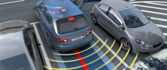
The trade name Parktronic System , due to its popularity, has become a common name for most passive parking systems installed on cars as an option. Let's take a closer look at the next generation of development of such systems - parking autopilot. For the first time, this dream of many car enthusiasts was embodied in the Volvo YCC concept.
The smart parking device uses ultrasonic sensors, similar to the passive system, but with a longer range. As a rule, 12 sensors are installed on a car: 4 in front, 4 in rear and 4 on the sides of the car. The side ones are designed to help you find a suitable parking space. When driving at a certain speed (about 30–40 km/h), they record the distance between parked cars, and in some systems, their position relative to your vehicle: parallel or perpendicular. A sufficient distance for parking is taken to be a distance exceeding the length of the vehicle by 0.8 or 1 m. The system is forced to be turned on if parking is necessary. The electronic control unit receives signals from ultrasonic sensors and converts them into control actions on the actuators of other vehicle systems: electric power steering, stability control and engine control systems, and automatic transmission. The vehicle can be parked by the driver using instructions provided by the system (recommendations for turning the steering wheel to a certain angle and direction of movement) or automatically. If in city traffic you need to park faster than your assistant does, the system can always be switched from automatic to manual mode. In the latest system designs, automatic parking can be performed while the driver is both in the car and outside it - with the key. Well-known intelligent parking assistance systems are: - Park Assist and Park Assist Vision - Volkswagen; — Intelligent Parking Assist System – Toyota, Lexus; — Remote Park Assist System – BMW; — Active Park Assist – Mercedes-Benz, Ford; — Advanced Park Assist – Opel.
ADAPTIVE CRUISE CONTROL SYSTEM
Adaptive cruise control designed to automatically control speed. Intelligent speed controllers allow you to estimate the distance to the vehicle and slow down if necessary to maintain the distance. Modern systems are “smart” enough to respond correctly to accelerations and lane changes of the car in front. Adaptive cruise control is indispensable in heavy traffic conditions. The system itself slows down and stops, and moves off itself as soon as such an opportunity arises (Stop&Go function).
The main structural elements of the ACC system are distance sensors (radars or lidars), which measure the speed and distance to the vehicle in front, and an electronic control unit, which, based on the analysis of input information from sensors and other systems, generates a control action to change the speed of movement. Adaptive cruise control does not have its own actuators, but uses other electronic systems of the car, which it communicates with through control units: stability control system, electrically driven throttle valve, automatic transmission. The system operates in a speed range from 30 to 180 km/h. Modern ACC systems support speed limits from 0 to 200 km/h, as well as braking and starting modes in heavy traffic conditions. To improve vehicle safety, some adaptive cruise control designs may include preventive safety, emergency braking and GPS navigation systems.
Well-known adaptive cruise control systems are: - Preview Distance Control - Mitsubishi; — Radar Cruise Control – Toyota; — Distronic (Distronic Plus) – Mercedes-Benz; — Active Cruise Control – BMW; — Adaptive Cruise Control – Volkswagen, Audi, Honda.
AUTOMATIC CONTROL SYSTEMS
The rapid development of automotive electronic systems makes the idea of an unmanned vehicle a reality. Driving skills are not required in such cars. The autopilot, which controls the dynamics of longitudinal and lateral movement, allows the driver to completely relinquish control of the car.
Today, many companies are actively working on creating an automatic vehicle control system. Audi, BMW, Cadillac, Ford, Mercedes-Benz, Nissan, Opel, Toyota, Volvo, Volkswagen already have parking autopilots and systems for automated movement in traffic jams or on highways. An integrated approach to creating an unmanned vehicle is being implemented by only two companies - Google Corporation, which has been working in this direction for several years, and the Russian company RoboCiVi. Google's self-driving system has already been tested on prototype vehicles in the United States. The project to create a Russian “drone” started in early 2012. The main unit of the system is the GLONASS navigation complex. Currently, it is being tested on a small-sized model, which implements the functions of routing, starting, maneuvering, and braking when an obstacle arises. Temporary Auto Pilot, TAP – Volkswagen The system allows the driver, under certain conditions, to give control of the car to automatic control. The new product, called “Temporary Autopilot,” became an intermediate step on the way to a robotic car. It combines well-known Volkswagen serial technologies into one whole: adaptive cruise control, assistants for monitoring road markings and signs. The system maintains a safe distance from the vehicle in front and, if necessary, brakes the vehicle to a complete stop. It regulates driving speed by reading road signs, monitors lane markings and automatically adjusts the steering wheel if the car unintentionally drifts out of its lane. The driver can always deactivate TAP and take over control. The new technology can be used not only when driving on the highway, but also in traffic jams. The temporary autopilot operates at speeds of up to 130 km/h and is already being implemented in production cars. Traffic Jam Assistant – Audi This is the first production autopilot system for driving in traffic jams. It automatically maintains a distance from the car in front, brakes, accelerates, turns, avoids obstacles and even gives way to emergency vehicles. Operates at speeds from 0 to 60 km/h. Traffic Jam Assist – Ford Automatic traffic jam assist system maintains the desired speed and ensures the vehicle moves in traffic. Serial use on cars is planned to begin in 2021. Traffic Assist – General Motors The system can control the vehicle at speeds up to 60 km/h. It recognizes not only turns and obstacles, but also road signs. ConnectedDrive Connect (CDC) – BMW A car equipped with the new product will be able to independently accelerate and brake, overtake and change lanes, drive from secondary roads to the main one, wedging at speed into the traffic on the highway. The CDC system is designed for automatic highway driving. The intelligent device, which implements the ideal driver algorithm, does not exceed the speed limit on the section, does not overtake on the right, and also returns the car to its lane after overtaking. Super Cruise – Cadillac The automatic control system ensures vehicle movement outside the city limits – on highways. It allows maneuvering, braking, and lane movement without driver intervention. SARTRE (Safe Road Trains for the Environment) – Volvo Allows several vehicles to travel along the road in an organized convoy. The cars line up at a distance of 6 m and completely repeat the movement of the leading truck, which allows drivers to rest, eat, and talk on the phone. If desired, each of the cars can leave the group at any time. Volvo is also introducing a new traffic jam driver that will appear in the Swedish brand's cars in 2014.
Where is the ECM located?
In the vast majority of cases, the ECM, or more precisely the ECU (electronic control unit), is located under the dashboard. In different car models, it may be located in the center or near the steering wheel. As a rule, it is quite easy to get to it using a regular screwdriver. This arrangement is made for ease of access. Visually, both domestic and foreign ECUs are a small (usually about the size of two palms) flat box with sockets for wires.
ECM device
Since the electronic engine management system is essentially a computer, it is technically designed in much the same way as a standard PC. The system remembers the basic settings laid down by the manufacturer and monitors compliance with these parameters during engine operation.
At a technical level, the block consists of:
- Read-only memory (PROM). This is the memory that contains the basic motor control algorithm. It can be changed manually. When the engine is turned off, the settings are not deleted.
- Random Access Memory (RAM). Memory that processes operational data coming from systems: compliance with the parameters specified in the PROM, errors, etc. The device has an additional power source - from a battery, so it can save data even if the power is interrupted.
- Electrically programmable memory device (EPROM). Memory where the anti-theft system codes are stored. Also responsible for the functioning of the immobilizer.
ELECTRONIC VEHICLE CONTROL UNITS
INTRODUCTION
Globalization and integration of the world economy have given rise to serious shifts in the international division of labor, in the territorial location of production, and the development of integration processes in transport. All this led to a significant increase in transportation by all modes of transport. The characteristic properties of vehicles, which are based on the technical and technological characteristics of vehicles, such as mobility, reliability, delivery of goods in small quantities over any distance, cross-country ability, which does not require significant costs for equipping travel routes, low capital intensity and quick return on capital investments, ultimately made motor vehicles the most popular and economically attractive in the transport sectors of the national economies of the world. The rapid growth of the world economy in the twentieth century, integration processes, international policies aimed at cooperation, as well as other reasons contributed to powerful progress in transport, both in quantitative and qualitative terms. The car is the most popular vehicle in the world. Millions of cars are produced every year. In order for each car to find its buyer, car companies are forced to constantly improve the design of the car. Modern models appear, new vehicle systems are developed and implemented. A car is a complex technical system consisting of many subsystems. A technical system is understood as a set of interconnected structural elements designed to solve a common technical problem. The main systems that determine the structure of a car are the engine, transmission, steering, braking system, supporting system, suspension and wheels. The design of a modern car is developing simultaneously in several directions: increasing safety. A car is an object of increased danger, which determines the development of various security systems. Active safety systems have become widespread, including anti-lock braking systems and exchange rate stability systems. The protection of the driver and passengers is significantly increased with the use of passive safety equipment; improved fuel efficiency. Fuel consumption largely depends on the design of the engine and gearbox. Engine efficiency is ensured by the use of a direct injection system, a Common Rail injection system. Fuel economy is also achieved by reducing the weight of the vehicle through the use of durable steels, light metals and plastics, and modern composite materials; increasing environmental safety. The car is a source of environmental pollution, which stimulates the continuous improvement of environmental safety. Modern Euro-5 environmental standards, which guide automakers, involve reducing harmful emissions and noise levels through changes in the exhaust system and the use of an engine management system; increasing comfort. This area covers a wide range of issues related to the desire of automakers to create cars that best meet the individual needs of consumers. Automatic transmissions, power steering, and climate control systems began to be used. The most advanced models are equipped with adaptive suspension and an active headlight system. Modern science about automotive on-board equipment and automatic control systems is developing in two directions: towards finding ways to improve the parameters and characteristics of existing devices, systems, apparatus and instruments; towards the development of new functional units, systems and blocks for the needs of automation and mechanization of work processes on a car. On the basis of scientific research, a radical improvement of classic electrical equipment has been implemented, and a number of on-board automatic control systems, completely unconventional for a car, have been created - electronic control units. This was made possible thanks to advances in semiconductor and microelectronic technology for manufacturing electrical circuits, which make up a significant part of automotive on-board equipment. Now cars are equipped not only with electrical contact blocks, but also with electronic control units. The design has changed and the efficiency of outdoor lighting equipment has increased. Along with the improvement of on-board devices, completely new electronic control units have been developed and widely used: engine; braking system; steering system; car security system; automatic transmission. Electronic control units, according to their functional purpose and the space they occupy, can be divided into comfortable (internal body equipment), mounted (engine equipment) and functional (body, chassis and chassis equipment). The first signs of the use of super-complex fourth-generation automatic control systems have appeared on the car. The ideas of using radar-computer and satellite car navigation systems and systems for determining coordinates on the ground have already been tested to simplify the automated movement of a car along city and highway roads, as well as to search for and locate vehicles in need of assistance. For a number of the world's largest cities, “electronic maps” have been compiled, which are recorded on laser discs. Using a disk drive, a computer and a color display, the driving route is automatically given to the driver. The system switches from reference marks on the ground. The fourth generation of on-board vehicle equipment, the main feature of which will be the complete computerization of control, regulation and monitoring processes, will also include such special systems as vehicle self-control in autopilot mode, vehicle self-protection from emergency situations, electronic backup of control functions and much, much more. A sign of classification by generation is the phased introduction of new technology: the first generation is the electrification of the car; creation of classic electrical equipment; second generation - introduction of analog semiconductor circuitry using discrete radio elements: creation of the simplest electronic circuits for controlling electrical devices; third generation - widespread introduction of digital electronic equipment on board the vehicle. Creation of new on-board automation systems, such as: electronic fuel injection, digital ignition control, electronic brake control, vehicle environmental systems, on-board self-diagnosis, circuit redundancy, etc.; fourth generation - complete computerization of automatic control, monitoring and regulation processes using a central on-board computer and with a significant expansion of the functions performed. Equipping a vehicle with radar equipment. Creation of completely new principles for driving a car and its components. An electronic control unit (ECU) can operate in either analog, discrete or digital mode, but it always “deals” with electrical signals. To coordinate signals and impacts of different energy natures, the ECU is equipped with converters of non-electrical impacts into electrical signals at the input, and inverse converters of electrical signals into non-electrical impacts (actuators) at the output. Input and output converters form the external periphery of the electronic control unit. The operation of electronic control units is based on physical processes and phenomena occurring in electric and magnetic fields and circuits. The purpose of this tutorial is to provide information in a concise and intelligible form about various electronic vehicle control systems, their diagnostics, show their structure and operation. When studying this discipline, students will have to comply with the requirements of the federal state educational standard of higher professional education in the training specialty 190109 “Land transport and technological means”, which provides for mastering the competence “mastery of the basic methods, methods and means of obtaining, storing, processing information, the availability skills in working with a computer as a means of information management” (PC-8). Chapter 1 Current in the electrical circuit Electronic vehicle engine control units Transistor ignition systems Electronic and microprocessor ignition systems Output stages with multi-terminal ignition coils Output stages with individual static distribution Output stage with controlled ignition transformer Electronic engine ignition control units Electronic engine control unit
Operating principle of the ECM
The main task of the system is the efficient operation of the engine. Based on the information received from various components, it regulates torque, power and other indicators depending on the operating mode of the engine, the configuration of the ECM and its type (the most popular are M20, M73, M74, M86).
Standard engine modes that the ECM distinguishes:
- Starting and warming up.
- Idling.
- Movement, braking.
- Changing gears.
The scheme of sources from which the ECM receives data depends on the car model and its configuration. Typically these are sensors: crankshaft position, phases, air flow, coolant temperature, throttle position, speed, oxygen and detonation.
In addition, the ECM constantly performs self-diagnosis, also based on sensor readings.
Electronic car control systems
Traffic safety enhancement systems consist of:
- anti-skid system, which prevents the wheels from slipping, which is especially important during sudden acceleration or driving uphill on a slippery road;
- anti-lock braking system, which prevents the wheels of a braking vehicle from locking and maintains its controllability and stability;
- a differential lock system, which increases the overall safety of the vehicle, improves its traction characteristics, facilitates the moment of starting and climbing, and ensures intense acceleration;
- a brake force distribution system that ensures effective traction of the rear wheels and prevents them from blocking and skidding;
- hill hold system and descent assist system;
- braking assistance system, it is activated in cases of emergency braking when the brake pedal is not pressed firmly but sharply. The principle of operation is to increase, if necessary, the pressure in the brake system;
- exchange rate stability system designed to maintain vehicle controllability and stability during maneuvers.
Watch a video about electronic car stabilization systems.
To ensure comfortable conditions, the cabin uses climate-controlled air conditioners, a voice control system, and a system for controlling outside air pollution and purifying it.
Diagnostics
In addition to automatically checking the correct functioning of the ECM, experts recommend regularly diagnosing the system. On average, maintenance should be done every 15 thousand kilometers. Diagnostics of the ECM is carried out using a special tester connected to a special connector. Sometimes a wireless adapter is used that uses a special protocol.
IMPORTANT! It is best if the indicators are deciphered by a specialist who, based on the data obtained, can draw a conclusion - which specific element of the ECM is acting up. After preliminary conclusions, a more precise check of the suspicious element is carried out.
Before carrying out tests using a scanner, you need to check the power supply of the system and its individual fragments. The cause of the malfunction may be damaged electrical wiring, short circuits, corrosion, or various interferences.
Malfunctions and their causes
Troubleshooting the ECM can begin after detecting a number of symptoms. First, when the ignition is turned on, all the system indicator lights should light up simultaneously, thus the system checks its diagnostic mechanism. After starting the engine, everything should go out at the same time. If any of them lights up while driving, this indicates problems in the internal combustion engine. At best, the system can shut down the engine to avoid serious damage. The list of negative situations in which the ECM malfunctions is long - the cooling system may become airless, the heater or thermostat may not work.
IMPORTANT! The ECM is a delicate system, so describing problems that can happen with the electronics can take a lot of time.
The main causes of malfunctions are:
- Failure of sensors sending data to the ECM.
- Failures in the control unit itself.
- Failures of the control system actuators (increase in resistance, break in the winding of the solenoid valve, etc.).
- Damage to electrical wiring.
- Intervention by outsiders in the design of electronic systems, which could result in a violation of their integrity.
Often the ECM breaks down due to mechanical damage. This may not necessarily be a shock; a strong vibration is enough to cause harm to the system. Next in terms of the percentage probability of damage to the ECM are: sudden temperature changes, corrosion, moisture ingress under the protective casing due to depressurization of the device. Also, the correct operation of the system is often disrupted due to incompetent interference in its functioning.
System repairs can only be trusted to specialists.
What electronic systems are installed in modern cars?
This article discusses the electronic components of cars, what they are and how they work.
ABS helps prevent wheel locking and skidding when braking
ABS (“ANTIBLOCK BRAKE SYSTEM”)
ABS – anti-lock braking system. This system allows you to avoid wheel locking during sudden braking or when braking on slippery roads. The control unit presses and releases the brake pads several times, as a result of which the wheels begin to rotate. ABS consists of: acceleration (speed) sensors installed on the wheel hubs; control valves that are installed in the brake system line; a control unit that receives signals from sensors and controls the operation of valves.
During braking, ABS continuously and accurately detects the rotation speeds of all wheels. If one or more wheels slow down faster than the vehicle's maximum calculated braking speed and, based on accelerometer readings, the ABS commands the modulator in the braking system to limit the braking force on the wheel(s). The braking force is restored after the wheel rotation returns to acceptable levels.
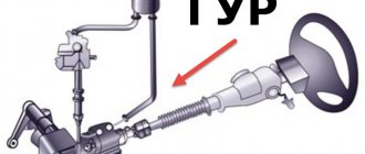
4WS (“4 WHEEL STEER”)
4WS – 4 steered wheels. Special steering mechanisms are built into the rear suspension, with the help of which the wheels turn. The control is carried out by a special electronic unit based on data on speed, angle of rotation of the steering wheel and wheels, etc., received from the vehicle’s sensors.
The system operates in two modes:
- At low speeds, the rear wheels turn in the opposite direction from the front wheels, and the steering wheel rotates at a smaller angle when performing the maneuver. That is, the steering sensitivity increases and the car becomes more maneuverable.
- At high speeds when changing lanes or quickly turning, the rear wheels turn in the same direction only at a small angle as the front wheels.
ACC (“ACTIVE CRUISE CONTROL”)
ACC – active cruise control. This system uses a three-beam radar to monitor the road ahead of the vehicle. If a vehicle ahead changes into your lane, ACC determines its direction and position and calculates an estimated speed based on the radar signal. The system modifies the vehicle's speed to maintain a safe distance between vehicles. Reducing speed is done by reducing the vehicle's traction or using the brakes. The safety distance value can be adjusted using the settings.
ACC (“ACTIVE COMING CONTROL”)
ACC is an automatic system for stabilizing the lateral position of the body in corners and variable suspension travel. May also be called ACE, CATS, CBC, BCS. ACC works together with ABS to prevent rear axle drift when cornering at high speeds. ACC work is based on the redistribution of loads between suspension elements. With a lateral tilt (roll), the rods move in different directions (one goes down, the other goes up). The middle part is twisted.
ACC stabilizes the position of the car when turning
ACC tries to lift the body from the inclined side and lower it from the opposite side. Thus, ACC ensures that the vehicle is aligned to the road plane. In addition to leveling, an increase in the adhesion properties of the car's wheels with the road when turning is also achieved.
AGS (“ADAPTIVE GETRIEBE-STEUERUNG”)
AGS is a self-adjusting automatic transmission system. AGS selects the optimal gear when the vehicle is moving. To determine driving style, the operation of the gas pedal is assessed. The slip limit and drive torque are monitored, as a result, one of the system programs (“normal”, “winter”, “mountain starting from a place”) is selected for selecting gears. In addition, AGS regulates unnecessary gear changes.
APC (“AUTOMATIC PERFORMANCE CONTROL”)
APC is a system that controls the engine (ignition, fuel mixture).
ASC (“ANTI-SLIP CONTROL”)
ASC – anti-slip system. Also called ASR, ASC+T, TCS, ETC, TRC, TRACS, STC. The main task that the system performs is to ensure vehicle stability when driving uphill or making a sudden start on a slippery surface. Stability can be ensured by redistributing torque to those wheels that, according to available data, have the best traction, and if this is not enough, then the supply of the fuel mixture to the engine is reduced, thereby reducing the power supplied to the wheels. The system is designed to operate at speeds less than 40 km/h.
A-TRC (“ACTIVE TRACTION CONTROL”)
A-TRC – active traction control system. This system is a more intelligent version of the usual one. A-TRC will not allow the car to slip in the most unfavorable conditions.
A-TRC prevents wheel slip
A-TRC automatically detects slipping of the drive wheel, brakes the wheel and reduces the torque transmitted to it, distributing it to other wheels. As a result, optimal torque is supplied to the drive wheel. A-TRC almost completely replaces differential locks in the most difficult conditions, while braking the wheels is not as strong when turning sharply. A-TRC together with VSC provide excellent vehicle handling on slippery roads.
AUC
AUC – outdoor air pollution control system. If the system detects a high content of harmful substances in the air, it automatically switches the air conditioner to recirculation mode.
BA (“BRAKE ASSIST”)
BA – electronic pressure control system in the hydraulic brake system. Also called PABS, PA, BAS. BA independently increases the pressure in the brake system when sudden braking is necessary or insufficient pedal force is applied.
VA helps with emergency braking
Moreover, the increase in pressure occurs much faster than a person could do. Emergency braking is recognized by the speed at which the pedal is pressed and the pressure on the pedal
D-4
D-4 – direct fuel injection technology. The fuel is supplied directly into the combustion chamber under high pressure. Thanks to this technology, engine performance characteristics are significantly increased. Fuel consumption is reduced and the level of harmful substances in gas is reduced.
DAC (“DOWNHILL ACESS CONTROL”)
DAC – hill descent assist system. When driving on steep slopes, if the DAC system detects that the wheel speed is less than the vehicle speed, it automatically changes the braking force on different wheels.
DAS assists during descent
DAC maintains a speed of around 5-7km/h, which is ideal on steep descents, and 3-5km/h when reversing on steep descents.
DBC (“DYNAMIC BRAKE CONTROL”)
DBC – dynamic braking control system. DBC is an addition to DSC (Dynamic Stability Control). Approximately 90% of drivers are unable to perform emergency braking in time. Despite pressing the brake pedal sharply, the pressure on the pedal is insufficient and a subsequent increase in pressure increases the braking power slightly. As a result, the braking power is not fully used.
The DBS system allows you to accelerate and intensify the build-up of pressure in the brake system during emergency braking and provides a minimum braking distance even when the brake pedal is lightly pressed. The determining quantities are the following: the rate of increase in pressure and the force applied to the pedal. The DBS system does not operate on the vacuum principle, but on the principle of hydraulic amplification. During emergency braking, such a system provides the best and most accurate dosage of braking force.
DDE (“Diesel Digital Elekronik”)
DDE is an electronic digital diesel engine management system. DDE regulates the injection start point, the amount of fuel supplied and the boost pressure, which ensures the most optimal compliance of these parameters in all engine operating modes, even in extreme conditions.
DDE improves diesel engine performance
The car becomes more economical (fuel consumption), high-torque (engine operation is smooth) and more environmentally friendly (toxicity in exhaust gases decreases). Monitoring the force of pressing the gas pedal and its position allows you to more accurately calculate the time, quantity, and pressure of fuel injection, which adapts the engine operating mode to different conditions and driving style.
DME (“Digital Motor Elekronik”)
DME is an electronic digital engine management system. DME controls and monitors all functions (ignition, fuel injection). DME maintains optimal power with the lowest emissions and fuel consumption. Sensors constantly monitor all parameters that affect engine operation. Incoming data from the sensors is evaluated and encoded into commands for the ignition and injection systems.
DME processes about 1000 signals every second, including signals from sensors for cooling system temperature, throttle position, air density and temperature, crankshaft position, vehicle speed, and gas pedal position. DME compares all incoming signals with the reactions of other systems. If one of the sensors fails, the DME uses the stored default value for that parameter from memory. DME also monitors the performance of electrical equipment. Using various sensors, the battery charge level and its condition, as well as current electricity consumption, are measured. By keeping the battery in working condition, DME ensures guaranteed engine starting at any time.
EBD (“ELECTRONIC BRAKE DISTRIBTION”)
EBD – electronic brake force distribution system. Also called EBV. It works in conjunction with ABS and electronically ensures even distribution of braking force between all wheels. This is necessary for optimal traction of each wheel with the road based on the speed, vehicle load, nature of the surface, etc.
EBD reduces braking distance
In most cases, it is used to eliminate the possibility of wheel locking on the rear axle. EBD starts working before ABS, or after the latter fails to operate as a result of a breakdown.
EBM (“ELECTRONIC BRAKE MANAGEMENT”)
EBM is an electronic brake management system. In fact, this is the general name for control systems for braking systems and the handling of these systems, such as ABS, ACS+T, DSC and DBC. Based on the readings of various sensors, EBM determines the level of intervention required to restore good control of the vehicle, using one or several control systems at once. The sensors whose readings are used by EBM include: roll angle; steering wheel angle; wheel speed and braking force sensors.
EBS (“ELECTRONIC BRAKING SYSTEM”)
EBS – electronic braking system. In EBS, the brake pedal has no mechanical connection to the braking system. Another name is “electronic pedal”, the movement of which is converted into an electrical signal and supplied to the control unit. Next, the data received from the sensors (speed, load, steering angle, lateral acceleration) is analyzed. Based on the analysis of this data, the electronics command its actuators to regulate the pressure in the brake system circuits.
ECT (“ELECTONICALLY CONTROLED TRANSMISSION”)
ECT is an electronic gear shift control system in automatic transmissions of the latest generation. Taking into account the throttle position, vehicle speed, and engine temperature, it determines which gear to engage. This ensures the smoothest gear shifting and increases the service life of the transmission and engine. It is possible to set the gear shift algorithm: “winter”, “economy”, “sport”.
A modern car is unthinkable without electronics
Conclusion!
These systems have contributed significantly to fundamentally changing the essence of the modern car. Thanks to electronics, components and mechanisms have become more reliable, and the transport itself has become safer.
Clearing the ECM Memory
The memory reset function is used to reset the accumulated data in the ECM. This is useful to do when replacing sensors, if you need to reflash it, or if the car begins to behave strangely for no apparent reason. If you cannot find this function in the ECM menu, you can clear the memory using special software available on the Internet. The procedure deletes the data accumulated during self-learning of the system and returns the factory settings. Carried out with the engine turned off.
Table of ECM masses in various vehicles
The mass in the ECM is usually the car body. If any of the contacts with ground loses reliability, the electrical circuit is disrupted, and the quality of system operation decreases. For example, the engine begins to randomly change its operating mode, gaining or decreasing speed without driver intervention. To cope with such a problem, you need to know the grounding locations of the ECM.
| Models | Grounding points |
| AvtoVAZ 2108-9 and 13-15 family 1. | The ECM weight is taken from the engine, from the bolts securing the plug on the right side of the cylinder head. In BOSCH 7.9.7 or January 7.2 controllers, the ground is taken from the pin that secures the dashboard center console frame to the floor tunnel (inside the center console, under the ashtray). |
| VAZ 2110-12 family, 1.5L. | From the bolts on the left side of the block head. |
| Family VAZ 2114, 21124 1.6L. | BOSCH controllers 7.9.7 or January 7.2. Weight for four ignition coils from the M6 bolt, weight to the ECM - from the stud on the ECU mounting bracket, on the left. On the stud - from the engine shield. Problems are possible here; you need to tighten the constantly loosening nut. |
| Niva with Bosch MP 7.0 controller. | From the bolts securing the plug in place of the ignition distributor - distributor. |
| Niva with Bosch M 7.9.7 controller. | The mass is taken from the body, from its mounting studs. A common problem is that the terminal is much thicker than necessary to press the castle washer evenly against the body. |
| Chevrolet Niva with Bosch MP 7.0 controller. | The ground is taken from the engine, from the M8 studs in its lower left part, under the ignition module. |
| Priora | C on the ECU mount (on the bracket). |
| Kalina | The ground contact is located on the right side of the engine, on the intake manifold mounting bracket. |
| Model range 2104-07. | Old controllers. The weight is taken from the bolt that attaches the ignition module mounting bracket to the engine. |
| Gazelle with engine 405, 406 | From a welded pin on the platform above the right side member, under the overhang of the engine shield. |
| UAZ Patriot with Mikas 11 E2 | Contact from the body through the welded pin at the bottom of the left mudguard. |