The operation of the contact transistor system is based on the use of semiconductor devices. The advantages of the contact transistor system compared to the battery ignition system are as follows:
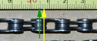
- A small transistor control current passes through the contacts of the breaker, and not the current (up to 8 A) of the primary winding of the ignition coil (erosion and wear of the contacts are eliminated).
- The high voltage current and spark discharge energy increase (this allows the gap between the spark plug electrodes to be increased, makes it easier to start the engine, and makes the engine more economical).
First, let's figure it out
How does a contact-transistor ignition system work?
If the ignition switch 17 is turned on and the breaker contacts are open, then the transistor 21 is locked, since there is no current in its control circuit, i.e. in the emitter-base junction. Current does not pass between the emitter and collector to ground, since the resistance of this junction is very high. When the breaker contacts are closed, current flows in the transistor control circuit (emitter-base), causing the transistor to open. The control current is small (about 0.8 A) and decreases to 0.3 A with increasing speed of the chopper cam. In the contact-transistor ignition system there are two low voltage circuits: the transistor control circuit and the operating current circuit.
Transistor control circuit: positive terminal of the battery 16 - ignition switch 17 - terminals VK-B and K of additional resistors 14 - primary winding 4 of the ignition coil 5 - terminal of the transistor switch 1 - transition electrodes emitter - base of the transistor 21 - primary winding of the pulse transformer 20 - terminal P – contacts 11 and 12 of the breaker – ground – negative terminal of the battery. When the transistor control current passes through the emitter-base junction, the emitter-collector resistance significantly decreases, and the transistor opens, including the operating current circuit (7-8 A).
Low voltage operating current circuit
Positive terminal of the battery 16 - ignition switch 17 - terminals VK-B and K of additional resistors 14 - primary winding 4 of the ignition coil 5 - terminal of the transistor switch 1 - electrodes of the emitter-collector transition of the transistor 21 - terminal M - ground - negative terminal of the battery. When the breaker contacts open, the current in the transistor control circuit stops and its resistance increases significantly. The transistor closes, turning off the low voltage operating current circuit. The magnetic flux of the changing field crosses the turns of the ignition coil, inducing an EMF in the secondary winding, resulting in a high voltage (about 30,000 V), and a self-inductive EMF in the primary winding (about 80-100 V).
High voltage circuit
Secondary winding 6 of the ignition coil 5, rotor 9 of the distributor 10 – spark plugs 7 (in accordance with the engine operating order) – ground – secondary winding 6 of the ignition coil 5.
A pulse transformer is needed to quickly turn off the transistor. When the breaker contacts open, a self-induction EMF is induced in the secondary winding of the pulse transformer, the direction of which is opposite to the direction of the operating current at the base-emitter junction. Thanks to this, the magnetic field and current quickly disappear in the primary winding 4 of the ignition coil 5. Diode 19 and zener diode 18 in the forward direction - past the primary winding of the ignition coil.
It must be remembered that the breaker contacts only pass and interrupt the transistor control current of 0.3-0.8 A. If oil gets on them, an oil film or an oxide layer has formed, then the transistor control current will not be able to pass through the contacts. Therefore, the breaker contacts are washed with gasoline and ensure that they are always clean.
Possible malfunctions and ways to eliminate them
During operation, malfunctions and defects may occur in the vehicle ignition system. The design of the contact transistor ignition system allows, in most cases, the driver to independently search for any faults that have arisen and fix them with his own hands.
Work to determine any defects that have arisen in the system should begin with checking the contacts and condition of the battery, as well as high-voltage connecting wires. After checking these components and if they are in good working order, you should begin identifying other defects, the most typical ones, among which are:
- Difficulty starting the engine, the reasons are the following:
- breakdown of the coil winding,
- violation of the insulation of high voltage wires,
- incorrect adjustment and installation of the ignition,
- oxidation or oiling of the breaker contacts themselves,
- breakdown of the ignition angle corrector,
- poor condition of spark plugs.
- A drop in engine power and a simultaneous increase in fuel consumption is characterized by;
- interruptions in the operation of the cylinders,
- breakdowns of the advance regulator,
- violation of installation parameters.
- The occurrence of glow ignition, in which the ignition of the air-fuel mixture occurs due to contact with the surface of a highly heated part. The occurrence of this process can lead to rapid destruction of engine parts. The main reasons for the appearance are:
- overheating of spark plugs,
- incorrect adjustment and wear of parts of the engine gas distribution mechanism,
- soot deposition in the combustion chamber.
All of the above points can be solved not only by replacing faulty parts, but also by restoring, altering or adjusting individual structural elements of the engine starting mechanism. Perhaps, we can separately highlight cases of glow ignition, since they are almost always eliminated by engine repair, replacement, adjustment or alteration of individual timing elements.
The functions of the individual control systems of the microprocessor ignition system are as follows:
Input device. The signals flowing to the input device from the sensors are converted into a form understandable to the computer, i.e. into a series of YES - NO pulses, which represent numbers in the binary system:
Analog signals, such as battery voltage, are converted into binary code using an ADC.
Watch. The computer operates on data as functions of time. To determine time and time intervals, a precise quartz pulse generator is installed in the computer.
Tires. The individual components of a computer are connected to each other by flat cables known as buses. The buses carry data (data bus), memory addresses (address bus), and control signals (control bus).
Central microprocessor. The microprocessor performs all calculations in a computer. All it can do is add, subtract, divide and multiply, so all programs that the processor executes must consist of these operations. In addition, the processor can perform logical operations.
Permanent memory. This memory can only output the information stored in it, but it cannot be changed in any way. This information is retained in memory even when there is no power. It is impossible to write any new information into it. The permanent memory stores data, such as a map of the values of controlled engine parameters in tabular form, codes, control programs, etc. All this data is entered (stitched) into the permanent memory by the manufacturer. The permanent memory also includes reprogrammable and erasable blocks that can be used by the manufacturer or his representative to update and change the recorded information.
RAM. Current data - sensor signals, control commands and intermediate calculation results are stored in the computer's RAM until they are replaced with new information. When the power is turned off, RAM loses all information stored in it.
Operation of the on-board computer. Information about engine characteristics is stored in computer memory in the form of tables called work tables. These tables are obtained from three-dimensional ignition timing maps and the same maps for the closed period. Worksheets can be generated by computer for various combinations of parameters, but the most common parameters include engine speed, load, temperature and battery voltage. Each of the tables gives its own value for the lead angle, and to determine the truly required angle, all results are compared.
When power is turned on, the microprocessor sends an encoded binary address that indicates which part of the memory it is accessing. A control signal is then sent indicating the direction and sequence of movement of information into or out of the processor. The operation of the processor itself is a series of binary pulses, with the help of which information is read from memory, decoded and executed. Programs for performing operations - arithmetic, logical and transport - are also recorded in memory.
Relay purpose
Any electrical relay is a safety device that is equipped with the ignition system. The contact ignition system is no exception in this regard. Its main purpose is to open and close various sections in the electrical circuits of the car. The devices differ in design and method of control signal, as well as in installation. At the moment, electromagnetic relays are widely used.
In simple words, this type of car electrical equipment protects various elements from high current loads. It simply serves as a switch. In particular, in the ignition system, the relay protects the car starter and generator from exposure to high currents. For example, to start the engine you need to turn the ignition switch and turn on the starter, which, in turn, consumes from 80 to 300A.
In this case, if you do not use a relay, the lock may burn out, as well as some wiring elements. To prevent this from happening, an ignition relay is included in the system. When there is an image of a diode icon on the device’s body, this means that when connecting it, it is important to observe the polarity of the terminals. Otherwise, breakdown is inevitable.
DIAGRAMS—-> AUTO ELECTRONICS DIAGRAMS articles No. 1-50MODERN AUTOMOTIVE IGNITION SYSTEMS
D. Sosnin
On passenger cars equipped with a gasoline internal combustion engine, various electric spark ignition systems are used: contact, contact-transistor, contactless-transistor, electronic digital, microprocessor.
Transistorized ignition systems
Transistor ignition systems are usually divided into two groups:
contact-transistor (CTSZ) and contactless-transistor (BTSP). In a contact-transistor ignition system, the contact pair of the breaker in the primary circuit of the ignition coil is absent and is replaced by a CT transistor switch. But the transistor switch itself is controlled by the base by a contact pair of a mechanical breaker K of the previous design. This made it possible to reduce the rupture current in the contact pair and, due to amplification in the transistor, increase the rupture current in the inductive storage (in the primary winding of the ignition coil). At the same time, the safety factor for the secondary (output) voltage has increased. The operational reliability of the ignition system has become somewhat higher. Along with contact-transistor ignition systems, contact-thyristor systems with a capacitive storage device have also been developed, which have not found wide practical application.
The contactless transistor ignition system (BTIS) is the first system with a purely electronic device for controlling the primary current of the ignition coil and with a non-contact electric pulse ignition timing sensor, which, like the contact pair in a classic chopper-distributor, is located on the movable platform of the drive roller of a mechanical high-voltage distributor . The position of the moving platform relative to the axis of the drive roller (rotation angle) can be adjusted by ignition advance devices (centrifugal and vacuum). The movable platform and the contactless sensor activator installed on it are an electromechanical ignition timing control device. Such a control device, together with a high-voltage distributor, forms the so-called sensor-distributor [1].
The electronic device for controlling the primary current in the BTSZ is structurally designed as a separate unit, which is called a switch. At the output, the switch is connected to the ignition coil, and at the input, it is controlled by an electric pulse input sensor on the distributor.
Thus, the contactless transistor ignition system (Fig. 1) -
this is a combination of an electronic switch K, a sensor-distributor PP, an ignition coil KZ and traditional output executive periphery: high-voltage wires of the GDP and spark plugs.
• Non-contact transistor ignition systems (BTIS) began to be installed on passenger cars in the late 60s and have been constantly improved since then.
Magnetoelectric, induction, electromagnetic generator, parametric, optoelectronic and other converters of mechanical rotation into an electrical signal were tested as non-contact input sensors mechanically driven from the internal combustion engine camshaft (Fig. 2).
The contactless sensor performs the following functions in the ignition system: sets the installation angle* of the ignition timing; controls ignition timing when engine speed and load changes; determines the timing of the internal combustion engine. Based on the combination of the listed functions, the contactless sensor produces the optimal value at the switch input
* The setting angle is the ignition timing at extremely low (idle) engine speeds, when the centrifugal and vacuum regulators are not yet operating. the current value of the ignition timing for various engine operating modes.
Initially, as a simpler and fairly reliable magnetoelectric sensor, it was widely used in practice. But with the development of the Hall effect activator, the latter became the basic element for all subsequent contactless sensors of electronic ignition systems.
BTSZ electronic switches underwent no less significant modernization. Thyristor switches were quickly abandoned, since the ignition system with a capacitive storage device produces a very short high-voltage pulse (no more than 250...300 μs) to the spark plugs, which is not acceptable for most modern gasoline automobile engines.
The first simple transistor switches worked without limiting the amplitude of the primary current, i.e. in the mode of constant duty cycle of charging current pulses for an inductive storage device (domestic switch 13.3734).
In ignition systems with such switches, the amplitude of the high-voltage pulse on the secondary winding of the ignition coil, as in the contact system, depends on the engine speed, as well as on the voltage in the vehicle's electrical system.
Switches with a constant duty cycle (CPS) have been replaced by switches with a normalized duty cycle (SPV), in which the charging current of the inductive storage device is maintained within specified limits by controlled saturation of the output transistor. This protects the output transistor of the switch from current overload, and also stabilizes the amplitude of the charging current when the voltage in the on-board network changes. The output voltage U2 is also stabilized. But limiting the current of a powerful transistor by saturation leads to a significant release of thermal energy at the collector-emitter junction and, as a consequence, to low functional reliability of the ignition system as a whole.
This drawback in switches with a standardized duty cycle can be eliminated by introducing into the circuit an electronic regulator for the energy accumulation time (the time the charge current flows through the inductive storage device). This is how switches with a software controller for accumulation time appeared (switch 36.3734), and after them more advanced switches with adaptive control (switch 3620.3734). The latter, in addition to the main function of timing control, provide higher accuracy in maintaining charge current parameters when the ignition system is exposed to various destabilizing factors (unstable engine operation, environment, aging and derating of radio elements, etc.).
• BTSZ electronic switches are extremely diverse not only in circuit design, but also in technological design. Electronic circuits of switches, initially analog and based on discrete radio elements, were supplanted by integrated circuits with a digital operating principle. Switches based on so-called custom (specially designed for ASZ) large integrated and single-crystal circuits began to appear.
There are more than 60 varieties of contactless ignition systems with electronic switches, mass-produced abroad. Of the domestic transistor switches, the most common are single-channel 36.3734 and 3620.3734, as well as dual-channel 6420.3734 [1].
• As an example of a circuit implementation of a contactless transistor ignition system, let's consider one of the variants of its circuit diagram (Fig. 3).
The VK output stage, in addition to the traditional ignition coil and VT3 transistor switch, contains a number of additional elements. VD1 is a diode to protect transistor switch VT3 from reverse current flow (from inverse switching on) during the capacitive phase of the discharge, when there is a reverse voltage wave in the primary winding of the ignition coil (inverse switching on VT3 is also formed when the battery is accidentally switched back on). VD2 is a stabilizing diode to limit the magnitude of the voltage drop in the emitter-collector section of the closed (open) transistor VT3 (overvoltage protection). Capacitor C1 with the primary winding of the ignition coil forms a series oscillating circuit of shock excitation, which increases the rate of rise of the output voltage of the ignition system. Resistor R3 limits the discharge current of capacitor C1 through the open (closed) switch VT3. In order for the VT3 key to work stably, i.e. when turned on and off, it ensured steep edges and constant amplitude of the primary current pulse in the ignition coil; the control (base) current pulse of transistor VT3 must have steep edges and be large enough in amplitude to deeply saturate the transistor. A pre-amplifier-limiter on transistor VT1 and a stabilizing feedback transistor VT2 work to generate a control current pulse.
The listed elements make up the electrical circuit of the TSZ switch.
• The distributor sensor contains a mechanical ignition timing control device, which includes a magnetic system M of the Hall sensor with field induction B, an EC Hall sensor activator, an amplifier limiter UA, a Schmitt trigger TS, a separating transistor VT and a voltage stabilizer CT.
The sensor-distributor also includes centrifugal (CBR) and vacuum (VR) regulators, a magnetic attenuator A of the Hall sensor and the rotary high-voltage distributor RR itself. It should be noted that the electronic commutator in the BTSZ is only a shaper of the current pulse in the primary winding of the ignition coil, and therefore the rate of rise of the secondary voltage, but the commutator has no direct relation to the formation of the ignition timing. The ignition timing in the BSZ, as in contact systems, is formed by an electromechanical control device - a contactless sensor on the distributor. This circumstance is a fundamental drawback of all contactless electronic ignition systems. The second drawback is the presence of a rotary high-voltage distributor in the system. Further improvement of automotive ignition systems followed the path of eliminating these shortcomings.
Electronic and microprocessor ignition systems
The ignition systems discussed above (KTSZ, BTSZ) currently have limited use, and on imported passenger cars of a high consumer class, starting from the mid-90s, they are not used at all. They were replaced by fourth-generation ignition systems - these are systems with electronic computer control devices and without a high-voltage energy distributor for spark plugs in the output stage. Such systems are usually divided into electronic computing or simply electronic (ESZ) and microprocessor-based (MSZ).
Electronic and microprocessor ignition systems have three fundamental differences from previous systems:
1. Their control devices (CU) are electronic computing units of a discrete operating principle, made using microelectronic technology (on universal or large integrated circuits) and are designed for automatic control of ignition timing.
These devices are called controllers. 2. The use of microelectronic technology, in addition to obtaining reliability advantages, can significantly expand the functions of electronic control. It has become possible to introduce on-board self-diagnosis and the principles of circuit redundancy into the automobile ignition system.
3. The output stages of these systems are in the vast majority of cases multi-channel and, as a result, do not contain a high-voltage ignition distributor.
Electronic and microprocessor ignition systems differ from each other in the way they generate the main ignition signal, i.e. the signal that is supplied from the ECU to the drive release device.
In the ESZ, the main ignition signal is generated using the time-pulse method of converting information from input sensors. This is when the controlled process is specified by the time of its occurrence, with the subsequent conversion of time into the duration of the electrical pulse. Thus, the ESZ controller contains an electronic chronometer and is controlled by analog signals. The component composition of the modern ESZ is shown in Fig. 4.
In the MSZ, the block diagram of which is shown in Fig. 5, to generate the ignition signal, a number-pulse conversion is used, in which the process parameter is specified not by the flow time, but directly by the number of electrical pulses.
The functions of the electronic computer here are performed by a pulse-number microprocessor, which operates from electrical pulses stabilized in amplitude and duration (from digital signals). Therefore, pulse-number converters of analogue signals to digital signals (CHIPs) are installed between the microprocessor and the input sensors in the MSZ ECU.
Unlike an electronic one, a microprocessor ignition system operates according to a control program preset for a given internal combustion engine. Therefore, the computer of the microprocessor ignition system has electronic memory (permanent and RAM).
The control program for a specific engine design is determined experimentally during its development. The test bench simulates all possible engine modes under all possible operating conditions. For each experimental point, the optimal ignition timing is selected and recorded. The result is a set of numerous angle values for the ignition timing, each of which corresponds to a strictly defined set of signals from the input sensors. The graphical representation of such a set is a three-dimensional ignition characteristic, which is shown in the form of a matrix in Fig. 6.
The coordinates of the three-dimensional characteristic are “sewn up” into the permanent memory of the microprocessor and subsequently serve as reference information for determining the ignition timing in real operating conditions of the engine in a car. The reference (taken from memory) ignition timing angle 8 is changed automatically. An increase in angle 8 occurs: with an increase in speed, with a decrease in load and with a decrease in the temperature of the internal combustion engine. A decrease in angle 8 occurs with increasing load, with a drop in speed and with an increase in the temperature of the internal combustion engine.
If the MSZ uses additional sensors in addition to the main ones (for example, a knock sensor in the internal combustion engine cylinders), then the microprocessor corrects the reference value of the ignition timing based on the signals from these sensors. In this case, the adjustment is made for each cylinder separately.
Electronic control units for ESZ and MSZ, in addition to functional and circuitry, also have fundamental design differences.
In the ESZ, the control unit is an independent structural unit and is called a controller (Fig. 7).
The controller inputs receive signals from the input sensors of the ignition system, and at the output, the controller operates on an electronic switch of the output stage (see Fig. 4). All electronic circuits of the controller are low-level (potential), which allows them to be included in other on-board electronic control units (for example, in the fuel injection system ECU).
In MSZ, all control functions are integrated into the vehicle’s central on-board computer and there may be no personal control unit for the ignition system. The functions of the MSZ input sensors are performed by universal sensors of an integrated automatic engine control system. The main ignition signal is supplied to the electronic switch of the MSZ output stage directly from the central on-board computer.
• Despite significant differences in electronic and microprocessor ignition systems, in terms of control devices, the output stages of these systems have identical circuitry and design, in which each spark plug on a multi-cylinder internal combustion engine receives energy for sparking through a separate channel. This distribution is called static or multi-channel.
What does this do to the car ignition system?
It must be remembered that in addition to the usual disadvantages of a mechanical switch (low reliability and low time between failures of rotating and rubbing parts), the classic ignition distributor also has the fact that it implements switching of high-voltage energy through an electric spark.
This, in addition to additional energy losses, leads to uneven burnout of contacts in the insulating cover of the distributor and, as a consequence, to the phenomenon of spark scattering across the cylinders and to low functional reliability of the ignition system. The spread of sparks between the terminals of even a serviceable mechanical distributor can reach 2...3 angular degrees in rotation of the internal combustion engine crankshaft. It is clear that in electronic and especially in microprocessor ignition systems, highly reliable and high-precision in functional terms, the formation of ignition timing in which is realized with an accuracy of 0.3...0.5° for each cylinder separately, the use of a high-voltage mechanical distributor is completely unacceptable. Here, electronic methods of switching channels at a low-potential level directly in the electronic control unit with further static separation of channels at high voltage on multi-terminal or individual ignition coils are acceptable. This inevitably leads to a multi-channel output stage of the ignition system.
Output stages with multi-terminal ignition coils
The implementation of multi-channel energy distribution can be accomplished in ignition systems in several ways.
The simplest of them is the use of a two-terminal high-voltage output transformer or a two-terminal ignition coil in the output stage. This method of channel separation is acceptable for implementation in an ignition system with any type of storage device. Where did this idea come from? It is known that in the ignition system, at the output of which a high-voltage distributor is installed, during the discharge of the accumulator there are two sparks: one main (working) in the spark plug and the other auxiliary - between the distributor runner and the contact of one of its spark plug terminals. The secondary winding of the output transformer (ignition coil) is connected with a high-voltage terminal to the central runner of the distributor, and the other terminal of the winding is zero, since during the discharge of the drive it is connected to the “ground” of the car (see Fig. 3, [1]). The energy of the auxiliary spark in the distributor is wasted uselessly, and they try to suppress this spark in every possible way. It is clear from this that the auxiliary spark from under the distributor cap can be transferred to the second spark plug by connecting it to the first through the cylinder head ground in series. To do this, it is enough to exclude the distributor from the output stage, disconnect the grounded terminal of the ignition coil from the vehicle ground and connect a second electric spark plug to it (Fig. 8).
When sparking simultaneously in two spark plugs, one spark is high-voltage (12...20 kV) and ignites the air-fuel mixture at the end of the compression stroke (working spark). In this case, the other spark is low-voltage (5...7 kV), idle. The phenomenon of redistribution of high voltage from the common secondary winding between the spark gaps in two spark plugs is a consequence of profound differences in the conditions under which sparking occurs. At the end of the compression stroke, shortly before the appearance of the working spark, the temperature of the fuel-air charge is still not high enough (200...300°C), and the pressure, on the contrary, is significant (10...12 atm). Under such conditions, the breakdown voltage between the electrodes of the spark plug is maximum. At the end of the exhaust stroke, when sparking occurs in the exhaust gas environment, the breakdown voltage is minimal, since the temperature of the exhaust gases is high (800...1000°C) and the pressure is low (2...3 atm). Thus, with the static distribution of high voltage using a two-terminal ignition coil (on two series-connected spark plugs - simultaneously), almost all the energy of the high-voltage electric spark discharge falls on the working spark.
• For the first time, a two-terminal coil was used in a contact battery ignition system for a two-cylinder 4-stroke engine. An example is the ignition system for the engine of the Polish car FIAT-126R (Fig. 9). An ignition system similar in operating principle is installed on the domestic OKA car (electronically controlled).
If the internal combustion engine has four cylinders, two two-terminal ignition coils and two separate energy switching channels in the output stage will be required (see Fig. 5). In Fig. Figure 10 shows a diagram of the spark formation sequence in the cylinders of a 4-cylinder, four-stroke engine equipped with an ignition system with two two-terminal ignition coils. A six-cylinder engine will require three dual-terminal ignition coils and three energy channels.
Currently, a number of automotive ignition systems have been developed in which two two-terminal ignition coils are assembled on a common W-shaped magnetic circuit and thereby form one 4-terminal ignition coil (for example, for a VAZ-2110 car). Such a coil has two primary and two secondary windings and is controlled by a two-channel switch. A four-terminal ignition coil can have one secondary two-terminal winding with two primary windings. The secondary winding of such a coil is additionally equipped with four high-voltage diodes - two for each high-voltage terminal [2].
The disadvantage of any ignition system with two-terminal coils is that in one spark plug the spark develops from the central electrode to the mass (side) electrode, and in the second spark plug - in the opposite direction (see Fig. 8). Since the central electrode is pointed and is always much hotter than the side electrode, the flow of charge carriers from its tip during sparking requires the expenditure of less energy than when flowing from the side electrode (thermionic emission begins to appear on the central electrode). This leads to the fact that the breakdown voltage on a spark plug operating in the forward direction becomes slightly lower (by 1.5.2 kV) than on a spark plug with reverse polarity. For modern electronic and microprocessor ignition systems with a large secondary voltage safety factor and controlled energy accumulation time, this is not of fundamental importance.
Output stages with individual static distribution
Modern electronic and microprocessor ignition systems widely use output stages with individual ignition coils for each individual spark plug.
An example is the BOSCH ignition system, integrated into the electronic engine automatic control system (ECAS), which is known as Motronic. In Fig. Figure 11 shows the functional diagram of the Motronic M-3.2 ESAU,
which is installed on four-cylinder engines of AUDI-A4 cars (manufactured after 1995).
The J220 controller has a microprocessor with a memory unit in which the three-dimensional ignition characteristic is stored (see Fig. 6). Based on this characteristic, as well as on the signals from the DO sensor G-28 (engine speed sensor) and the DN sensor G-69 (engine load sensor), the initial ignition timing angle Q(kyu) = F(n) is established. Next, based on the signals from the sensors DH G-40, DT G-62 and DD G-66, the digital microprocessor calculates the current (necessary for this mode of operation of the internal combustion engine) value of the ignition timing angle, which is supplied in the form of the main pulse S using an electronic channel switching circuit ignition into the corresponding channel of the electronic switch K-122. By this time, inductive storage N in this channel is in a charged state (from the +12 V on-board network) and, according to the signal S, is discharged to the corresponding spark plug. After 180° rotation of the crankshaft, the described processes will take place in the next (in the order of engine operation) channel of the commutator.
The main advantages of the ignition system integrated into the Motronic ESAU are as follows:
— individual static distribution of high voltage across spark plugs; — ignition coils with a grounded secondary winding; — all input sensors (Hall sensor, internal combustion engine speed sensor, internal combustion engine temperature sensor, throttle sensors, knock sensor) are generators of electrical signals from non-electrical influences of a non-contact operating principle. The analog signals from these sensors are converted into digital signals in the controller; — selective correction of the ignition timing for detonation (in each cylinder separately); - shutdown of internal combustion engine cylinders in case of interruptions in spark generation (protection of expensive components - oxygen sensor and catalytic gas neutralizer of the vehicle's environmental system from damage); — presence of self-diagnosis and backup functions in the controller.
Output stage with controlled ignition transformer
There are known attempts to use a high-voltage transformer with saturable cores in the multi-channel output stage of an automobile ignition system.
If the magnetic circuit of the transformer is put into saturation mode, then its transformation coefficient drops sharply and the energy from the primary winding to the secondary is not transformed. The electrical circuit of the output stage with a saturation transformer is shown in Fig. 12.
The output transformer has two magnetic cores - M1 and M2, covered by a common primary winding. Each magnetic core is equipped with a separate control winding Wв and Wв") and a separate two-terminal secondary winding (W2′ and W2"). When a current sufficient to saturate the core M1 flows through the control winding Wв', and the winding Wв' is de-energized, then high voltage will be induced only in the secondary winding W2'. If you de-energize the control winding Wв' and pass the saturation current through the winding Wв", then the M2 core will be saturated and the high voltage will be transformed only into the W2 winding".
The ignition system with a saturation transformer is highly reliable, small in size and weight, but its industrial production has not yet been implemented due to significant technical difficulties in manufacturing (the saturation transformer requires toroidal cores made of high-quality permalloy. Winding multi-turn windings on such cores is extremely difficult).
High voltage wires
In ignition systems with a high-voltage mechanical distributor, the length of the high-voltage wires is always significant (20...60 cm).
And since a high-frequency, high-voltage current flows through the wires at the moment of the electric spark discharge in the candles, long wires emit radio interference. Spark plugs are also sources of radio interference. There are three ways to suppress radio interference from ASZ: shielding high-voltage wires, spark plugs, ignition coils and high-voltage distributors; introducing a high-voltage wire of distributed inductance and distributed resistance into the central current conductor; Installing an interference suppression resistor directly into the spark plug insulator.
Screening requires an increase in the secondary voltage margin and makes the ASZ output stage bulky. A high-voltage wire with distributed parameters has insufficiently high structural reliability, complex manufacturing technology and high cost.
In modern ignition systems, spark plugs with an interference suppression resistor of 4...10 kOhm are used, and the length of high-voltage wires is sought to be minimized. The latter becomes possible thanks to the use of individual ignition coils installed directly on the spark plugs (see Fig. 11).
High-voltage wires are divided into low-resistance (up to 0.5 Ohm/m - in outdated wire designs) and high-resistance (1...10 kOhm/m). Wires are marked in two ways: color and text along the wire.
Domestic wires of light brown or variegated colors are low-resistance. Red or pink PVVP-8 wires have a distributed resistance of 2000+200 Ohm/m; blue PVPPV-40 - 2550±250 Ohm/m. On imported high-voltage wires, electrical parameters are often indicated in text along the wire. The content of the text can be deciphered using the company catalogue.
Any of the three above methods for suppressing radio interference leads to a slight drop in the high-voltage output voltage of the ignition system, which sometimes affects when starting a cold engine in slushy winter weather, when the wires are covered with thin frost. To eliminate this drawback, modern microprocessor ignition systems began to use dirt and moisture protection for high-voltage wires and spark plugs (covering the wires in an insulating tube or under a plastic cover along with the spark plugs).
* In conclusion, it should be noted that cars with a central on-board computer (CBC) are still rare. But the prospect is obvious. In the near future, the PCB will become a single electronic control unit, common to all functional systems on board the vehicle, such as: fuel injection, electric spark ignition, anti-lock brakes, differential control of the driving wheels, wheel traction control, etc. and so on. But even with complete integration of control functions into the central on-board computer, the principles of constructing electronic circuits for electric spark ignition systems will remain the same for a long time as in modern microprocessor systems.
Literature
1. D. Sosnin.
Modern automotive ignition systems. Repair&Service, No. 10, 1999, p. 45-47 2. D. Sosnin, A. Feshchenko. Automotive ignition coils. Repair&Service, No. 9, 1999, p. 46-53 3. V.E.Yutt. Electrical equipment of cars. M. Transport. 1995 To be continued REPAIR&SERVICE-10'99
History of the spark
At the dawn of the automobile industry, the ignition system of internal combustion engines was a real headache for engineers.
We recommend: Fan windshield washer nozzles: how they work
Various methods of igniting fuel were invented, and at times they could hardly be called simple and safe. For example, one of the fathers of the industry, Gottlieb Daimler, used a glow tube in his first engines, which had to be heated red-hot with a blowtorch before starting work.
The first prototypes of modern electrical systems appeared at the end of the 19th century.
The so-called magneto, a small generator that produces the necessary voltage to form a spark, enjoyed quite a lot of success among them. The well-known Robert Bosch is considered its inventor.
In fact, the magneto became the progenitor of all spark methods of igniting the mixture, and the contact ignition system that we are talking about today is no exception.
Of course, it is much more advanced than those first devices, but today, in the world of electronics and innovation, it is gradually becoming history.
Mainly, its carriers now are domestic cars - VAZ “classics” and the like. What is she like?
Breakdowns of the contactless ignition system
In a contactless ignition system, similar problems arise: the engine begins to malfunction, stalls, and does not start. The majority of problems are related to contamination of parts. In winter, moisture and salt, which is sprinkled on the roads, settle on spare parts; in summer, dust settles, which penetrates into all the cracks.
The machine starting system, like any part of a single system, ensures comfortable use and uninterrupted operation of all components. Proper operation, timely diagnostics, and high-quality repairs will help all vehicle mechanisms to serve for a long time and work without breakdowns.
Principle of operation
Despite the fact that electronic ignition is the most modern system today, its design is not as complicated as it might seem at first glance.
A system is installed that includes the devices listed above, including an electronic ignition unit, which is also located in the engine compartment and performs its strictly defined function.
It all starts with turning the key in the car's ignition. First, a circuit is closed that connects the battery itself and the ignition system, including all its components. At the same moment, the starter begins to rotate, which spins the engine shafts, injecting the fuel mixture into the combustion chambers.
At the same time, the coil invariably turns the battery current, which has a value of 12 volts, into a powerful stepwise pulse of 30–35 kilovolts. The coil and distributor are controlled by a system of boards and sensors built into the mounting block. At its core, it is artificial intelligence that automatically adjusts the temperature necessary to ensure that the mixture ignites at strictly required times under different operating modes of the internal combustion engine.
Controlling the change in ignition timing on a car allows you to achieve several positive aspects at once. Firstly, the load on the engine is reduced, since the fuel ignites exactly at those moments when the piston is maximally unloaded and ready for further movement along the cylinder. Secondly, fuel consumption is significantly reduced, since more rational use of it is achieved during the stroke.
The importance of the contact-transistor circuit in the development of the automobile
In this case, we considered only two initial stages in the development of the car ignition system. Later it underwent much more significant changes, but the contact-transistor circuit was the first. It was there that possible options for increasing its efficiency were worked out, in particular, moving away from classical contact ignition, and development paths towards the use of non-contact methods for producing a spark were outlined. » alt=»»> The contact-transistor ignition system turned out to be the first step in improving the classical approach to obtaining a spark on a gasoline internal combustion engine, and was a natural stage in the development of the car as a whole, and its individual components in particular.
- Contact transistor ignition system: device and principle of operation
- Scheme of contact transistor ignition in a car
- Operating principle of contact transistor ignition
- What is the difference from the conventional system
- Advantages and disadvantages of contact transistor ignition
Experienced car owners probably know which type of ignition system is installed on their vehicle. It is quite possible that it will be the contact-transistor version we are considering in this topic. What is contact transistor ignition? What is the principle and scheme of its operation? You will find out about this in a few minutes.
Device
The principle of operation of the ignition system is the accumulation and conversion of the low voltage (12V) ignition coil of the vehicle's electrical network into high voltage (up to 30,000V), distribution and transmission of high voltage to the corresponding spark plug and the formation of a spark at the right moment on the spark plug. The following stages can be distinguished in the operation of the ignition system: accumulation of electrical energy, energy conversion, energy distribution over the spark plugs, spark formation, ignition of the fuel-air mixture.
The mechanical breaker directly controls the accumulation process (primary circuit) and is responsible for closing/opening the power supply to the primary winding. The breaker contacts can be seen by looking under the distributor cap. The plastic spring of the movable contact presses it against the fixed contact. They are opened only for a short period of time, namely, at the moment when the advancing cam of the drive roller exerts pressure on the movable contact hammer.
A capacitor is connected to the contacts, which prevents them from burning. The electrical discharge is absorbed and sparking is reduced. In parallel, a low reverse current voltage is created in the circuit, which has a positive effect on the disappearance of the magnetic field.
The breaker is located in the ignition distributor housing and is part of the classic ignition system.
Another important component is the centrifugal ignition timing regulator, a mechanism designed to automatically change the ignition timing depending on the engine crankshaft speed.
The centrifugal regulator is located inside the body of the breaker-distributor. As a rule, it works in conjunction with a vacuum regulator, both of which are part of the breaker-distributor. It is called centrifugal because of the type of force used to implement the change in advance.
On the drive shaft of the breaker there is a plate on which two weights are placed. The weights sit freely on the axles and are tightened by springs. Moreover, the springs have different stiffnesses, which is necessary to prevent resonance. In this case, the breaker cam and a strip with two longitudinal slots are put on the upper part of the drive roller. The longitudinal slots of the bar accommodate the pins of the weights.
Rotation is transmitted from the drive shaft to the cam through weights, pins and a slotted bar. The faster the drive shaft rotates, the more the weights diverge, the greater the angle the cam rotates in the direction of rotation relative to the contact group of the breaker. With increasing speed, the ignition timing increases. As the number of revolutions decreases, the centrifugal force decreases, the springs tighten the weights, the cam turns against the direction of its rotation, the breaker contacts close later and the ignition timing decreases.
If the engine uses non-contact electronic ignition, then the screen of the non-contact spark torque sensor rotates instead of the cam.
If the mechanical chopper is equipped with a transistor switch, then, in this case, it controls only it, and that, in turn, is responsible for controlling the energy storage process. This design is significantly superior to similar devices without a transistor switch, since here the contact breaker is more reliable, which is facilitated by the flow of a lower current through it, which means that contact burning during opening is almost completely eliminated. Accordingly, a capacitor connected in parallel to the contacts of the breaker is simply not needed here, but otherwise the system is completely identical to the classic version. Both systems, which have a mechanical breaker, have a common name - “contact ignition systems”.
Transistor switch systems equipped with a proximity sensor (pulse generator) can be of the inductive type, based on the Hall effect, or of the optical type. In this case, the place of the mechanical chopper is taken by a pulse sensor-generator with a signal converter, which, through a transistor switch, controls the energy storage device. As a rule, the sensor-generator is located inside the distributor, the design of which is no different from the design of a similar part in the contact system, therefore the specified unit is called the “sensor-distributor”.
Armored wires
The contact ignition system and other types of ignition systems are equipped with armored wires that can pass high-voltage voltage through them without damage or loss. In particular, it is an electrical flexible wire with one copper core and multilayer insulation.
In this case, the contact wire is made in the form of a spiral, which eliminates radio interference. As a rule, these wires are installed on spark plugs. With prolonged use, the insulation of the wires may develop microcracks, through which high-value pulses can be lost.