Where does the car begin to move? From the operation of an internal combustion engine, which “starts” after turning the key. In turn, its start is possible thanks to, you guessed it, the ignition coil. Let's take a closer look at its device.
The ignition coil serves to convert the low-voltage voltage of the battery into high-voltage and (on early VAZ models) is a metal cylinder. Car enthusiasts also call the reel body a “bobbin”. Inside it there is a metal core between two windings - primary and secondary.
The initial voltage is applied to the primary winding, where a magnetic field arises. The pulse is then converted into high voltage voltage at the secondary coil, where it can reach up to 500V. The primary winding is a thick metal wire with a small number of turns, and the secondary winding, on the contrary, is a thinner wire with a large number of turns.
At the macro level, the process of generating high-voltage voltage looks like this: first, a spark is ignited, which ignites the fuel-air mixture in the combustion chamber. During combustion of the mixture, a sufficient amount of energy is generated, which sets the engine pistons in motion.
We study the diagram of the ignition coil of a VAZ 2106 car
Ignition VAZ 2101
1 – generator; 2 – ignition switch; 3 – ignition distributor; 4 – breaker cam; 5 – spark plugs; 6 – ignition coil; 7 – battery.
Ignition VAZ 2106
1 – ignition switch; 2 – fuse and relay block; 3 – EPHH control unit; 4 – generator; 5 – solenoid valve; 6 – microswitch; 7 – spark plugs; 8 – ignition distributor; 9 – ignition coil; 10 – battery.
Ignition VAZ 2114
- Diagram of a non-contact ignition system: 1 – non-contact sensor; 2 – ignition distributor sensor; 3 – spark plugs; 4 – switch; 5 – ignition coil; 6 – mounting block; 7 – ignition relay; 8 – ignition switch.
If the ignition coil is faulty, the engine will not start. A characteristic sign of a faulty coil is its increased temperature when the ignition is turned off. This is easy to determine by touch.
Signs of a faulty ignition module may include the following:
- hesitant engine starting or failure to start;
- failures during sudden changes in speed;
- high fuel consumption;
- two cylinders do not work, the engine is feverish;
- lack of dynamics;
- a sharp drop in power;
- drop in power and thrust after warming up.
These symptoms may not only be caused by the ignition module. To determine the malfunction, it is enough to spend a few minutes diagnosing spark plugs, high-voltage wires and caps. This will eliminate the remaining elements of the ignition system and make sure that it is the ignition module that is faulty.
Checking the ignition coil is performed in one of 2 ways. The simplest one is to remove the central wire from the breaker-distributor, bring it to the motor housing and turn it with the starter, and a running spark should appear.
If it is absent, the reason will be a malfunction of a system element such as the ignition coil.
To check the module in the second way, we only need a multimeter, then follow the step-by-step instructions:
- We check the power supply and the presence of pulses supplied from the ECU. We check the power between the central terminal (15) of the wire block connected to the module and the engine ground. When the ignition is on, the voltage should not be less than 12 V. Otherwise, either the battery is dead or the ECU does not work.
- We check the pulses from the ECU on the wiring block. We install one tester probe on connector 15, the second on the far right, then on the far left. The assistant cranks the engine with the starter, and at this time we record short-term voltage surges with a tester. If there are no impulses from the ECU, it is he who is to blame.
- We check the resistance on the secondary windings of the coils. We put the tester in resistance measurement mode and measure it at the high-voltage terminals of the module cover. Between pins 1 and 4 and pins 2-3, the resistance should be 5.4 kOhm. Otherwise, the module must be replaced.
- We check the resistance of the primary windings between contacts 15 and the rightmost, then the leftmost terminals. Nominal - 0.5 Ohm. Deviation is not allowed.
- Check the module for a short circuit. In ohmmeter mode, install one multimeter probe on the central terminal, the second on the metal body. There shouldn't be any resistance. If the device detects at least some resistance (other than unity or infinity), the module must be replaced.
Useful: Pinout of VAZ air flow sensor. Checking and repairing the air flow sensor
The procedure for removing and installing the ignition coil on old VAZ models:
- First, disconnect the central high-voltage wire leading to the distributor (ignition distributor).
- Disconnect all power wires from the coil contacts. Since they are fastened with nuts, you will need an 8 wrench for this.
- If you don’t know which wires to connect to which connector later, it’s better to immediately remember or mark them somehow, so that later during installation you can connect them correctly.
- Unscrew the coil housing. It is attached to a clamp (clamp), which is pressed to the car body with two nuts.
- After the work has been done, you can remove the ignition coil and replace it if necessary.
For new type VAZ cars:
- We remove the “minus terminal” from the battery.
- Remove the top protective cover of the engine. If the engine volume is 1.5 liters, then this part is missing and this step is skipped.
- We remove the high-voltage wires from the coil.
- Now, using a 13mm wrench, unscrew the two fasteners.
- Using a 17mm wrench, loosen one bolt securing the coil.
- We take out the module.
- Use a hexagon to unscrew the coil from the holder.
- Assembly is carried out in reverse order.
Particular attention should be paid to the connection, since high-voltage wires must be located in the strict order provided for by the design. If this is not done, the car will stall or the engine may not start at all.
Replacing the ignition coil on a VAZ is quite simple. Even a novice motorist can do this in his garage, and if everything seems too complicated, contact a car service center. Particular attention should be paid to the choice of product, since this will determine how well the engine and ignition system will work.
Despite the similarity in engine design, the ignition system of the 1.5-liter injection 16-valve engine differs from the 1.6 16-valve engine.
The 1.6 liter engine uses an electronic contactless ignition system with individual coils on each spark plug. Therefore, there was no need for an ignition module.
Such a system is more reliable and cheaper to operate, since if one coil fails, there is no need to replace the entire module.
The design of the module remains the same - two ignition coils (for cylinders 1-4 and 2-3) plus switch keys in a single block. The spark is supplied to the cylinders in pairs using the idle spark method.
This means that sparking occurs in two cylinders simultaneously - in one on the compression stroke (working spark), in the second on the exhaust stroke (idle spark).
2— 5,00
If during the operation of the vehicle the engine began to “trouble”, its power characteristics decreased, and problems appeared with starting the power plant, then the root of the evil should be sought in the ignition system. If you have to test a car with a carburetor engine, then the task becomes simpler.
To test this system, you will need an electrical device such as a multimeter, as well as screwdrivers with different heads and insulated pliers for working under voltage. It is necessary to observe safety precautions when working with the ignition system, because... high voltage electric current flows in the circuit. It is recommended to have rubber gloves or insulated pliers.
The schematic diagram of the VAZ 2106 ignition coil is located here. The figure shows how the ignition coil is connected in the standard version.
The ignition coil, the price of which is acceptable for most Russian motorists, has the nomenclature code 8352.12. and is an oil-filled tank with an open-type magnetic wire.
The standard ignition coil of the “six”, which is easy to buy at any specialized auto parts store, is equipped with 3 contact terminals: “B”, “K” and an output for the central high voltage wire.
The ignition coil is connected in the following way: the positive wire of the battery is connected to terminal “B” through the ignition switch contact.
Output “K” is connected to the output contacts of both windings of the ignition coils and the negative wire of the battery through the switch.
The high voltage output is connected to another contact of the secondary winding and a high voltage wire contact leading to the breaker distribution element, which, with the rotational movement of the slider, distributes the high voltage current to the spark plugs.
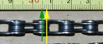
What malfunctions of the VAZ 2106 ignition coil can be determined by checking? If we exclude such defects as unstable contact of the product with the electrical wiring due to weak fastenings, then the main malfunction of the ignition coil is a weak spark, which cannot “break through” a gap of more than 5 mm. A working ignition coil in good condition should “break through” a gap of about 15 mm. Otherwise, the “reel” is considered faulty.
A routine check of the ignition coil is carried out on a product located in the electrical circuit of the vehicle. The main goal of the activities being carried out is to measure the resistance of the ignition coil of the VAZ Shokha, namely, to measure the resistance values of all windings and the insulation resistance to ground.
Operating procedure:
- Disconnect the negative wire from the battery.
- We remove the electrical wiring elements from the output contacts of the coil.
- To carry out repair work, you need to acquire a set of ordinary plumbing tools, a megohmmeter or other similar device.
- We measure the resistance of the primary winding; to do this, we connect the megger contacts to the low voltage terminals, which should be cleaned of dirt. For products with number 3122.3705 according to the nomenclature, the resistance of the ignition coil should be 0.43 ± 0.04 Ohm. For products with number 8352.12 according to the nomenclature, the resistance of the ignition coil should be 0.42 ± 0.05 Ohm.
- Then we test the resistance of the secondary winding, i.e. We connect the limit switch of the megohmmeter to output “B” of the product, and connect the other output to the high voltage contact. For products with number 3122.3705 according to the nomenclature, the resistance of the ignition coil should be 4.08 ± 0.40 Ohms. For products with number 8352.12 according to the nomenclature, the resistance of the ignition coil should be 5.00 ± 1.00 Ohms.
- And at the final stage it is necessary to test the insulation resistance to ground, i.e. We connect the first output of the megger to the body of the product, and the second in turn to three output contacts - 2 low voltage channels and 1 high voltage channel. All megohmmeter measurements must be at least 50 Megohms. If the measurement indicators are different, it is necessary to replace the product.
Ignition VAZ 2106
Repair
So, for the VAZ 2110 the most common problem is the disappearance of voltage on cylinders 2 and 3. After some time, the engine starts working normally again if you press the rear plate of the module.
You should not put up with such a situation; it is better to immediately check the functionality of the unit, restore or replace it completely.
Removing the module
The procedure is quite simple.
- Disconnect the negative cable from the battery.
- Remove the plastic cover that covers the motor.
- Remove the wires from the spark plugs.
- Disconnect the wires from the ignition module. Their numbering is indicated on special white rings. And the cylinder number is indicated on the ignition module housing.
- Disconnect the connector from the ignition module.
- Using a 10mm socket, unscrew the three nuts that hold the block we are looking for.
- Carefully remove it, after which you can begin further work.
Now let's move directly to working with the module:
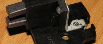
- Open the aluminum plate on the ignition module. A flathead screwdriver is useful for this.
- Inside you will find a small printed circuit board with electronic components. It is covered with a transparent layer of silicone, which will have to be removed.
- There are also wires that connect the board to the connector contacts. They are made of aluminum, so they can tear quickly.
- Tear off all the wires from the contacts, don’t be afraid. Others will be installed in their place. By the way, experts recommend using stranded wires used in computer mice.
- The ignition module circuit includes two switches and two powerful transresistors. If you decide to change these elements, you need to know that the switches are manufactured by SGS-THOMSON (model L497D1), and the transistors are of the BU931 type.
- The contacts are made of aluminum, so you will need a special flux to work with this metal.
- We solder the wiring to the board. It is more difficult to solder to the transistor collectors, since they are covered with a special material, the soldering of which is problematic. Therefore, try to hide the top coating from the element as carefully as possible. To prevent the soldering iron from transferring all the heat to the plate, place it on the stove and heat it to 180 degrees Celsius.
- Solder the wires to the contacts on the module so that they are as short as possible.
- Cover the areas where you soldered with varnish. Regular nail polish borrowed from your wife will do.
- Check if the ignition module is working.
- If everything is fine, coat the inner surface with a special autosealant, then reassemble in the reverse order.
- Upon completion of assembly, the wiring should be positioned fairly freely. Make sure that they are not compressed inside the box and that the integrity of the connections is not broken.
Briefly about ignition
To understand why there is a reel in a car (this is a popular name), and what part it takes in ensuring movement, you need to at least generally understand the structure of ignition systems.
Be sure to read
About all types of ignition systems
A simplified diagram of how the reel works is shown below.
The positive terminal of the coil is connected to the positive terminal of the battery, and the other terminal is connected to the voltage distributor. This connection scheme is classic and is widely used on VAZ family cars. To complete the picture, it is necessary to make a number of clarifications:
- The voltage distributor is a kind of dispatcher that supplies voltage to the cylinder in which the compression phase has occurred and the gasoline vapors should ignite.
- The operation of the ignition coil is controlled by a voltage switch; its design can be mechanical or electronic (contactless).
Mechanical devices were used in old cars: the VAZ 2106 and the like, but now they are almost completely replaced by electronic ones.
Coil device
To test this system, you will need an electrical device such as a multimeter, as well as screwdrivers with different heads and insulated pliers for working under voltage. It is necessary to observe safety precautions when working with the ignition system, because... high voltage electric current flows in the circuit. It is recommended to have rubber gloves or insulated pliers.
The schematic diagram of the VAZ 2106 ignition coil is located here. The figure shows how the ignition coil is connected in the standard version.
The ignition coil, the price of which is acceptable for most Russian motorists, has the nomenclature code 8352.12. and is an oil-filled tank with an open-type magnetic wire.
The standard ignition coil of the “six”, which is easy to buy at any specialized auto parts store, is equipped with 3 contact terminals: “B”, “K” and an output for the central high voltage wire. The ignition coil is connected in the following way: the positive wire of the battery is connected to terminal “B” through the ignition switch contact. Output “K” is connected to the output contacts of both windings of the ignition coils and the negative wire of the battery through the switch.
The high voltage output is connected to another contact of the secondary winding and a high voltage wire contact leading to the breaker distribution element, which, with the rotational movement of the slider, distributes the high voltage current to the spark plugs.
The VAZ 2106 ignition coil is one of the components of the ignition system, which also consists of a lock, high-voltage wires, a distributor and spark plugs.
The coil is a high-voltage pulse transformer. They consist of a core on which a secondary winding of thin wire is wound. A primary winding made of thick wire is wound on top of the secondary winding. Each of the windings is connected to a battery.
The core's job is to enhance the magnetic field. When the circuit breaks, a high-voltage current appears in the secondary winding, which is supplied to the spark plug, where a breakdown occurs and a spark jumps.
• lock; • distributor; • candles; • cables.
• a core with a primary winding made of thin wire; • secondary winding - it is made of thicker wire.
regulators, centrifugal and vacuum (CR and VR);
high-voltage wires (VP).
An ignition coil (IC) with two windings makes it possible to obtain a high current by converting a low voltage.
The mechanical breaker (MP) is structurally made together with a mechanical distributor (MD) in one housing - a distributor. It ensures the opening of the primary winding of the short circuit.
A mechanical distributor (MD) in the form of a rotor with a contact cover distributes current to the spark plugs.
The centrifugal regulator (CR) allows you to change the advance angle (AF) in proportion to the crankshaft speed. Structurally, the CR is made in the form of two weights. During rotation, they act on the movable plate on which the MP cams are located.
The vacuum regulator (VR) makes adjustments to the advance angle (TAA) depending on the load. When the position of the throttle valve (V) changes, the pressure in the cavity behind the V changes. The VR reacts to the degree of vacuum and adjusts the value of the SOP.
The modern bobbin is a simplified version of the Ruhmkorff induction coil. It was named after the German-born inventor Heinrich Ruhmkorff, who was the first to patent a device in 1851 that converts low-voltage direct voltage into high-alternating voltage.
To understand the principle of operation, you need to know the structure of the ignition coil and the basics of radio electronics.
This is a traditional, common VAZ ignition coil, used for a long time and on many other cars. In fact, this is a pulse high-voltage transformer. On a core designed to enhance the magnetic field, a secondary winding is wound with a thin wire; it can contain up to thirty thousand turns of wire.
On top of the secondary winding is a primary winding made of thicker wire and with fewer turns (100-300).
The windings at one end are connected to each other, the second end of the primary is connected to the battery, the secondary winding with its free end is connected to the voltage distributor. The common point of the coil winding is connected to the voltage switch. This entire structure is covered by a protective housing.
A direct current flows through the “primary” in the initial state. When a spark needs to be formed, the circuit is broken by a switch or distributor. This leads to the formation of high voltage in the secondary winding. Voltage is supplied to the spark plug of the desired cylinder, where a spark is formed, causing combustion of the fuel mixture. High-voltage wires were used to connect the spark plugs to the distributor.
The single terminal design is not the only one possible; there are other options.
- Double spark. The dual system is used for cylinders that operate in the same phase. Let's assume that compression occurs in the first cylinder and a spark is needed for ignition, and in the fourth cylinder there is a purge phase and an idle spark is formed there.
- Three-spark. The principle of operation is the same as that of a two-terminal one, only similar ones are used on 6-cylinder engines.
- Individual. Each spark plug is equipped with its own ignition coil. In this case, the windings are swapped - the primary is located under the secondary.
How to check the ignition coil
The main parameter by which the performance of the reel is determined is the resistance of the windings. There are average indicators that indicate its serviceability. Although deviations from the norm are not always an indicator of a malfunction.
Using a multimeter, you can check the ignition coil according to 3 parameters:
- primary winding resistance;
- secondary winding resistance;
- presence of a short circuit (insulation breakdown).
We check the primary winding by attaching probes to contacts B and K.
| Coil type | Resistance, Ohm |
| VAZ 2106 (contact system) | 3,07-3,5 |
| 27.3705 (contactless, M, P) | 0,45± 0,05 |
| 3122.3705 (N, W) | 0,43± 0,04 |
| 8352.12 (M, R) | 0,42± 0,05 |
| 027.3705 (M, R) | 0,43± 0,04 |
| 27.3707-01 (M, R) | 0,42± 0,05 |
| ATE1721 (M, R) | 0,43± 0,05 |
| M – oil-filled | |
| C – dry | |
| P – open magnetic circuit | |
| Z – closed magnetic circuit | |
When measuring the “secondary” we connect one probe to contact B, and the second to the high-voltage terminal.
| Coil type | Resistance, KOhm |
| VAZ 2106 (contact system) | 5,4-9,2 |
| 27.3705 (contactless, M, P) | 5±1 |
| 3122.3705 (N, W) | 4,08±0,4 |
| 8352.12 (M, R) | 5±1 |
| 027.3705 (M, R) | 5±1 |
| 27.3707-01 (M, R) | 5±1 |
| ATE1721 (M, R) | 5±1 |
The insulation is measured through terminal B and the coil body. The device readings should be at least 50 MΩ.
It’s not always common for a car enthusiast to have a multimeter at hand and experience in using it; on a long journey, checking the ignition coil using this method is also not available.
other methods
Another method, especially relevant for old cars, including VAZs, is to check the spark. To do this, the central high-voltage wire is placed at a distance of 5-7 mm from the motor housing. If a blue or bright purple spark flashes when you try to start the car, the reel is working normally. If the color of the spark is lighter, yellow, or absent altogether, this may confirm that it is broken or the wire is faulty.
There is an easy way to test a system with individual coils. If the engine stalls, you just need to disconnect the power to the coils one by one while the engine is running. We disconnected the connector and the operating sound changed (the machine stalled) - the coil is fine. The sound remains the same - there is no spark to the spark plug in this cylinder.
Checking the ignition coil is performed in one of 2 ways. The simplest one is to remove the central wire from the breaker-distributor, bring it to the motor housing and turn it with the starter, and a running spark should appear. After this, we check the energy supply to a separate spark plug, for which we unscrew the working spark plug, bring its contact to ground and attempt to start the engine.
Short circuit testing is performed in the following stages:
- visual inspection;
- checking for voltage;
- measuring resistance using an ohmmeter;
- checking for spark.
A visual inspection reveals mechanical damage to the surface, the presence of oil stains, mud deposits, and the reliability of connections and electrical contacts. To check the voltage supply to the unit, you need to turn on the ignition and measure the voltage between terminal “B” and ground with a voltmeter. It should be 12 V. If there is no voltage, then the problem is in the ignition switch.
To check the windings, the multimeter must be set to resistance measurement mode. To check, one multimeter probe is connected to the output of both windings, the second probe is connected to the output of the primary winding. In this case, the device will show the resistance of the primary winding (video author - altevaa TV).
By connecting one tester probe to the terminal of the primary winding, and the second to the central terminal of the short circuit, you can measure the total resistance of both windings. Using this method, you can also obtain the resistance value of the secondary winding.
When measuring resistance on the windings, the readings must correspond to the following values:
- for the primary winding - 3-3.5 kOhm;
- for the secondary winding - 5-9 kOhm.
If the values differ from those given above, the unit is faulty and requires repair. A sign of a short circuit fault is the presence of a short to ground.
Do not touch the high voltage wire to the motor housing, as this will lead to breakdown of the short-circuit winding and disable it.
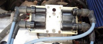
In VAZ 2106 cars with an injection engine there is no distributor-breaker; two short circuits are used, which are located on the cylinder head cover. The voltage in the network is checked by a special controller. A common cause of short circuit malfunction is overheating or interturn short circuit of the windings. This occurs if the engine is operated with excessive spark plug gaps or if there is no contact in the connections.
A common cause of component failure is faulty high-voltage wires and spark plugs. The short circuit often fails if the ignition is turned on for a long time and the engine is not running. At elevated temperatures, the insulating material of the windings dries out and crumbles. This causes a short circuit. The short circuit becomes unusable and must be replaced.
A possible reason for a non-working short circuit may be poor contact with the electrical wiring. In this case, you need to tighten the contacts and clean the terminals from oxidation.
The cause of the malfunction is often a weak spark. In this case, a spark cannot penetrate a gap exceeding a distance of more than 5 mm. A working unit should have a gap of about 15 mm. Otherwise, the short circuit is faulty and needs to be replaced.
The VAZ 2106 ignition system includes:
- ignition coil;
- distributor;
- spark plug;
- low voltage wires;
- high voltage wires;
- egnition lock;
- ignition relay.
Diagram of the VAZ 2106 ignition system: 1 - generator; 2 - battery; 3 — four-pin connecting block; 4 — ignition coil; 5 — distributor (distributor); 6 — ignition switch; 7 - high voltage wires; 8 - spark plugs
Purpose
The ignition coil is a high-voltage pulse transformer. Its main function is to create a high voltage in the circuit to form a spark. A spark, in turn, is necessary to ignite the fuel-air mixture during operation of an internal combustion engine. If the coil is faulty, the car simply will not be able to start.
The ignition coil is cylindrical in shape
Location
On the VAZ 2106, the ignition coil is installed in the left front corner of the engine compartment. It is fixed to the mudguard with two nuts and can be easily removed if necessary.
The VAZ 2106 ignition coil is mounted in the upper front corner under the windshield frame
The central part of the coil is the core, on which about 30 thousand turns of thin wire of the secondary winding are wound. A layer of thick wire is wound onto the secondary winding - the primary winding.
Some ends of both windings are connected to the battery, the other to a distributor that controls the power supply. During the winding process, the thin and thick wire will have points of contact. One of these points must be connected to a voltage switch.
In this case, the function of the coil core is reduced to enhancing the magnetic field.
When connecting the coil, it is important to follow the order of connecting the individual wires in accordance with their functions
The design of classic VAZ cars does not place excessive demands on the ignition coil. The coil must meet certain parameters and produce the required voltage. On the VAZ 2106 you can install coils from the following manufacturers:
- ERA is a domestic manufacturer of components for various cars, offering ignition coils for the VAZ 2106 starting at RUB 1,350. Such coils have a very limited service life.
- MZATE-2 offers reliable ignition coils at prices starting from 600 rubles. In addition to the low price, the products are easy to install and are available in almost every car dealership.
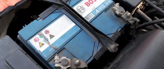
- Bosch is a trusted manufacturer of auto parts. Despite the high price (from 2,700 rubles), German-made coils are extremely reliable and have the longest service life.
- SOATE is another domestic manufacturer that sells ignition coils for the VAZ 2106 at prices starting from 700 rubles.
SOATE offers a complete set of ignition system elements
The most reliable coils are Bosch - these are powerful, high-quality devices with maximum service life.
Many people believe that heating the coil during operation is a malfunction. However, it is not. A high voltage current passes through the winding, so the coil may heat up slightly.
The main signs of a faulty coil are as follows.
- No spark. This is the most common symptom in which it is impossible to start the engine. In this case, the coil must be replaced.
- When starting, the engine starts to run and immediately stalls. This is also caused by a faulty coil.
- The engine runs stably and does not overheat, but fuel consumption increases.
Opening the hood, you can see there is no spark when starting the engine.
There are also a number of indirect signs of coil malfunction, which until a certain time do not affect the performance of the engine, but will appear in the near future:
- Mechanical damage to the coil body, which can be seen with the naked eye.
- Breaks in the coil windings.
- Coil overheating.
In addition, the driver should be wary of the uneven distribution of carbon deposits on the spark plugs, as well as the inability to start the engine the first time. If there is even the slightest doubt about the performance of the ignition coil, it is better to check it immediately, avoiding the possibility of it failing on the road.
Experts identify two reasons why the ignition coil may fail.
- Using low quality spark plugs. Cheap spark plugs produce reverse gases, which, in turn, can cause breakdowns in insulators. As a result, the coil tips will quickly fail, and you will have to change the coil along with the spark plugs.
- Severe overheating of the coil body. The coil itself must operate in any temperature conditions. However, if the engine overheats frequently, the coil will also experience thermal overload. This usually happens when driving aggressively or there are problems with the engine cooling system.
Checking the performance of the coil
How to check the ignition coil of a VAZ-2106 car at home? The best way is to use a multimeter or ohmmeter. Winding testing using this equipment is carried out as follows:
- to make sure that the primary winding is in good condition, connect an ohmmeter to its side terminals and look at the resistance readings. For a fully working ignition coil, it should be at least 3-4 ohms. Otherwise, the device will need to be repaired or replaced;
- to check the secondary winding, one of the ohmmeter outputs is connected to the same side one, and the second one is connected to the central terminal on the pulse transformer itself. The normal value is somewhere in the range of 7.5-9.2 ohms. To get accurate data, it is better to consult your vehicle's owner's manual. If there are any deviations, the ignition coil must be replaced.
Before performing the checks described above, you must disconnect the negative terminal from the battery. This will help eliminate the risk of short circuits.
VAZ models 8 and 16 valves
Despite the similarity in engine design, the ignition system of the 1.5-liter injection 16-valve engine differs from the 1.6 16-valve engine. The 1.6 liter engine uses an electronic contactless ignition system with individual coils on each spark plug. Therefore, there was no need for an ignition module. Such a system is more reliable and cheaper to operate, since if one coil fails, there is no need to replace the entire module.
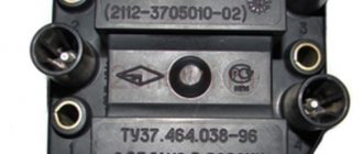
The 16-valve 1.5-liter VAZ 2112 injection engine used the same non-contact ignition system as the 8-valve engine, but a different ignition module was installed. Its catalog number is 2112-3705010. The design of the module remains the same - two ignition coils (for cylinders 1-4 and 2-3) plus switch keys in a single block.
Symptoms of a problem
It is extremely rare for two built-in coils to fail at once, so it is more likely to be possible to start the engine with a faulty unit. However, even an inexperienced driver will immediately suspect something is wrong. The malfunction will appear as follows:
- unstable (floating) idle speed;
- the engine has difficulty picking up speed;
- characteristic sound of the engine (triple);
- jerking when accelerating (while moving).
Operating a car with such a breakdown is possible (you can drive to a garage or car service station), but it is not advisable unless absolutely necessary.
Similar signs of unstable engine operation are possible with a number of other ignition or fuel supply faults. To differentiate possible breakdowns, the performance of the ignition unit should be determined. It would be useful to check the contacts of the wires coming to the device, as well as their integrity.