Features of the design of the power system of the Daewoo Nexia car
The power supply system includes elements of the following systems:
- fuel supply system, which includes a fuel tank 44, an electric fuel pump 36, pipelines 18, 19, 20, 23, 30, hoses 16, 32, a fuel rail with injectors and a fuel pressure regulator. as well as fuel filter 25;
- an air supply system consisting of an air filter, air supply pipes, and a throttle assembly;
- fuel vapor recovery system, which includes an adsorber 3 and connecting pipelines 54, 59.
The functional purpose of the fuel supply system is to ensure the supply of the required amount of fuel to the engine in all operating modes.
DONC and SONC engines are equipped with an electronic engine management system with distributed fuel injection. In the distributed fuel injection system, the functions of mixture formation and dosing of the air-fuel mixture into the engine cylinders are separated: the injectors carry out dosed injection of fuel into the intake pipe, and the amount of air required at each moment of engine operation is supplied by a system consisting of a throttle unit and an idle speed regulator. This control method makes it possible to ensure the optimal composition of the combustible mixture at each specific moment of engine operation, which allows you to obtain maximum power with the lowest possible fuel consumption and low exhaust gas toxicity. The fuel injection system and ignition system are controlled by an electronic engine control unit, which continuously monitors, using appropriate sensors, the engine load, the vehicle speed, the thermal state of the engine, and the optimal combustion process in the engine cylinders.
The main sensor for the fuel injection system is the oxygen concentration sensor 3 (see figure below) in the exhaust gases (lambda probe). It is installed in the exhaust manifold 2 of the engine and, together with the engine control unit 5 and injectors 1, forms a control circuit for the composition of the air-fuel mixture supplied to the engine.
Based on the signals from the oxygen concentration sensor, the engine control unit determines the amount of unburned oxygen in the exhaust gases and accordingly evaluates the optimal composition of the air-fuel mixture entering the engine cylinders at each time.
Having detected a deviation of the composition from the optimal 1:14 (fuel:air), which ensures the most efficient operation of the exhaust gas catalytic converter, the control unit changes the composition of the mixture using injectors. Since the oxygen concentration sensor is included in the feedback circuit of the engine control unit, the air-fuel mixture control loop is closed.
A feature of the engine control system A15SMS and F16MF of the Nexia car is the presence, in addition to the control sensor, of a second oxygen concentration sensor 7, diagnostic, installed at the outlet of the exhaust gas converter 6. Based on the composition of the gases passing through the neutralizer, it determines the efficiency of its operation.
Rice. Diagram of the air-fuel mixture control circuit: 1- injector; 2- exhaust manifold; 3- control oxygen concentration sensor; 4- engine; 5- electronic engine control unit; 6- catalytic converter of exhaust gases; 7 - diagnostic oxygen concentration sensor.
The fuel tank is welded and stamped. The fuel tank is installed under the floor of the body in its rear part and secured with two steel clamps 2 and 7.
Rice. Fuel tank: 1- fuel filter; 2.7 - fuel tank mounting clamps; 3- fuel line for draining fuel from the ramp; 4- fuel level indicator sensor; 5- filling pipe; 6- fuel tank; 8 - fuel supply line.
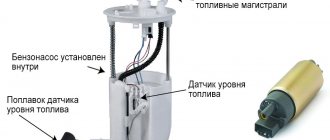
To prevent fuel vapors from entering the atmosphere, the fuel tank is connected by pipeline 8 to the adsorber. To reduce noise levels, sound insulation is glued to the fuel tank. An electric fuel pump is installed in the flange hole in the upper part of the fuel tank, the fuel level indicator sensor 4 is installed in the same hole in the lower part, and in the rear part there is a pipe for connecting the filling pipe 5. From the pump, fuel is supplied to the fuel filter 1, installed at the bottom on the base of the body, and from there it enters the engine fuel rail, mounted on the engine inlet pipe. From the fuel rail, fuel is injected by injectors into the intake pipe. Excess fuel is drained into the fuel tank through a fuel pressure regulator mounted at the rear end of the fuel rail. Fuel lines of the power supply system are combined in the form of interconnected steel pipelines and polymer hoses.
It is prohibited to replace steel pipelines with hoses, copper or aluminum tubes, since only steel pipelines satisfy operating conditions under high vibrations and pressure.
The hoses of the power supply system are made using a special technology from oil- and petrol-resistant materials. The use of hoses that differ in design from those recommended may lead to failure of the power system and, in some cases, to a fire.
Submersible fuel pump with electric drive, rotary type, with a coarse fuel filter. The fuel pump provides fuel supply and is installed in the fuel tank, which reduces the possibility of vapor lock formation, since the fuel is supplied under pressure and not under vacuum. The fuel pump supplies fuel from the fuel tank through the main fuel filter to the injector rail at a pressure of more than 284 kPa. The non-demountable fuel pump cannot be repaired. If it fails, it must be replaced.
The fine fuel filter is full-flow, secured with a clamp to the base of the body in its rear part on the right side. The fuel filter is non-separable, with a paper filter element in a steel housing.
The injector fuel rail is a hollow tubular part with holes for installing injectors, a fuel pressure regulator and a fitting for connecting a high pressure fuel line. The injectors are attached to a ramp from which fuel is supplied to them, and with their sprayers they enter the opening of the intake pipe.
The injector is designed for dosed injection of fuel into the engine cylinders and is a high-precision electromechanical valve. The fuel pressure regulator is installed on the fuel rail and maintains constant fuel pressure in the central channel of the rail in all engine operating modes. Regulation of the fuel pressure supplied to the injectors is based on the principle of monitoring the pressure difference in the ramp and inlet pipe, which under any conditions should be 300 kPa (0.3 kgf/cm3). The electric fuel pump delivers more than is needed to keep the system operational. Therefore, when the engine is running, part of the fuel is constantly drained into the fuel tank using a pressure regulator. Depending on the vacuum in the intake pipe, the pressure regulator reduces or increases the drainage of excess fuel, maintaining constant pressure in the rail.
Next page""""""- 10. 11. 12. 13. 14. 15. 16. 17. 18. 19. 20. 21. 22. 23. 24. 25. 26. 27. 28. 29. 30. 31. 32. 33. 34.
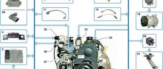
16 Fuel and exhaust system Daewoo Nexia repair Deo Nexia Location of the main system components of a 1.5-liter engine (SOHC) with MSVT ELECTRICAL WIRING ECU, FUSES AND CONNECTORS C1.
ECU C2. DIAGNOSTIC CONNECTOR NW. “ENGINE MAINTENANCE REQUIRED” (ETD) ALARM C5. MASS WIRE ECU C6. FUSE PANEL C8. CONNECTOR FOR CHECKING FUEL PUMP UNITS WORKING INDEPENDENTLY FROM ECU N1. FORCED Crankcase VENTILATION SYSTEM (FCVV) N2. TANK FOR COLLECTION OF GASOLINE VAPOR (LOCATED UNDER THE MUDFLAP) N3. OIL PRESSURE SWITCH (LOCATED IN THE CYLINDER BLOCK UNDER THE INDUCTION PIPE) N4. AIR CLEANER COMPONENTS WORKING TOGETHER WITH THE ECU 1. FUEL INJECTORS 2. IDLE VALVE 3. FUEL PUMP RELAY 4. DISTRIBUTOR WITH IGNITION ADVANCE SYSTEM 8. COOLING FAN RELAY 9 AIR CONDITIONING COMPRESSOR RELAY 10. IGNITION COIL SENSORS A. ABSOLUTE PRESSURE SENSOR IN THE INDUCTION PIPE (DAP) B. OXYGEN CONCENTRATION SENSOR IN EXHAUST GAS C. THROTTLE POSITION SENSOR (TPS) D. COOLANT TEMPERATURE SENSOR (TFL) E. AIR TEMPERATURE SENSOR IN INLET T PIPELINE (DTV) F. VEHICLE SPEED SENSOR (VSA) ) M. SENSOR FOR TURNING THE TRANSMISSION CONTROL LEVER INTO THE PARKING OR NEUTRAL POSITION (VSN) Fuel system
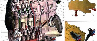
1. FUEL TANK CAP 2. BOLT 3. TANK FILLER GASKET 4. TANK FILLER 5. FILLER CLAMP 6. BOLT 7. CLAMP 8. WORM CLAMP 9. VENTILATION PIPE RETAINER 10. VALVE CION PIPE 11. WASHER 12. NUT 13. FUEL TANK FASTENING TAPE 14. PIN 15. VENTILATION PIPE 16. PIPE CLAMPS 17. CLAMP 18. VENTILATION HOSE 19. FUEL VAPOR COLLECTION TANK 20. NUT 21. WASHER 22. TIE TANK THAT TANK 23. TANK BRACKET 24. PIPING RETAINERS 25. RUBBER BUSH 26. FUEL SUPPLY PIPE 27. FUEL DRAIN PIPE 28. BOLT 29. WASHER 30. FUEL FILTER 31. CLAMP 32. FILTER BRACKET 33. CLAMP 34. FUEL SUPPLY HOSE D 35. FUEL DRAIN HOSE 36. FUEL PIPE 37. RUBBER BUSHES 38. CLAMP 39. CLAMP 40. FUEL PUMP HOSE 41. CLAMP 42. REAR FUEL DRAIN HOSE 43. FUEL TANK 44. PUMP INLET FILTER 45. FUEL PUMP 46. FUEL PUMP GASKET 47. LEVEL SENSOR FUEL LEVEL 48. FUEL LEVEL SENSOR GASKET
The vehicle's engine is designed to run only on unleaded gasoline. Unleaded fuel ensures normal operation of the system for neutralizing toxic components of exhaust gases, reduces deposits on spark plugs and extends the life of the engine oil. When carrying out maintenance or repair work on the fuel system, the following rules must be observed. Always disconnect the negative battery cable except when voltage is needed to test fuel system components. Before disconnecting fuel lines or other components, it is necessary to reduce the fuel pressure in the system to atmospheric pressure. When installing and dismantling pipeline fittings, always use two wrenches: one to tighten the nut, the other to hold the fitting. The tightening torque of threaded connections is 30 Nm. The fuel injection system uses pipes and fittings with O-rings. In a multipoint fuel injection system, injectors are installed in the manifolds of each engine cylinder. The fuel injectors are controlled by the engine ECU, which ensures that the required amount of fuel is supplied in all engine operating modes. An electrically driven fuel pump is located in the fuel tank. The pump maintains constant circulation of cold gasoline through the supply and drain pipelines. A relay is used to turn on the fuel pump. When the ignition key is turned to the RUN position, the relay turns on the pump for 1.5 - 2.0 s to supply fuel to the injectors. If during this time the engine ECU does not receive a signal from the ignition distributor, the ECU turns off the relay and the fuel pump. When the ECU receives a signal from the distributor, the relay turns on the pump again. Typically the fuel tank is located at the bottom of the rear of the vehicle. To prevent gasoline vapors from entering the atmosphere, the tank is equipped with a ventilation pipeline connected to a vapor collection tank. Before carrying out any work on the fuel system, the following must be done. 1) Disconnect the negative cable from the battery. 2) Wear safety glasses. 3) Pump out the fuel using a pump or siphon into a fire-safe container. In order to prevent erroneous filling of the car with leaded gasoline, a nozzle diameter limiter and a reflector are built into the filler neck. The fuel level sensor is installed at the front of the fuel tank bottom. Fuel is supplied to the system by a pump through a pipeline located on top of the fuel tank, and drained into the tank through the lower hose.
Fuel distribution pipeline GENERAL INFORMATION
Fuel distribution pipe assembly (1.5L SOHC engine)
1. FUEL DISTRIBUTION PIPE 2. INLET 3. FUEL INJECTOR 4. FUEL PRESSURE REGULATOR 5. DRAIN FITTING (ON THE REAR OF REGULATOR)
Fuel flow through the distribution pipe Fuel distribution pipe, see fig. The fuel distribution pipe assembly (1.5 L SOHC engine) is mounted on the air intake pipe and performs several functions: it serves as the basis for attaching the injectors and the fuel pressure regulator and ensures a uniform supply of fuel to the injectors. The fuel flow through the distribution pipe is shown in Fig. Fuel flow through distribution pipe.
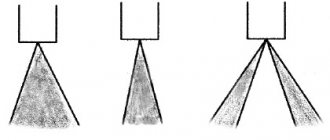
Fuel injectors 1. INJECTOR BODY 2. GUIDE REMOTE BUSHING 3. BUSHING WITH VALVE SEAT 4. VALVE SHUT-OFF 5. INJECTOR TIP 6. SPRAY PLATE 7. SPRAY HOUSING 8. PRU VALVE WIRE 9. SOLENOID HOUSING 10. SOLENOID 11. FUEL INLET FILTER
The MSVT fuel injector is designed to supply fuel to the intake manifold of a separate engine cylinder. The operation of the injector solenoid valve is controlled by the ECU. The nozzle valve of the ball or needle type is made normally closed. The fuel passes through the channels inside the nozzle, through a broken ball or needle valve and is injected into the pipeline through the holes of the spray plate, Fig. Fuel burner. The spray plate has six holes that ensure dosing of the fuel flow and the formation of a conical spray of finely atomized fuel in the nozzle part of the nozzle tip. From the injector tip, fuel enters the intake manifold, where further atomization and evaporation of the fuel occurs before being sucked into the cylinder. An injector with a leaking valve causes a drop in pressure in the fuel system after the engine is turned off. In some cases, this defect manifests itself in difficulty starting the engine (long rotation of the crankshaft with the starter is required). In addition, a small supply of gasoline through a leaky injector valve causes the engine to operate during glow ignition after the ignition switch is turned off.
Fuel pressure regulator 1. VACUUM PIPE 2. O-RING 3. REGULATOR BODY 4. DRAIN PIPE FITTING 5. FITTING O-RING 6. DIAPHRAGM 7. PRESS SPRING 8. VACUUM CAVITY COVER REGULATOR
The fuel pressure regulator includes a pressure reducing valve with a pressure spring and a diaphragm sensing element, fig. Fuel pressure control. The diaphragm separates two cavities of the regulator: fuel and vacuum. The vacuum cavity is connected by a pipeline to the engine intake manifold. The pressure spring of the regulator is also located in the vacuum cavity. The function of the regulator is to maintain a given stable fuel pressure supplied to the injectors and adjust this pressure depending on the engine load. As the vacuum in the intake manifold decreases, the fuel pressure in the system increases. The fuel pressure regulator is installed at the end of the distribution pipe and cannot be repaired in service. When the engine is running, the regulator maintains the fuel pressure in the system in the range of 284–225 kPa. If the pressure goes beyond the lower limit, the normal operation of the engine is disrupted and the ECU sets fault code 44. If the fuel pressure is higher than 325 kPa, a strong smell of exhaust gases appears and fault code 45 is set. Daewoo Nexia fuel and exhaust system repair Next page»»»» »»
- 10. 11. 12. 13. 14. 15. 16. 17. 18. 19. 20. 21. 22. 23. 24. 25. 26. 27. 28. 29. 30. 31. 32. 33. 34.
coming
Reduced pressure in the power system
In the power supply system of an injection engine, the pressure is 300 kPa (3 kgf/cm2), therefore it is prohibited to loosen the connections of the fuel lines while the engine is running or immediately after stopping it. To carry out repair work on the power system on a freshly stopped engine, it is necessary to first reduce the pressure in the power system. 2 - 3 hours after stopping the engine, the pressure in the system will drop to almost zero.
Shift into neutral and apply the parking brake to the vehicle. On the left side of the instrument panel, remove the cover covering the fuse and relay box. Remove the electric fuel pump relay from the block.
Start the engine and let it run until the fuel from the injector rail is completely exhausted. After this, the engine will stall. Turn on the starter for about 3 seconds to equalize the pressure in the pipeline. Install the relay and fuse and relay box cover in the reverse order of removal.
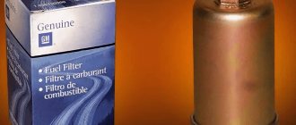
Article number and approximate cost of a branded fuel filter and its analogues
The Daewoo Nexia has a fine fuel filter. It is the same regardless of whether the car engine has 8 valves or 16 valves. The original consumable has one of the following catalog numbers:
- 96130396;
- 25055129;
The cost of a native fine filter ranges from 500 to 750 rubles. Analogs of the branded filter are also available for sale. The best alternatives are shown in the table below.
Table - Analogues of the fine fuel filter for the Daewoo Nexia car
| Company manufacturer | Article number | Estimated cost, ruble |
| Profit | 15302903 | 165-200 |
| Bosch | 0986450119 | 365-410 |
| Parts-Mall | PCC002 | 210-270 |
| Mann-Filter | WK6122 | 550-630 |
| TRW | F185 | 1600-2700 |
In addition to the fine filter, the Daewoo Nexia has a mesh that catches large debris. On cars manufactured before 2002, the filter mesh used has article number 96183953.
A branded coarse filter costs from 160 to 220 rubles. It is also possible to buy analogues from other brands. The table shows the best nets for cars produced before 2002.
Table - Alternatives to native mesh 96183953
| Brand | Article number | Approximate cost, ruble |
| Krauf | KR1048F | 155-200 |
| Market (OEM) | 96183953 | 90-120 |
| Conner | KFPX19 | 110-170 |
| Grog | PZNX1078 | 44-60 |
Daewoo Nexia cars manufactured after 2002 use a mesh filter with catalog number 96350078-2. The cost of a branded mesh ranges from 30 to 80 rubles. The best analogues of filter mesh can be found in the table below.
Table - Analogs of mesh filter 96350078-2
| Company manufacturer | Catalog number | Estimated cost, ruble |
| Krauf | KR1128F | 55-70 |
| Amd | FP164 | 50-70 |
In some cases, instead of replacing the filter mesh, it is more profitable to install a new fuel pump assembly. For Daewoo Nexia cars produced before 2002, a unit with article number 96350078 is required.
The price for consumables varies from 1000 to 1800 rubles. There is also an opportunity to purchase an analogue online. The best alternatives are presented in the table below.
Table - Analogues of the Daewoo Nexia branded fuel cup until 2002
| List of companies | Article number | Approximate price, ruble |
| Profit | 40010035 | 1350-1700 |
| ERA | 775242A | 1650-2200 |
| Onnuri | 96494976 | 1550-1950 |
| Parts-Mall | PDCM001 | 1750-2500 |
| Japan Cars | O20010JC | 950-1400 |
On Daewoo Nexia cars produced after 2002, the fuel filter is 96494976. Its cost varies from 2,700 to 3,000 rubles. The best analogues of the native node are given below.
Table - Analogs of the original fuel module for Daewoo Nexia after 2002
| Manufacturer | Filter article number | Approximate price, ruble |
| Onnuri | 96494976 | 2000-2500 |
| ERA | 775242A | 1650-2000 |
| Profit | 40010035 | 1400-1600 |
| Parts-Mall | PDCM001 | 1800-2300 |
| Asam | 50070 | 1050-1400 |
Mesh
Checking the pressure in the Nexia engine power supply system
The main indicator for determining the health of the engine power system is the fuel pressure in the fuel rail.
If the fuel pressure is insufficient, the following malfunctions may occur:
- unstable engine operation;
- stopping the engine at idle;
- increased or decreased crankshaft speed at idle;
- insufficient acceleration of the car (the engine does not develop full power);
- jerks and dips in engine operation when the car is moving.
First, check the reliability of the electrical contacts in the wiring harness blocks of the injection system units responsible for supplying fuel (fuel pump, injectors). You can only check the fuel pressure in the power system with a pressure gauge with a hose and an adapter for connecting to the fuel rail.
Turn on the ignition and listen - you should hear the sound of the electric fuel pump operating within a few seconds. If the sound of the electric fuel pump is not heard, check the electrical power supply circuit to the pump. (Note: if you turned the ignition on three times without trying to start the engine and once again the electric fuel pump does not start working, this is not a sign of a malfunction. It will turn on simultaneously with the starter starting the engine.) Reduce the pressure in the power system.
Replacing the fine fuel filter
Replacing the fine filter is shown below.
- Relieve pressure in the fuel circuit.
- Clean the fuel filter from external dirt.
Work area to be cleaned
- Unscrew the pipes.
Disconnecting the fuel line
- Loosen the clamp.
Unscrewing the pinch bolt
- Remove the filter.
Pulling out the filter
- Replace the O-rings.
O-rings
- Install a new filter.
New consumables
Installation
- Check for leaks.
Air conditioning Daewoo Nexia
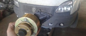
Some Nexia cars were equipped with air conditioning. It was included in the most expensive configurations and worked quite reliably with proper maintenance and operation. The main reasons for the failure of the air conditioner, which relate to electrical equipment, were failures of the electromechanical clutch of the compressor drive and breakdowns of the climate control system. Despite the fairly reliable design of the air conditioner itself, there were annoying errors when assembling components, which sometimes led to premature wear of the compressor and evaporator.
Since the operation of the air conditioner is connected to the heating and blowing system, it could not help but respond to frequent failures of the air circulation drive motor. The engine itself cannot be repaired, but before you say goodbye to it, it’s worth checking the circuit right down to the fuses. If there is voltage on the circuit after the fuse, it is quite possible that the contacts in the motor power supply are to blame.
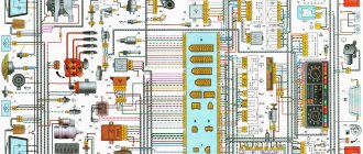
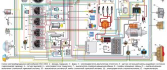
Electrical diagrams of Daewoo Nexia N100 and N150
1. Configuration of electrical connectors and numbering of wire connector sockets for Daewoo Nexia electrical equipment:
2. Diagram of electrical connections of the ignition switch, starter and generator, as well as diagram of Daewoo Nexia connections of ignition system devices:
3. Electrical diagram of Daewoo Nexia - connections of fuel injection system sensors with IEFI-6 type ECU:
4. Electrical connection diagram of the Daewoo Nexia engine malfunction warning light, torque converter lock-up system, fuel pump and on-board diagnostic system with IEFI-6 type ECU:
6. Fuel injection system sensor diagram:
7. Electrical diagram of connections between the Daewoo Nexia engine malfunction warning light, the torque converter lock-up system, the fuel pump and the on-board diagnostic system with an IEFI-S type ECU:
8. Electrical connection diagram for car lighting devices:
9. Electrical diagram of Daewoo Nexia - connections of fog lights and rear fog lights:
10. Daytime running lights, parking lights and license plate lamp and horn electrical connections:
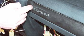
11. Electrical diagrams of the Daewoo Nexia: glove compartment light, cigarette lighter, clock with digital display, interior light and trunk light:
12. Diagram of the car’s brake signal lights, as well as the reversing light and torque converter locking system:
13. Operation of turn signals and hazard warning lights:
14. Electrical connections for heated rear window of Daewoo Nexia:
15. Electrical diagram of Daewoo Nexia - connections of windshield wipers and washers of the windshield and rear window:
16. Instrument cluster:
17. Electrical diagram of the Daewoo Nexia in 3 photos - connections of the electronic control unit with the control system components:
18. Diagram of the Daewoo Nexia cooling system and air conditioner:
Nexia fuse box
As in all European cars of those times, the Nexia has a fuse block with fork-type fuses. This is much more convenient than the old cartridge elements. Each fuse is responsible for a specific section of the circuit. In the event of an overload or short circuit, the fuse does not allow harm to electrical equipment located in the circuit after it. The basic rule, which cannot be neglected, is that any use of jumpers that short-circuit the contacts tightly, or bugs, is unacceptable. It is also unacceptable to use fuses that do not correspond to the rating. If the fuse has a resistance lower than the rated value, it will blow, and if it is significantly higher, it will burn out the equipment that it was supposed to protect.
For ease of use, fuses have housings of different colors. 10 amp fuses have a red body, 20 amp yellow, 30 amp fuses have a green body. The fuse board is located in the same housing as the relay block, and the entire mounting block is located on the driver's side under the instrument panel.