The combustion process of the mixture in a working engine
To better understand the causes of valve burnout, you need to know the basics of gas exchange processes in the engine and their sequence.
- Intake stroke. The intake valves are open, the piston moves down, creating a vacuum zone. At this moment, a mixture of fuel and air is sucked from the intake tract (gasoline engines with distributor injection into the intake or with a monoinjector) or a pure air charge (internal combustion engines of the Diesel cycle and gasoline engines with direct injection).
- Compression stroke. The piston begins to move upward, the intake and exhaust valves close. The mixture compresses, the temperature in the combustion chamber rises.
- Working stroke. A few degrees before the highest dead center (TDC) of the cylinder, the mixture is ignited by a spark (gasoline internal combustion engines) or self-ignites from contact with heated air (diesel engines). Under the influence of the force of expanding gases, the piston rushes down. The reciprocating movement of the piston through the connecting rod and crank mechanism is transmitted to the rotational movement of the crankshaft.
- Release stroke. The exhaust valves open. The piston moving towards TDC pushes the exhaust gases into the exhaust tract.
The phases of valve overlap and inertial filling are omitted intentionally, since they do not significantly affect the consideration of the issue of valve burnout.
Inlet and exhaust valve: what is the difference
The main difference between the intake valve and the exhaust valve is the diameter of the plate: the intake valve has a larger one.
Why? Because the absorption of air from the atmosphere into the cylinder under the influence of vacuum occurs at a lower speed than its expulsion from the cylinder by the piston. It's simple: the amount of air (or air-fuel mixture) is the same, but the speed is different. Accordingly, where the speed is lower, the hole is wider, and the plate covering it is larger in diameter.
All this is true for those valve mechanisms where there are equal numbers of intake and exhaust valves - one or two each. However, there are engines with an odd number of valves: two intake + one exhaust or three intake + two exhaust. Here the opposite is true: the diameter of the exhaust valve plates will be larger than that of the intake valves, because the manufacturer compensated for the low suction speed by adding one “extra” hole, and not by increasing the diameter. You can read more about the relationship between valves and cylinders in the corresponding article.
The second important difference in valve design is their operating temperature. Intake valves operate at 350-500 degrees, but the exhaust valves are harder - hot exhaust gases heat them up to 700-900 degrees. Therefore, accordingly, exhaust valves are often made more heat resistant.
The heads (or discs) of the intake and exhaust valves can be either the same diameter or different. (on cars of outdated brands with small valve overlap) - my approx. Typically the intake valve head is made larger in diameter to improve cylinder filling. For example, the dimensions of the engine valves of the GAZ-53A car: the diameter of the intake valve head is 47 mm, and the exhaust valve is 36 mm. In the KamAZ-740 diesel engine, the diameter of the intake valve plate is 51 mm, and the exhaust valve is 46 mm. Inlet large outlet small.
The device of the poppet valve [edit | edit code]
The poppet valve consists of the actual round disc and a rod of smaller diameter. For reasons of strength and aerodynamics, the transition between the plate and the rod is made with a large radius (Fig. 1). For some time, umbrella (tulip-shaped) plates were popular, reducing the weight of the intake valve to the weight of the exhaust valve (the diameter of the intake valves is chosen larger, since the resistance of the intake tract reduces engine power more strongly than the exhaust resistance) while simultaneously reducing hydraulic resistance. However, this increases the area of the combustion chamber, which increases hydrocarbon emissions.
The valve moves along the axis of the rod, while the plate opens the way for gases, and when seated on the seat, tightly locks it. Some clearance between the valve stem and bushing is necessary to avoid sticking when the valve heats up and to allow the poppet to self-seat onto the seat. To maintain self-installation, and therefore the locking density, the plate has a chamfer at an angle of 45 or 30 degrees to its plane.
Engine valve layout
The number of valves in the engine depends on the adopted gas distribution mechanism. The typical value is 2 or 4 valves per cylinder, but there are schemes with 5 valves (3 of them are intake valves), or even 1 large exhaust valve (direct-flow purge of a 2-stroke diesel engine). Valve springs that support timing kinematics are always spiral with flat ground ends. There are usually 1 (less often 2) springs and 2 crackers per valve. The sizes and shape of the valve cotters are individual; usually each engine has original valve cotters.
The valves can be placed in a bottom-valve or top-valve pattern, located at an angle to each other or in parallel. The purpose of the designer's work when placing them is reliable gas exchange with low aerodynamic resistance, the necessary placement of manifolds in the engine compartment, compactness of the combustion chamber, compliance with exhaust standards, etc.
Features of work
Valves are constantly exposed to high temperatures and pressures. This requires special attention to the design and materials of these parts. This is especially true for the exhaust group, since hot gases escape through them. The exhaust valve plate in gasoline engines can heat up to 800˚С - 900˚С, and in diesel engines 500˚С - 700˚С. The load on the intake plate is several times lower, but it also reaches 300˚C, which is also quite a lot.
That is why heat-resistant metal alloys containing alloying additives are used in their production. Also, exhaust valves often have a hollow stem filled with sodium. This is done for better thermoregulation and cooling of the plate. The sodium inside the rod melts, flows and takes some of the heat from the plate and transfers it to the rod. This way you can avoid overheating of the part.
Engine valve mechanism
Carbon deposits may form on the seat during operation. To avoid this, designs are used that rotate the valve. The seat is a ring made of high-strength steel alloys that is pressed directly onto the seat for tighter contact.
Also, for proper operation of the mechanism, the regulated thermal gap must be observed. High temperatures cause parts to expand, which can cause the valve to malfunction. The gap is set between the camshaft cams and the pushers by selecting special metal washers of a certain thickness or the pushers themselves (cups). If the engine is used, the gap is adjusted automatically.
Too large a thermal gap will prevent the valve from fully opening, and therefore the cylinders will be less efficiently filled with fresh charge. A small gap (or lack thereof) will not allow the valves to close completely, which will lead to their burnout and reduction.
Failure mechanism of exhaust valves during operation
Content
- 1. General information
- 2. Mechanical stress in the exhaust valve
- 3. Exhaust valve seating speed and force
- 4.Technology for the formation of carbon deposits on diesel exhaust valves
- 5. Exhaust valve damage mechanism
- 6. Exhaust valve destruction mechanism process
General information
The exhaust valve is the most important part of a diesel engine and its condition directly affects the reliability of the entire diesel engine. Over the past two decades, diesel power has increased significantly, while fuel quality has decreased significantly due to the use of catalytic cracking. This resulted in greater thermal stress and a more corrosive environment for the exhaust valve, which is the most critical part of the compression chamber. Efforts have been made to reduce exhaust valve failures by making them stronger and more reliable. However, it rarely happens that only one mode is to blame for a failure. Usually several factors are to blame for this.
The strength of the exhaust valve is achieved by replacing the base metal from austenitic steel and with a hard stellite seat to NIMONIC with or without hardfacing. The most common NIMONIC 80A, 81.90. These materials not only have high corrosion resistance (increased strength), but also are less prone to failure.
NIMONIC valves behave better during failures (burnouts) than valves made of austenitic steel. This allows the operator to identify the defective valve and take steps to replace it, without fear of the valve breaking into pieces (pieces) and damaging the diesel engine, as happens with austenitic valves, with which it is difficult to previously detect a breakdown.
Let's consider the operating conditions of the exhaust valve, which has a large surface facing the source of high temperature burning gases, and due to this it heats up very much and this heat is transferred to the valve spindle. Temperature heat is also transferred during exhaust from high temperature, high speed gases flowing around the spindle. To avoid corrosion of the valve bottom and seat, the temperature of the valve bottom should not exceed 450°C. At temperatures above 450°C, the salts of the exhaust gases melt, become liquid, active and corrosive. A decrease in temperature is possible through valve cooling, but this is not done directly, like a valve spindle-seat, which is cooled by water, but does not occur constantly, but cyclically. Some of the heat is removed from the rod through the valve lifter oil, valve guide, and is also cyclically cooled by purge air.
Effective heat removal from the valve bottom and seat depends on the valve seating force and the presence of carbon particles.
The usual temperature of exhaust valves on modern diesel engines is 360-540°C.
On diesel engines with a central exhaust valve, fuel combustion occurs in the center of the cylinder and the temperature distribution in the exhaust valve according to the data is shown in Fig. 3.1 at full diesel power.
The temperature value will be maximum in the center and decrease towards the periphery, towards contact with the seat. To decrease the average temperature, increase the speed of the cooled seat.
Exhaust valve seat life is determined by three factors:
- burnouts on the bottom of the exhaust valve;
- extreme wear of the spindle valve seat;
- wear of the valve spindle stem - wear limits are set by the manufacturer.
The burnout and its size affect the strength of the valve. In the practice of operating diesel engines, it was noted that diesel engines with a central location of the exhaust valve and several injectors are faced with the phenomenon when wear from burnouts occurs earlier than wear from valve grinding, when the diesel engine uses vanadium fuel of the RMK 45 type.
According to the research of senior mechanic E.I. GOLOFASTOV for failures of exhaust valves during the operation of diesel engines - exhaust valves made of austenitic steel with surfacing of the seat with stellite up to 4 mm, the onset of burnout occurs after 450 hours of diesel operation and complete burnout of the exhaust valve occurs after 1100 hours of operation.
Moreover, the burnout wear process is not evenly distributed along the radius of the valve, and the largest burnout size is located at a radius of 60-80% from the center of the valve, as shown in Fig. 3.2.
In Fig. Figure 3.3 shows the temperature distribution of the exhaust valve of a MAN B&W MS type diesel engine at full power load.
Figure 3.3 shows that the maximum valve temperature at a distance of 0.7 valve radius is 513°C. The supposed reason for this phenomenon is the location of the bow-stern nozzles and the fuel jets are directed to the left and right sides.
At this temperature, vanadyl vanadates (5Na20 V20411V2 05 and Na20V205V205) formed by the reaction of alkali and vanadium surrounded by fuel during combustion, melting and spreading along grain boundaries and leading to temperature corrosion.
Mechanical stress in the exhaust valve
When the exhaust valve operates, mechanical stresses arise in it, the source of which is:
- thermal gradient in the valve head;
- landing pressure under the influence of gas pressure;
- seating pressure under the action of spring force;
- residual stresses during the manufacturing process;
- residual distortion of the valve and cylinder.
The presence of voltage in the exhaust valve can be divided into three types:
- low-cyclic voltages;
- high-cyclic stresses;
- residual stresses.
Residual stresses remain during the manufacturing process, especially during the hard-welding process.
Low frequency voltages and low frequency high voltages are caused by a high temperature gradient in the valve head. Voltages arise when starting a diesel engine, stopping it, and when the load quickly increases during start-up. Frequent repetition of such cycles leads to destruction of the exhaust valve. Thus, before increasing the load on the engine, it should run for some time at a low speed, then gradually bring the engine up to full load.
High-cycle voltage, high-frequency low-voltage cycle, which has 1/2 min for a four-stroke diesel engine during commissioning. These stresses occur due to temperature cycling, the impact of the valve on the seat, and the cyclic heating and cooling of valve parts in each cycle.
Temperature changes during loading are small and voltage changes are also small. However, sudden changes in load over a wide range lead to significant changes in high- and low-cyclic stresses, which are the cause of exhaust valve failures.
Exhaust valve seating speed and force
The valve is seated with a force of 500-550 bar; a force of more than 800 bar leads to increased wear. For this reason, the valve material must be strong enough to withstand such forces. The landing speed should be 0.15-0.2 m/sec, this is due to low wear and good valve dynamics. To ensure uniform pressure distribution between the seat and the valve in a cold state, different angles are made on the seat and on the valve. The contact area increases with heating. The landing pressure remains virtually unchanged.
In Fig. 3.4-3.5 shows the contact surface of the exhaust valve and the seat in a cold and hot state.
Technology of carbon formation on diesel exhaust valves
Carbon deposits on the surfaces of the CPG and exhaust valves are formed from fuel contaminants, lubricating oils, and the reaction of carbon deposits with the CPG material. Fuel ash is non-combustible mechanical impurities formed during fuel combustion.
Crude oil contains a number of elements that form the composition of ash, such as: vanadium, sodium, calcium, magnesium, zinc, lead, iron, nickel.
The most corrosive element is vanadium. Since vanadium is contained in fuel in the form of fuel-soluble complex organometallic compounds, its content remains almost unchanged during separation.
Sodium is contained in fuel mostly in the form of NaCI crystals or an aqueous solution of its salts.
The presence of these two elements in the fuel causes high-temperature corrosion on the hottest metal surfaces, such as the surface of exhaust valves in diesel engines.
When the fuel contains vanadium and sodium simultaneously, sodium vanadates are formed with a melting point of approximately 625°C. These substances cause a softening of the oxide layer that normally protects the metal surface, causing destruction of the cylinder boundaries and corrosion damage to most metals. Therefore, the sodium content should be less than 1/3 of the vanadium content.
If the sodium content in the fuel is insignificant, then vanadium pentoxide V2O5 is formed, which acts like vanadate, although it has a higher melting point - about 625 ° C.
Sulfur and alkali contained in the fuel during combustion are oxidized and form sulfur dioxide, sulfur trioxide, soda oxide. These oxides react with each other and the calcium in the lubricating oil to form low melting point salts. Particles of these salts are deposited on the valve plate in a molten state, cooling sufficiently to stick to the valve and not be carried away with the exhaust gases. The temperature at which adhesion occurs is called the joining temperature. In general, these salts consist of sodium sulfate, calcium sulfate, sodium vanadyl, vanadates of various compositions with a wide range of melting points. The most commonly found vanadates are 5Na2OV2O411V2O5, commonly known as 1.1.5NaVV. These vanadyl vadanates melt at a temperature of 540-625°C respectively and therefore the temperature of the outlet valve must be kept below 500°C. However, there is a mixture of salts consisting of 35% vanadium pentoxide and 65% sodium sulfate. This salt melts at 350°C and causes corrosion (valve metal) under normal operating conditions.
However, the exhaust gas temperature cannot be lowered below 350°C when using fuels containing sodium and vanadium in a ratio of 1:3.
Table 3.1 shows an analysis of the salts formed on the surface of the valve and their melting point.
Table 3.1
Analysis of salt content in soot on the valve and their melting point
At temperatures of 350°C and above, carbon salts melt when they reach the melting point - in the molten state, these salts spread along the crystal boundary and, depending on the material, dissolve the protective oxides at the crystal boundary, exposing the crystals to the corrosive action of these melts. This is called intercrystalline corrosion, which causes the exhaust valve surface to burn out.
In Fig. Figure 3.6 shows accelerated intercrystalline corrosion caused by the high temperature of gases flowing through the purged channel.
The area around the channel is only slightly damaged, the appearance of this phenomenon occurred after about 450-460 hours of valve operation, which is in good agreement with the research of senior mechanic E.I. GOLOFASTOV. The same burnout process occurs on the exhaust valve plate.
High temperature corrosion of hardfaced valve material due to purging results in a cobble-like surface. Such a surface is formed as a combination of fatigue cracks formed due to high temperatures and high-temperature corrosion of crack edges leading to transcrystalline corrosion. One of the important factors in controlling vanadium corrosion is to maintain low levels of contaminants, i.e. the amount of pollutants per unit area per unit time.
In operational practice, vanadium corrosion can be controlled by introducing chemicals into fuel additives that react with vanadium during combustion, forming compounds whose melting point is higher than that of vanadium pentoxide or sodium vanadates.
specially developed the chemical VALVECARE to treat and reduce the effect of corrosive deposits that form on seats and exhaust valves, as well as turbocharger parts; — chemical preparation — AMERGIZE; — chemical preparation — COMBUSTION CATALYST.
All of the above chemicals physically modify the ash in the fuel, causing slag and making the ash melting point at normal operating temperatures in diesel. Modified ash particles, hard, small and non-viscous, are emitted in the exhaust gases. The exhaust valve seats become cleaner because... the likelihood of ash compaction is reduced. Compression losses and leaks are minimized, valve and seat life is extended with routine maintenance, and cleaning intervals for both exhaust valves and turbochargers are longer because the ash particles in the gas flow are less viscous.
Maintenance of the exhaust tract is simplified and any ash generated is loosened, easily removed by conventional methods such as brushing.
In Fig. Figure 3.7 shows an exhaust valve that worked without a chemical additive for about 600 hours - burnout and traces of corrosion damage appeared on the valve plate. The same exhaust valve, after cleaning and grinding, worked for the same time, and the control exhaust valve constantly worked on fuel with a chemical additive - the contact surfaces of the valve disc were clean, without signs of burnout or corrosion (see Fig. 3.8).
Another advantage of the above chemicals is the reduction of acidity. Vanadium in fuel acts as a catalyst on sulfur, accelerating the conversion of sulfur dioxide to sulfur trioxide during fuel combustion in a diesel cylinder. The sulfur trioxide then reacts with the gas flow in the exhaust tract, raising the dew point to form sulfuric acid.
All chemicals contain a combination of vanadium and sodium components of ash in a solid, unmolten state, inhibiting salt corrosion.
In Fig. Figure 3.9 shows the exhaust valves of a four-stroke engine, during operation of which a chemical was introduced into the fuel. drug AMERGIZE; in the first version, the exhaust valves ran on fuel without a chemical additive - the presence of ash was visible on the surface of the cylinder cover and on the valves; in another version, the engine ran on fuel with the AMERGIZE chemical additive - there was no ash deposit; Inspection of the valves in the first and second versions was carried out after 3000 hours.
The use of chemicals in fuel changes the nature of fuel combustion in the cylinder, increases the melting point of sodium-vanadium ash and reduces high-temperature corrosion and leaks. Keeps exhaust valves clean for a long time, thereby increasing the service life of exhaust valves and extending the intervals between inspections and cleanings.
Exhaust valve damage mechanism
Factors that lead to damage to the exhaust valve during operation are as follows:
- formation of carbon deposits on the surface;
- cracking and peeling of valve metal;
- vanadium deposits, which can lead to hot corrosion;
- the formation of dents, which lead to the formation of through channels on the sealing surface.
Combustion particulates, scale particles, and AI2O4SiO2 particulates (catalytic particles left in the residual fuel during the cracking process) are pressed into the valve seat and form dents. These dents then concentrate and form through channels; As their operating time increases, the number of cracks increases, regardless of the hardness of the valve material.
Another reason for the formation of dents is the hot hardness of the seat material. A gradual decrease in the hardness of the NIMONIC alloy to 650°C is observed. After which, with a further increase in temperature, the hardness decreases sharply. This decrease in hardness leads to further dent formation.
Dents can also form due to uneven seating of the valve on the seat. Dents appear on a new valve within the first hours of operation. These dents gradually increase in size and then stabilize.
When repairing and lapping the valve, it is not necessary to completely remove dents if they are not through. Burnt areas must be removed by lapping.
Operating practice has shown that valve destruction occurs very rarely due to only one of the above reasons. As a rule, all of the above reasons are to blame for the destruction of the valve.
Exhaust valve destruction mechanism process
Let's consider the mechanism of exhaust valve destruction; To understand this process, we will divide the consideration into three stages.
1st stage. In Fig. Figure 3.11 shows the beginning of the appearance of a dent located on the generatrix of the sealing surface. As a rule, the formation of dents begins in these places.
Normally, dents form and disappear due to wear and tear over a short period of time. However, for such large dents, as shown in Fig., with a diameter of 11 mm and a depth of 0.3-0.4 mm, the time for their disappearance due to wear is much longer. At partial loads, the valve-seat contact surface is smaller than at full load. It can be assumed that there is a gap on some part of the valve-seat sealing surfaces and carbon deposits accumulate in this gap. In this situation, rotating the valve is useless because This gap is always there. With increasing thermal load, carbon deposits, if not completely worn out, begin to form dents near the outermost generatrix of the seat. The formation of a through channel begins from the entrance edge of the dent under partial loads as shown in Fig. 3.11. A thin channel 0.2 mm wide and 0.5 mm deep is formed - a sign of the first stage of destruction of the exhaust valve.
2nd stage. The channel size increases. The progress of increasing channel size depends on the engine load. The thin channel that appears at the first stage allows a certain amount of gas to pass through, depending on the size of the channel. The amount of gas passing through the channel determines the degree to which the temperature of the valve increases. Thus, a small amount of breakthrough gas is not enough to raise the temperature before the corrosive salts begin to melt and the surfaces quickly lose hardness.
These circumstances delay the destruction of the valve up to 500 hours and, thus, during this time normal operating parameters are ensured. During this time, the dimensions of the channel increase and form a channel, as shown in Fig. 3.12.
However, this period can be halved if the diesel engine has been operating on maneuvers for a long time. During the transition period from stage 1 to stage 2 at low loads, you can hear the whistle of gases breaking through the channel. This noise disappears as the load increases and the valve-seat contact increases.
In Fig. 3.12 it can be seen that at low pressures the channel is straight along the contact line; with increasing pressure and seat, the channel becomes wider. However, there are no traces of temperature corrosion, which can occur for two reasons:
- firstly, there may not be enough corrosive salts in the fuel;
- secondly, the temperature near the canal is not high enough.
At this stage there is no increase in temperature and no signs of valve destruction. Only at low speeds can you hear the whistle of escaping gases.
3rd stage. At the third stage, the valve undergoes severe destruction. In Fig. 3.13 and in Fig. Figure 3.14 shows the dimensions of the channel when there is an abnormal increase in temperature and a drop in compression pressure, which is 2-3 bar, because the channel area does not exceed 3% of the total area of the seat. Characters of destruction in Fig. 3.13 and fig. 3.14 have two clear differences in the nature of valve destruction.
In Fig. 3.13 the valve collapsed when the diesel engine was running on fuel with low vanadium and sodium content. This can be seen from the relatively small area along the channel damaged by high-temperature corrosion, despite the high temperature due to the high flow rate of gases. These high-velocity gases made the channel smooth. Dent scales can be observed along the channel, which can be explained by the loss of surface hardness due to the high temperature of the gases.
Valve in fig. 3.14 collapsed during diesel operation on fuel with a high content of vanadium and sodium. This can be seen from intercrystalline corrosion and the rough surface of the channel. The metal surface was corroded by salts and eroded by a high-velocity gas flow, and metal particles were carried away by the gas flow. A large number of scorched spots are observed on the rotating valve leading to the appearance of cracks in the seat as shown in Fig. 3.15. Destruction of the valve in the third stage completely disables the valve and cannot be repaired.
Literature
Diesel exhaust valves. Odessa, 2007 (E.V. KORNILOV, P.V. BOYKO, E.I. GOLOFASTOV, V.P. SMIRNOV)
Similar articles
- Troubleshooting and replacement of piston rings
- Scuffing of parts of the cylinder-piston group
- Centering the movement of trunk and crosshead diesel engines
- Repair of frame, crank and head bearing shells
- Preparation for the annual survey of the vessel by the classification society
- Hydraulic system operation
- Design of the hydraulic drive system for opening the exhaust valve of MAN B&W diesel engines type MC
- Design of the exhaust valve of MAN B&W diesel engines type MC
- Disassembly and inspection of the exhaust valve
- Design of the mechanical drive of the K98GG diesel exhaust valve
4.5 Rating 4.50 (1 Vote)
Valve mechanism design
A conventional engine requires a minimum of two valves per cylinder to operate. One inlet and one outlet. The valve itself consists of a rod and a plate (head). I call the place where the plate comes into contact with the cylinder head the saddle. Intake valves have a larger poppet diameter than exhaust valves. This ensures better filling of the combustion chamber with the air-fuel mixture.
Valve mechanism design
The entire valve mechanism consists of the following main elements:
- intake and exhaust valves;
- guide bushings (provide precise direction of valve movement);
- spring (returns the valve to its original position);
- valve seat (point of contact between the disc and the body);
- crackers (two crackers provide a supporting surface for the spring and fix the entire structure);
- valve stem seals or oil flinger rings (prevents oil from entering the cylinder);
- pusher (transmits pressure from the camshaft cam).
Cams on the camshaft press on the valves. Their return to their original position is ensured by a spring. The spring is attached to the rod using crackers and a spring plate. To dampen resonant vibrations, not one, but two springs with versatile winding can be installed on the rod.
Valve guides
The guide bushing is a cylindrical part. It reduces friction and ensures smooth and correct movement of the rod. During operation, these parts are also subject to stress and temperature. Therefore, wear-resistant and heat-resistant alloys are used for its manufacture. The exhaust and intake valve bushings are slightly different from each other due to the difference in loads.
Materials for valve production
For the manufacture of intake valves, chromium steel is used, which is resistant to corrosion in gas environments at temperatures above 550 °C. This type of steel is quite fragile.
The intake and exhaust valves of automobile engines are poppet-shaped. The valve is opened by a valve mechanism controlled by an eccentric cam. The operation of the cam is synchronized with the position of the piston and the period of rotation of the crankshaft.
As a result, they are made from more durable materials than intake valves and are therefore more expensive.
The valve guide is located coaxially with the valve seat so that a sealed gas-tight contact is ensured between the operating face of the valve and the seat. The valve operating chamfer and seat are beveled at an angle of 30° or 45°. These are the nominal chamfer angle values. Actual values may differ by one or two degrees from nominal values. The valves and valve seats used in most engines have a nominal bevel angle of 45°. The valve is pressed against the seat under the action of a spring. The spring is held on the valve stem (some auto mechanics call it the valve stem) by a spring support plate, which, in turn, is locked on the valve stem by a lock (cottons). To dismantle the valve, it is necessary to compress the spring and remove the crackers. After this, you can remove the spring, cuff, and remove the valve from the head.
Valve group operation:
3.1. Synchronization mechanism:
The synchronization mechanism is kinematically connected to the crankshaft, moving synchronously with it. The timing belt opens and seals the inlet and outlet ports of individual cylinders in a conventional operating order. This is how the process of gas exchange occurs in the cylinders.
3.2 Timing drive operation:
The timing drive depends on the location of the camshaft.• With a lower shaft - through cylindrical gears are made with inclined teeth for smoother operation, and for silent operation the gear ring is made of textolite. A parasitic gear or chain is used to provide drive over a longer distance.• Top shaft - roller chain. Relatively low noise level, simple design, low weight, but the circuit wears out and stretches. Through a neoprene backed timing belt, reinforced with steel wire and covered with a wear-resistant nylon layer. Simple design, silent operation.
3.3. Gas distribution diagram:
The total flow area provided for the passage of gases through the valve depends on the duration of its opening. As is known, in four-stroke engines, to implement the intake and exhaust strokes, one piston stroke is provided, corresponding to a rotation of the crankshaft by 180˚. However, experience has shown that for better filling and cleaning of the cylinder, it is necessary that the duration of the filling and emptying processes be longer than the corresponding piston strokes, i.e. the opening and closing of the valves should not be done at the dead points of the piston stroke, but with some overtaking or delay.
The opening and closing moments of the valves are expressed in crankshaft rotation angles and are called valve timing. For greater reliability, these phases are made in the form of circular diagrams (Fig. 1). The suction valve usually opens with an overrunning angle φ1 = 5˚ - 30˚ before the piston reaches top dead center. This ensures a defined valve cross-section at the very beginning of the filling stroke and thus improves the filling of the cylinder. The suction valve is closed with a delay angle φ2 = 30˚ - 90˚ after the piston passes the bottom dead center. Delaying the closing of the intake valve allows you to use the speed of the intake fresh fuel mixture to improve refueling and, therefore, increase engine power. The opening of the exhaust valve is carried out with an overtaking angle φ3 = 40˚ - 80˚, i.e. at the end of the stroke, when the pressure in the cylinder gases is relatively high (0.4 - 0.5 MPa). Intensive release of a gas cylinder, started at this pressure, leads to a rapid drop in pressure and temperature, which significantly reduces the work of displacing working gases. The exhaust valve closes with a delay angle φ4 = 5˚ - 45˚. This delay ensures good cleaning of the combustion chamber from exhaust gases.
General timing valve structure
All the main timing components have already been identified; let’s collect this information together. So, the key components of the gas distribution mechanism, starting from the crankshaft:
- a drive that provides a mechanical connection between the crankshaft and the associated camshaft (sometimes there are several of them);
- camshaft (sometimes a series of shafts, depending entirely on the layout of the internal combustion engine and the total number of valves);
- valve group (consists of valves (one or more intake and also exhaust), often special devices that ensure interaction directly with the camshaft; direct connection between the camshaft and the group of intake and exhaust valves is almost never used, only through intermediate mechanisms);
- housing (this is the part of the engine where the camshaft (several shafts) are located, as well as the timing valve group, components of other systems, for example, lubrication).
In addition, modern engines and their timing belts are usually equipped with additional components. That is, they are present on some power units, but not on others, and are not mandatory. There are many such components; let’s name those that occur almost always or very often. These are, first of all, camshaft position sensors (DPRV, they are also Hall sensors, they determine the angular position of the gas distribution mechanism, they are installed if the engine is equipped with an ECU, an electronic control unit, of modern engines 99.9% are such). In addition, components of different systems can be installed. For example, there are systems that provide variable valve timing, others turn off the cylinders. Let's also highlight devices that regulate the thermal clearances of valves, now these are hydraulic compensators (sometimes hydraulic supports), others were previously used.
It should be understood that these are the main options; it is almost impossible to cover everything within one article; different design solutions are used, even within the same scheme. That is, it is better to consider each individual engine separately. Let's talk about all the components in general.
How to diagnose valve burnout without dismantling the cylinder head
In principle, the procedure for determining valve burnout without resorting to removing the cylinder head was described above.
Note that for engines that require periodic adjustment of the valve mechanism, failure to do so in a timely manner also risks burning out the valves. Modern power units are equipped with an automatic thermal clearance adjustment system, however, even in this case, any problems associated with the operation of hydraulic compensators can also lead to partial deformation of the valve surface.
Please note that when carrying out the adjustment procedure, valves that are too clamped can have more serious consequences than valves that are not tightened enough. In particular, this leads to premature wear of the rod and guide bushing. And this is a deformation of the mechanism, a change in its geometry with all the ensuing consequences, which we will talk about later.
The same troubles can arise from running a CPG on a lean mixture. Engines with installed gas equipment suffer especially in this case, and this is a recent trend associated with the high cost of gasoline compared to liquefied gas.
Most often, motorists, having measured the compression level and determined that it does not meet the standard indicators, rush to diagnose the malfunction in order to clarify the diagnosis, grabbing a set of keys and starting to dismantle the BC head. In principle, there is nothing reprehensible in this, since eliminating the malfunction still risks disassembling the power unit.
But there is a way to determine the cause of deterioration in engine performance without disassembling it. And if you know in advance why the motor started to fail, you will fix the problem faster. The method itself is quite simple and requires minimal knowledge of motor design.
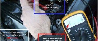
So, the verification procedure is as follows:
- start the engine and let it reach operating mode;
- disconnect the breather hose and observe the results;
- if warm air is simply blowing from the hole without smoke or with minimal, almost invisible smoke, then the problem is that the valves are burnt out;
- in cases where clearly visible smoke of a dense consistency with a gray tint comes out of the hole, and with a pronounced exhaust smell, we are dealing with problems with the piston group. Most likely - due to the occurrence of rings or burnout of the piston itself;
- Next, without regard to the presence/absence of smoke, we unscrew the spark plug from the cylinder identified as problematic. If the piston group is damaged, it will be oily; if it is dry, then this is another argument in favor of problems with the valve mechanism.
If you determine that a certain valve has burned out, you can rest assured that the condition of others is also not ideal. You can verify this by disassembling the cylinder head. But if the condition of the other valves is normal, you can only change the burnt one, but with the obligatory replacement of all valve stem seals. And, of course, we should not forget about grinding in the new valve.
Adjusting engine valves.
The need for adjustment is determined primarily according to the maintenance and repair schedule established by the manufacturer. This information is contained in the manuals for this car and engine. There is a need for adjustment in the event of unscheduled repairs and other convenient occasions.
The thermal gap must be checked if the following violations are detected: decrease in power, presence of extraneous noise (rustling, ringing), low compression, increased fuel or oil consumption, shooting in the muffler or intake manifold, check signal indicates a rich, lean mixture, deviation in the condition of the spark plugs . Either one of these symptoms, or a combination of several, may indicate a malfunction in the gas distribution mechanism or other components.
????Why chip a car?
For obvious reasons, many drivers are in no hurry to upgrade their cars in this way, fearing the consequences. To decide whether the “game is worth the candle,” let’s consider all the pros and cons. So, the advantages of chipping the “brains” of a car:
- Saving. Chip tuning will cost the driver much less than mechanical changes in the engine design or intake-exhaust system.
- Improved performance. Companies that reconfigure the engine control unit promise their clients various benefits: increased engine power, reduced fuel consumption and reduced noise.
- Flexibility of customization. From several firmware options, the vehicle owner is offered to choose the most optimal one for his specific needs.
- Reversibility of the process. If we talk about mechanical modernization, then, in this case, a specialist cuts the combustion chambers, increasing their volume. Chip tuning looks safer against this background, as it allows you to roll back to factory settings at any time.
These are the advantages that a specialized service center will certainly tell you about. However, it is worth remembering the associated risks. Let's look at them a little later.
How to adjust valves
All procedures must be carried out only on a cold engine. This is done to ensure that the setup results remain standard: this is exactly what they do at the manufacturing plants. It is worth noting that the procedure for adjusting the valves on each car is different: you can find it out from the instructions for the car or the relevant literature. The process is carried out by screwing in or unscrewing special adjusting screws, or by selecting flat washers. Each of these options is considered separately.
Using special tools
Engine valves are adjusted using a set of feeler gauges or a special rack and indicator. Both methods are quite widespread: the first is simple, accessible and requires minimal financial and time costs. To apply the second method, you will have to buy a device and a special device.
Adjustment using feeler gauge and locknuts
This method of setting the timing belt is typical for Russian rear-wheel drive cars (“classics”). Algorithm of actions:
- Remove the air filter housing and disconnect all tubes, cables and levers from the valve cover. To make it easier to turn the engine crankshaft, remove the spark plugs.
- Remove the valve cover and the front timing belt cover (if there is one, it may also be a chain).
- Set the piston of the cylinder from which the procedure will begin (for example, in the Zhiguli “classic” it is the 4th) to the top dead center position: the valves will be in the closed position.
- Observing the indentation mark on the engine shaft pulley, rotate it until it coincides with the mark on the lower front cover of the BC. The recessed point on the timing shaft sprocket should also coincide with the mark on its “bed” (housing).
- Use an open-end wrench to hold the adjusting hardware and at the same time loosen the locknut. Next, you need to use a set of feeler gauges to adjust the valves. Select the thin plate you need and insert it between the rocker arm and the valve stem. When adjusted normally, the feeler gauge will pass through with little friction. The gap value must be adjusted according to the table, which is different for each car (for VAZ2101-07 - 0.15 mm). Now tighten the locknut and check the clearance again. Repeat the operation if necessary. Follow the order of valve adjustment: for example, for a VAZ classic: 8-6, 4-7, 1-3, 5-2.
Adjustment using washers
This type of timing adjustment is more typical for front-wheel drive cars. To produce it, you need:
- Remove the valve cover.
- Find the marks on the engine block, timing belt pulley and, turning the crankshaft clockwise, make sure they match. As a result, the first piston will be in the TDC position.
- Determine the gap between the shim and the camshaft cam (they are the first when viewed from the pulley side).
- If there is a larger or smaller gap, select another washer (each has a corresponding marking; if not, use a caliper, or better yet, a micrometer).
- After installing the washer, check the gap again: the permissible deviation is no more than 0.05 mm in both directions.
- Do not forget that the gap size for the intake and exhaust valves is different - this parameter must be found out from the operating instructions for a particular car.
Adjustment using indicator and rack
This method is considered more accurate and was especially popular during the USSR. This adjustment method is good for engines that have been in operation for a long time, since the device and measuring rod take into account the wear on the surfaces of the parts. Progress of the procedure:
- Remove the valve cover, having first disconnected the levers and cables from it.
- Rotate the engine shaft until the marks match, just as when adjusting the valves using a feeler gauge.
- Take the rack and fix it on the cylinder head (fastening is carried out to the studs of the camshaft housing). There is a small nuance: you do not need to completely screw in all 3 nuts securing the rack, otherwise it will dangle. First of all, tighten the outer hardware, then begin to unscrew the middle bolt until the rail becomes motionless.
- Take the dial indicator and secure it to the rail, and place the device’s foot on the edge of the valve cam.
- Using the included grip, grab the cam and pull it up: the indicator needle should pass 52 divisions (at an air temperature of +20 degrees). If this is not the case, then you need to adjust the valve using one of the two methods described above.
How to determine a burnt valve without removing the cylinder head
Inspection of valves using an endoscope connected to a smartphone
There are two main ways to determine a burnt-out valve with high accuracy without disassembling the engine:
To understand that the valves have burned out, you can carry out these operations yourself or contact a car repair shop. A budget endoscope, like a compression meter, will cost 500–1000 rubles. The mechanics at the service station will charge about the same for diagnostics. Inspection with an endoscope connected to a smartphone, tablet or laptop allows you to get a good look at the damaged valve, and a “compressometer” will show the pressure drop in the cylinder.
Before checking a burnt valve, you need to make sure there are no problems with clearances. They must be set correctly, because a pinched valve that is still intact and cannot close completely behaves in the same way as a valve that has already burned out.
How to find a bad cylinder
You can determine a cylinder with a burnt-out valve by measuring compression or removing wires/coils from spark plugs with the engine running. How to check a burnt valve on a gasoline engine by sound:
Determination of a cylinder with a burnt-out valve
If the cylinder maintains pressure properly, then when it is turned off, the engine begins to work worse, trip and shake, and when connected, operation returns to normal. But if the valve burns out, the cylinder does not fully participate in the work, so the sound and vibration of the motor do not change after disconnecting and connecting the spark plug.
For diesel engines, only the option with a compression gauge is available due to the lack of spark plugs. In a cylinder with a defective valve, the pressure will be approximately 3 (or more) atm less than in the rest .
How to determine what the problem is
Since you can definitely recognize a burnt valve with an endoscope, it is better to choose this option if possible. For inspection you need:
Burnt valve in the endoscope picture
Testing with a compression gauge is based on understanding what happens to the pressure when a valve burns out. For a heated gasoline internal combustion engine, normal compression is 10–15 bar or atmospheres (1–1.5 MPa), depending on the compression ratio. The pressure in a diesel cylinder is 20–30 bar or atm. (2–3 MPa) , therefore, to check it you need a device with a pressure gauge that has a wider measurement range.
How to determine that a valve has burned out using a pressure gauge is indicated in the instructions below. If the tip of the compression gauge is equipped with a rubber cone rather than a thread, an assistant will be required.
The procedure for checking burnt-out valves with a compression meter:
Gasoline “compression gauge” with thread and conical nozzles
Diesel “compression meter” with a measurement scale of up to 70 bar
After taking compression measurements, compare the instrument readings for each cylinder. Normal values for different internal combustion engines are indicated above; the spread across cylinders should be within 1 bar or atm. (0.1 MPa). A sign of burnout is a significant (3 atm or more) drop in pressure.
A burnt out valve is not always the culprit for low pressure. Poor compression can be caused by stuck, worn or broken rings, excessive cylinder wall wear, or piston damage. You can understand that a burnt valve behaves this way by injecting about 10 ml of engine oil into the cylinder and re-measuring the compression. If it has increased, there is a problem with the rings or cylinder wear; if it has not changed, the valve does not hold pressure due to burnout.
Is it possible to drive with burnt out valves?
For those who, based on symptoms, have determined that their car has problems with the valves and are wondering: is it possible to drive if the valve is burnt out? – the immediate answer is: it is extremely undesirable, it can lead to additional costs. If the valve really burns out, the consequences can be disastrous for the engine:
What to do if engine valves are knocking
The easiest and fastest way is to have it repaired by professionals. However, not everyone can afford to pay for their services. Therefore, you have to figure it out and solve the issue yourself. There are motorists who are interested in repairing their car with their own hands. There are also people who accumulate experience in self-repair for some purpose.
If valve knocking is a problem in your car and you have to repair it yourself, be prepared to do some serious work. Seriously and carefully, because if you make a mistake, the sound will only become stronger. Therefore, it is not recommended for a novice motorist to eliminate valve knocking. The sequence of actions is of great importance in this type of repair. First of all, it is recommended to study the repair manual for a specific car brand. Next you need to follow the algorithm:
- Engine oil is drained.
- The cylinder head plug is unscrewed. This will clear the way to the valves.
- The camshaft must be rotated until the mark on the pulley and the unit match.
- Determine the gap between the rods and valves by touch. The size of the gap can be changed using an adjusting washer.
- Depending on the specific car model, you need to turn the washer the required number of revolutions.
- Reassemble everything in reverse order and then check if the valve knocking has gone away.
Each car model has its own operating characteristics. But on average, every 25 thousand kilometers you need to adjust the valve clearances. The number of valves directly affects the noise level when they knock. The more valves, the louder the noise will be in the event of a malfunction. There is an engineering solution to the problem - some cars use hydraulic pushers to accurately maintain valve clearances.
Timing valves require preventive maintenance. It consists of periodically cleaning their surface from the deposits that have formed. Carbon deposits can reach a thickness that makes it difficult for the valves to operate properly. Therefore, you should not forget about their periodic cleaning and grinding. Careful implementation of preventive maintenance will extend the life of the engine and even slightly reduce fuel consumption.
If self-adjustment of the valves does not give a positive result, then it is better to contact a professional service station. Setting the gap yourself in this case is hardly possible. Sometimes the cause of valve knocking is completely different faults. But it is also possible that the valve clearances are set incorrectly.
Gas distribution mechanism
In modern engines, the gas distribution mechanism is located in the engine. It consists of the following main elements:
- Camshaft.
This is a complex part, which is made of durable steel or cast iron with high precision processing. Depending on the design of the timing belt, the camshaft can be installed in the cylinder head or in the engine crankcase (this arrangement is not currently used). This is the main part that is responsible for the sequential opening and closing of the valves. The shaft has support journals and cams, which push the valve stem or rocker arm. The shape of the cam has a strictly defined geometry, since the duration and degree of opening of the valve depends on this. The cams are also multi-directional to ensure alternating operation of the cylinders. - Drive unit. Torque from the crankshaft is transmitted through the drive to the camshaft. The drive varies depending on the design solution. The crankshaft gear is half the size of the camshaft gear. Thus, the crankshaft rotates twice as fast. Depending on the type of drive, it includes:
- chain or belt;
- shaft gears;
- tensioner (tension roller);
- damper and shoe.
- Inlet and exhaust valves. They are located in the cylinder head and are rods with a flat head at one end called a poppet. Intake and exhaust valves differ in design. The intake is made in one piece. It also has a larger diameter plate to ensure better filling of the cylinder with fresh charge. The outlet is often made of heat-resistant steel and has a hollow core for better cooling as it is exposed to higher temperatures during operation. Inside the cavity there is a sodium filler, which melts easily and removes some of the heat from the plate to the rod.
The valve plates have special chamfers that provide a tighter fit to the holes in the cylinder head. This place is called the saddle. In addition to the valves themselves, the mechanism contains additional elements that ensure its proper operation:- Springs. Return the valves to their original position after pressing.
Valve stem seals. They are special seals that prevent oil from entering the combustion chamber along the valve stem.
- Guide bushing. Installed in the cylinder head housing and ensures precise valve movement.
- Crackers. With their help, the spring is attached to the valve stem.
- Pushers. Through the pushers, the force is transmitted from the camshaft cam to the rod. Made from high strength steel. They come in different types (mechanical (glasses), roller, hydraulic compensators). The thermal gap between the mechanical pushers and the camshaft cams is adjusted manually. Hydraulic compensators or hydraulic pushers automatically maintain the required thermal gap and do not require adjustment.
- Rocker arm or levers. A simple rocker is a two-arm lever that performs a rocking motion. Rocker arms may perform differently in different configurations.
- Variable valve timing systems. These systems are not installed on all engines. You can read more about the device and operating principle in a separate article on our website.
Typical intake valve failures
Of course, the most common failure of valves is their bending as a result of a broken timing belt. The same thing can happen without a break if the belt was replaced by a non-professional who mistakenly placed marks on the crankshaft and camshaft (or camshafts) pulleys. Breaks are especially dangerous for modern complex engines equipped with variable valve timing and other high-tech systems.
Another common malfunction of the valve mechanism is the overgrowing of the intake and exhaust valves with carbon deposits. As a rule, the problem can be identified at a fairly early stage by a decrease in power and popping noises in the intake and exhaust pipes, a metallic knock in the cylinder head and a drop in engine power.
Carbon deposits on seats and valves prevent them from sealing tightly and reduce compression. As a result, engine power also decreases. Broken springs can cause the valve to not fit tightly against the seat and lead to deformation of the cylinder head, pitting, or sticking of the stem. A large thermal gap between the lever and the valve stem also leads to a sharp metallic knock and a drop in engine power.
Work order
Now the sequence of actions:
- We install the VAZ 2114 on a flat surface, the engine must cool completely so that there is no error in the measurements due to metal expansion;
- Remove the valve cover, as well as the side cover under which the timing belt is located. The surface under the lid must be wiped of oil. You should also carefully inspect the timing shaft for burrs, holes, and signs of significant wear. If there are any, the shaft will have to be replaced;
- We unscrew the spark plugs to make it much easier to turn the crankshaft in the future.
- We combine the mark on the camshaft drive gear with the protrusion on the cylinder head, that is, we set the TDC on the first cylinder. This can be done using a wrench, which we use to rotate the crankshaft by the pulley bolt. But some car enthusiasts do things a little differently - jack up the front wheel on the left and engage 4th gear. Then they simply rotate the wheel, and since the gear is engaged, this rotation will be transmitted through the transmission to the engine;
- After aligning the marks on the camshaft gear, strictly opposite the existing mark, we make another one with chalk. This will make future work somewhat easier.
- We use a feeler gauge to measure the gaps on valves 1 and 3 (you need to count from the camshaft gear. The 1st is exhaust, and the 3rd is intake);
- The gap on 1 valve should be 0.35 mm, but an error is allowed. That is, we take a feeler gauge 0.35 mm thick and insert it between the shaft cam and the adjusting washer. If the probe moves with little effort, then the gap is normal, but if the probe does not enter or is very loose, then adjustment is required. We do the same check on valve 3, but the gap on it should be 0.2 mm.
- The adjustment of the valves is carried out as follows: we attach the device for pressing the valves to the studs securing the cover. This device has a curved lever that we place between the cam and the washer. Using the handle of the device, we press on this lever, as a result of which it will press on the pusher. This device comes with a special clamp, which we place between the camshaft and the pusher. After releasing the handle, the latch will hold the valve in a squeezed state, while the washer will not be pinched and can be removed with tweezers.
- Let's look at an example of what kind of washer will need to be installed in order for the gap to be correct. For example, when checking the exhaust valve, it was found that it was not 0.35 mm, but 0.42 mm, that is, it was increased by 0.07 mm. Next, remove the washer that was installed. There should be a mark on it indicating its thickness (for example, 3.65 mm); if there is no such mark, then you will have to measure the thickness with a micrometer. Now we add to the thickness of the washer the value by which the gap is increased, in our case - 0.07 mm, as a result we get the value of the thickness of the washer for installation - 3.65 + 0.07 = 3.72 mm. But since a washer with such a thickness is not included in the kit, we install a new washer with a thickness as close as possible to the obtained value, that is, 3.7 mm. This is why an error of 0.05 mm is allowed.
- We install the washer of the required thickness in place with the size mark down (towards the pusher). Next, use the lever of the device to press the valve again and pull out the latch. This completes the adjustment.
- Next, the remaining valves are adjusted, but for this you need to know the order. After checking valves 1 and 3, turn the camshaft half a turn (for ease of installation, we made a mark on the gear in advance) and check valves 2 (intake) and 5 (exhaust). Then we turn it another half turn and adjust 6 (intake) and 8 (exhaust). To check the 4th (intake) and 7th (exhaust) valves, you still need to turn the camshaft half a turn once.