If your car has any malfunction related to electrical equipment, then, first of all, you should start checking the fuse box (hereinafter referred to as the fuse box). This material will help you find out where the Nissan Almera Classic fuses are located, what they are responsible for and how to properly check and replace them.
Location and electrical diagram
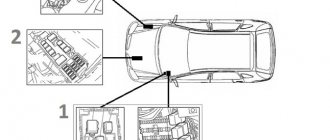
In the Nissan Almera classic n16 there are several fuse blocks responsible for the operation of electrical equipment.
One of them is located in the car interior, the other two are in the engine compartment. On the front side of the power supply unit, located in the vehicle interior, there are several fuses (hereinafter referred to as fuses) and relays.
On the other side of the device there are three more main relays.
There are two power supplies in the engine compartment. One of them contains relays, and the other contains only fusible devices. Below are diagrams of all three blocks, as well as a description of the fuses in them.
PSU in the cabin
What are these elements responsible for? Below is a table with the designation of each PP.
You may also have noticed several relays whose purpose is not described in the table. They should be highlighted separately, since the relays are designed for more powerful voltage consumers.
| Number | Purpose |
| R1 | This component ensures the functionality of the headlight lamps, that is, it is responsible for both low and high beam. |
| R2 | The second component by number ensures the functioning of the throttle valve. If it fails, the operation of the car will be incorrect or impossible. |
| R3 | Responsible for the operation of electric windows. |
| R4 | Ensures the functionality of the rear fog lamps. |
As for the device number 22, which is responsible for the functionality of the cigarette lighter. In Nissan Almera classic n16 models, cigarette lighter failure is a common problem. It can even be called a disease, since many motorists encounter this malfunction.
If you notice that the cigarette lighter is not working, first check the functionality of the fuse. Perhaps that is where the problem lies.
However, many car owners use their cigarette lighter as a power source for various electrical consumers.
In particular, these can be video recorders, special air fresheners, DVD players and laptops.
Of course, even with a voltage converter, the cigarette lighter is simply not able to cope with such a task. So if it is the PP that fails, then you can consider yourself lucky. Otherwise, you will have to change the cigarette lighter, even worse if this causes the mounting block itself to burn out.
As you remember, at the beginning of the article we mentioned that there are also several relays on the back of the power supply, which is located inside the car. If the block is completely dismantled, the relays will look approximately as shown in the photo.
| Number | Purpose |
| R1 | Ensures the functioning of the ignition coil. If it fails, starting the engine will be impossible. |
| R2 | Responsible for the operation of the engine supercharger. |
| R3 | This device ensures the operation of additional voltage feeders, that is, in fact, all electrical accessories. |
PSU in the engine compartment
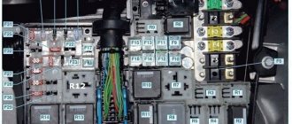
- First, let's look at the diagram and description of the power supply with fusible devices, which is located in the engine compartment between the battery and the engine.
Diagram of the power supply located in the engine compartment, between the battery and the internal combustion engine
Description of the components of the power supply installed in the engine compartment, between the battery and the engine- Next, we will describe the diagram of the mounting block with the relay, which is installed in the same place, in the engine compartment, only to the left of the engine, if you stand facing the hood.
| Number | Purpose |
| R1 | Responsible for the operation of the third radiator fan relay of the cooling system. |
| R2 | Without this element, the operation of the front fog lamps will be impossible. |
| R3 | This component is responsible for the operation of the air conditioner. |
| R4 | Steering wheel signal relay. |
| R5 | Also ensures the functionality of the radiator fan. |
| R6 | Responsible for the operation of all headlights and lights in the vehicle interior. |
| R7 | The operation of the starter depends on this relay. |
Block in the Almera classic interior
It is located in the instrument panel on the left side, behind a small box.
Scheme
Description
| 1 | 15A Electric heater motor |
| 2 | 15A Electric heater motor |
| 3 | Reserve |
| 4 | 10A Direction indicators |
| 5 | 10A Instrument cluster and reversing lights |
| 6 | 10A Anti-lock brake system |
| 7 | 20A Windshield wipers |
| 8 | 10A Heated front seats |
| 9 | 15A Fuel pump |
| 10 | 10A Additional consumers |
| 11 | 20A Heated rear window |
| 12 | Reserve |
| 13 | 10A Headlights |
| 14 | 10A Fuel injection nozzles |
| 15 | 10A Instrument cluster, clock |
| 16 | 15A Cigarette lighter |
| 17 | 10A External rear view mirrors |
| 18 | 10A Interior lamp |
| 19 | 15A Door locks |
| 20 | 10A Brake lights |
| 21 | 10A Car Radio |
| 22 | 10A Engine control system |
| 23 | 10A Airbags |
| 24 | 10A Air conditioner |
| 25 | 10A Automatic transmission control system |
| 26 | 10A Ignition system |
The cigarette lighter is controlled by fuse number 16 at 15A.
Face Relay
- power window relay;
- rear fog lamp relay;
- central locking relay
Rear side relay
- air conditioning relay;
- 1st ignition relay;
- 2nd ignition relay;
- accessory relay.
Fuses and relays in Nissan Almera N16
In total, the car has 2 fuse blocks and 1 relay block. These diagrams and location are only suitable for the body - N16 production from 2000, 2001, 2002, 2003, 2004, 2005 and 2006.
- 0:280
- 1:785
The cabin unit includes several fuses and relays. On the reverse side of this block there are 3 more important relays. The remaining two are located under the hood. One contains only relays, the other only fuses. The diagram and tables provide a precise description of all blocks. Location of blocks and decoding of their fuses.
- 1:1413
- 1. Fuse box in the cabin
- 1:1477
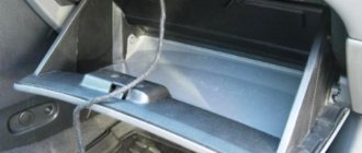
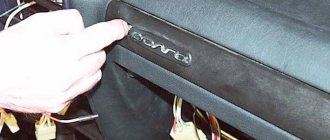
To access it, open the driver's door, in the lower panel on the left, open the mini glove compartment, also known as the cover of the unit. We take out the entire pocket from the panel.
- 1:1760
- 2:2265
- 3:504
- Photos of blocks from different cars to compare the positions of the fuses.
- 3:647
- 4:1152
- 5:1657
- Scheme of the first block with numbering for the table below
- 5:1752
1 - 10A Mirrors 2 - 10A Brake light bulbs 3 - 15A Electrical socket 4 - 7.5A For additional electrics 5 - 000 Hazard alarms and turn signals 6 - 10A For additional electrics 7 - 20A Heated rear window 8 - 10A Oxygen sensor 9 - 10A Additional electrical package 10 - 10A Electrical package 11 - 10A Automatic transmission controller 12 - 10A Electrical package (i.e. all control of all turn signals, backlight and main power supply for the dashboard, illumination of the panel where the stove is) 13 - 10A Interior lamp 14 - 15A Interior fan electric motor (heater /air conditioner) 15 - 10A Air conditioning 16 - 15A Interior fan electric motor (heater/air conditioner 17 - 10A Fuel injection system 18 - 10A Airbags 19 - 20A Additional electrical accessories 20 - 10A Engine controller 21 - 10A Start signal 22 - 15A Cigarette lighter 23 - - - Not used 24 - 20A Additional electrical package 25 - 20A Windshield wiper 26 - 7.5A For additional electrics 27 - 15A Front and/or rear window washer (on the steering column switch) 28 - 15A Rear window washer 29 - 15A Fuel pump 30 - 10A Speedometer, tachometer, temperature and fuel level indicators 31 - 10A ABS 32 - 10A Reserve 33 - 15A Reserve 34 - 20A Reserve
- 5:4018
- Relay
- 5:13
- R1 Headlight relay R2 Throttle control relay R3 Power window relay R4 Rear fog light relay
- 5:259
- On the back of the cabin unit, if you pull it out completely, there will be a plate with 3 relays.
- 5:431
- 6:936
- Photo and diagram of the additional plate
- 6:1008
- R1 Ignition relay R2 Supercharger motor relay R3 Additional equipment relay (electrical accessories)
- 6:1211
- 2. Fuse box in the engine compartment
- 6:1292
Recommendations for diagnosing electrical equipment
The main causes of malfunctions in the operation of car electrics: contact failures in circuits, oxidation of terminals on connectors, failure of relays and blown fuses or fuse links. Symptoms of violations can be different - from short circuits due to insulation damage to the shutdown of devices, components (one or several at once) and failure to start the engine. Serious problems in an electrical circuit with powerful consumers can cause the wiring to ignite and lead to a fire, so when even minor faults are detected, it is important to diagnose the entire electrical circuit.
The search for the cause of the malfunction begins with the identification of working elements by the method of exclusion until the detection of a non-working unit (relay or blown fuse). If several consumers do not work, then contact to ground may be broken, since they can all be connected through one circuit.
To identify problems in circuits, special diagnostic equipment is used: a voltmeter, a tester, a set of connecting wires with alligator clip terminals, or a probe with an indicator and a 12 V test light. Before checking, carefully study the circuit and test for the presence of voltage, starting from the source power supply to the fuse block connector, first checking the integrity of the fuse links.
Almera Classic fuses
Home › Almera › Almera Classic
Fuses and relays are responsible for the correct and safe operation of Almera Classic electrical appliances. Moreover, each component has a specified current rating and is mounted in a separate installation kit. Let's consider where the individual protective devices are located and the coverage area. We will also figure out how to replace them correctly.
Fuse box in the passenger compartment
Relay on the back of the passenger compartment fuse box
The Almera Classic interior mounting block has the most common installation location, in the space under the steering wheel closer to the driver's door.
Mounted in a specialized glove compartment.
If it is necessary to replace additional relays, you will need to remove the unit from the seat, since they are installed on the rear and ensure the functioning of the following devices:
- 1 – air conditioning complex;
- 2, 3 – ignition;
- 4 – auxiliary electrical mechanisms.
Fuse box Almera Classic in the cabin
The front side of the interior mounting block consists of the following devices with fuse links (most of which have a rated current of 10A - 4, 5, 6, 8, 10, 13, 14, 15, 17, 18, 20-26):
- 1, 2 – electric motor of the heating complex (15A);
- 3, 12 – reserve;
- 4 – turn signals;
- 5 – reverse lamp, instrument panel lighting;
- 6 – ABS;
- 7 – wipers (20A);
- 8 – heated front row seats;
- 9 – fuel pump (15A);
- 10 – auxiliary receivers;
- 11 – heated rear window (20A);
- 13 – headlights;
- 14 – injectors of the fuel mixture supply complex;
- 15 – clock, dashboard;
- 16 – cigarette lighter fuse (15A);
Fuse box Almera Classic in the cabin
- 17 – heating and adjustment of external mirrors;
- 18 – lighting of the interior cabin space;
- 19 – central lock (15A);
- 20 – interior lights;
- 21 – multimedia;
- 22 – power unit ECU;
- 23 – airbags;
- 24 – air conditioner;
- 25 – automatic transmission;
- 26 – ignition.
Also, relay devices are installed on the outer surface to ensure operation:
- 1 – window lifters;
- 2 – rear fog lights;
- 3 – central lock.
The relays on the front side of the block are located to the right, numbers are assigned to them from top to bottom
Fuses and relays under the hood of Almera Classic
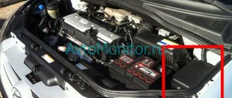
In the engine compartment of the Almera Classic, sets of fuses and relays are mounted. The first is directly next to the battery on the left side and consists of the following elements (mainly with a rated current of 15 Amps - 4, 5, 9, 17, 21, 22, 23):
Location of fuse boxes under the hood
- 1, 2, 3, 8, 15, 16, 28 – reserve;
- 4 – signal;
- 5 – throttle valve regulator;
- 6 – dimensions (10A);
- 7 – electronic power unit control unit (10A);
- 9 – ignition coils;
- 10 – ignition switch (30A);
- 11, 12, 13 – ABS (20A);
- 14, 29 – first and second main protective element (65A);
- 17 – heated windshield;
- 18 – ABS (5A);
- 19 – rear fog lamp (10A);
- 20 – dashboard (20A);
- 21 – front fog lights;
- 22, 23 – high and low beam;
- 24 – generator relay (100A);
- 25, 26 – radiator cooling fans (30A);
- 27 – window lifters (30A).
Fuse numbers in the engine compartment block
The relay part of the engine space is mounted on the right wing of the Almera Classic. It includes the following relays:
- 1, 3 – low and high beam;
- 2 – anti-theft kit;
- 4, 6, 10 – radiator cooling fans;
- 5 – connector for diagnosing the anti-lock brake system;
- 7 – signal;
- 8 – air conditioner;
- 9 – automatic transmission.
Relay numbers in the block under the hood
Correct replacement of fuse links
Before replacing fuses, disconnect the negative terminal of the battery.
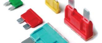
Before replacing the Almera Classic protective devices, you will need to dismantle the old element and make sure it is unsuitable. For this, special plastic tongs are used. In most cases, damage to the fuse link is visible to the naked eye. In rare cases, a continuity test using a multimeter is required. You will also need to purchase a new fuse or relay. It is necessary to select the appropriate rated current of the product. It is written on the component itself, or determined by the color scheme. Replacement is carried out in the following sequence:
A poor quality fuse may cause a fire.
- To check the quality of the new protective element, you should connect the fuse link directly through the battery using two wires. It must withstand the load without showing signs of melting;
- It is necessary to establish and eliminate the cause of burnout of protective devices. Otherwise, the new element will burn out or the electrical equipment will burn out;
- Disconnect the negative terminal of the battery;
- Remove the burnt out protective element and install a new one;
- Connect the battery terminal and check the functionality of the equipment.
Car diagram - Nissan Almera
Electrical equipment, and diagrams for it, for Nissan Almera 1995-1999. The standard equipment includes airbags for the driver and front passenger, as well as seat belts with a retractable mechanism. The interiors of these cars are highly functional. The 1.4 and 1.6 liter four-cylinder 16-valve engines from the Sunny model in this car have been upgraded, developing noticeably more power (75 and 90 hp, respectively) in the low-speed range, which contributes to faster acceleration. Since 1996, the Nissan Almera began to be equipped with a 2.0-liter diesel engine with a power of 75 hp, which attracts with its low fuel consumption. There was also a modification of the 3-door hatchback Almera GTI with a high-speed two-liter engine producing 143 hp.
Wiring diagram for switching on the starting system on Nissan Almera
A - cars with a manual transmission; B - cars with automatic transmission; 1 - ignition or instrument and starter switch; 2 - starter; 3 - selector; 4 — start blocking relay; 5 - battery; 6 — mounting block in the car interior
Battery charging circuit - wiring diagram
A - cars with a gasoline engine; B - cars with a diesel engine; 1 - generator; 2 — mounting block in the car interior; 3 - battery charging indicator lamp; 4 — contact connector of the main wiring harness; 5 - mounting block in the engine compartment
Diagram of Nissan ECCS engines GA14DE and GA16DE
Most consumable item
If you look at the diagram showing the fuses for the Nissan Almera n16, you can see that element number 22 is responsible for the operation of the cigarette lighter. In fact, this one turns out to be the most “problematic”, since it breaks down most often. In itself, it turns out to be incredibly relevant even for those who do not smoke because it is used to recharge and power a wide variety of consumers. These include both DVRs and laptops (the latter, however, work using special converters).
Cigarette lighter Nissan Almera n16
There are two options for failure here - either you will have to install a new “defender” (this will still be considered “small sacrifices”), or you will have to change the cigarette lighter itself. It's important to do it right.
In this regard, it would be useful to know what a burnt element looks like. This will help determine the problem visually, “by eye”: the damaged fusible part of the waste product is clearly visible. But there are cases when it does not work, and the thread will look like new. By the way, you can read about Nissan Almera errors on the instrument panel using the link.
The replacement process will be similar in both the cabin and engine versions. You can consider the process of replacing the salon version:
- The hood opens and the battery is disconnected.
- Next, remove the cover from the element where the block itself is located.
- Carry out an inspection to identify a failed cigarette lighter fuse.
- Remove using tongs if one is found.
- Install the new one and reassemble in reverse order.
- Don't forget to connect the battery.
Main causes of burnout
To avoid having to change such “defenders” too often in the future, it is best to know the reasons for their breakdown (otherwise the new one will not “live” for long either). The most common include:
- frequent contact of the electrical circuit with moisture (and subsequent oxidation);
- poor contact of the protection element itself with the terminals (defective product);
- failure or break of the wire (you will need to resolder the broken section).
The only thing I would like to warn against is installing amateur elements instead of normal factory relays (usually paper clips or wire). Such “know-how” can negatively affect the operation of the entire electrical circuit and even lead to a fire in the fuel pump.
How to change the cigarette lighter itself
Replacing a Nissan Almera cigarette lighter
If the problem is not in the fuse, then a global replacement is necessary. In this case, the following step-by-step recommendations will be useful:
- The negative battery terminals are disconnected. Now you will need to remove the lining from the floor tunnel.
- Pull out the cartridge.
- Pass the blocks with the wires of the parts and the lamps from the backlight into the holes made in the floor.
- Squeeze the lamp screen so that its claws can come out of the slots located in the cigarette lighter LEDs. Remove it.
- Press the socket latch so that it can disengage with the light guide.
- Push the nest outward - it should come out of the cladding.
- Remove the socket from the cigarette lighter - everything will work out if you thread the block with wires through the hole.
- Now heat the coil from the cigarette lighter for at least 20 seconds. The cartridge should then return to its original position with a click. If this does not happen, you should adjust it by straightening or bending its contacts.
- Squeeze the plastic latches on the light guide and push it outwards, thus pulling it out of the lining.
- Reassemble everything in reverse order. When the light guide is installed, it must fit into the slot made on the cladding.
Video on replacing blown fuses:
Previous article: Fuse box Nissan Almera n16 Next article: Electrical equipment Nissan Almera classic, n16, n15
Let's look into the engine block
The space under the hood is represented by other “defenders”. Their list is quite extensive: the elements protect numerous vehicle systems - from the battery and generator to the washer filler plug in the glass reservoir.
All of them are located in the space between the battery itself and the engine. Graphically, the same fuse diagram in the Nissan Almera Classic will look like this:
Rice. 4. Fuse diagram in the engine block.
The circuit for Nissan Almera n16 includes a relay. More powerful consumers are connected via relays (including headlights, fuel pump, fan motors).
Rice. 5 Relay in the motor.
These elements are located on the left side of the engine. Each of them has its own functionality:
R1 — fan (the radiator from the cooling system is activated);
R2 — front fog lights;
R4 - signal for the steering wheel;
R5 - radiator fan;
R6 - light for headlights and interior;
R7 - starter functionality.