Blocks in the cabin
Fuse box
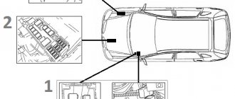
Option 1
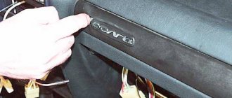
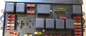
It is located in the cabin, above the glove compartment and consists of two parts. To access, you need to slide the protective strip.
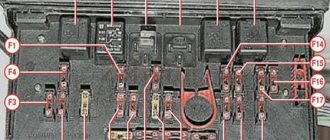
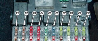
Photo - diagram
Description
Left block
| 1 | 25A Heater (air conditioning) electric motor |
| 2 | 15A High beam right headlight |
| 3 | 15A Main beam of the left headlight, high beam headlight indicator |
| 4 | 10A Low beam right headlight |
| 5 | 10A Low beam left headlight |
| 6 | 10A Rear fog light |
| 7 | 20A 2008 Radio equipment 2005 Injection system devices |
| 8 | 20A Cigarette lighter , horn relay, horns |
| 9 | 15A 2008 (Euro-3): Engine management system 2008 (Euro-2): Electric fuel pump, oxygen sensor 2005: Heated mirrors, electric fan relay coil |
| 10 | 10A 2008 (Euro-3): Electric fuel pump 2008 (Euro-2): Engine management system 2005: Radio equipment |
| 11 | 5A 2008 (Euro-3): Engine control unit 2008 (Euro-2): Turn signals, relays and turn signal indicators 2005: Electric drives of exterior mirrors, forced idle economizer unit (ZMZ-402), oxygen sensor (3M3-40621) |
| 12 | 15A Engine compartment lamp, glove box lamp, interior lamp |
| 13 | 10A 2008 (Euro-3): Turn signals, relays and turn signal indicators 2008 (Euro-2): Engine control unit, ignition coils 2005: Windshield wiper, headlight washer relay |
Fuse number 8 at 20A is responsible for the cigarette lighter.
| 1 | 25A Fog lights |
| 2 | 15A Heater (air conditioning) control unit, rear window heating relay, rear window heating (1 mode), additional heater |
| 3 | 15A Speedometer sensor, instruments, warning lights, reverse light, electric fan relay |
| 4 | 10A Brake lights |
| 5 | 10A Hazard Alarm |
| 6 | 10A Left side lights, fog light relay, side light indicator |
| 7 | 20A Heated rear window (mode 2), interior lamps, rear door, rotating headlight (medical car) |
| 8 | 20A Glass lifts |
| 9 | 15A 2008: Windshield wiper, headlight washer relay 2005: Ignition coils |
| 10 | 10A Anti-lock Brake System ABS |
| 11 | 5A 2008: Power and heated exterior mirrors 2005: Turn signals, relays and turn signal indicators |
| 12 | 15A Locking |
| 13 | 10A Right side lights, electric headlight range control, lighting: trunk, license plate, instruments, cigarette lighter, switches, medical sign lights, taxi |
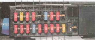
Option 2
Located in the cabin under the instrument panel, on the driver's side behind the protective cover.
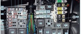
Scheme
Designation
Upper block
| 1 | 25A Heater (air conditioning) electric motor |
| 2 | 15A High beam right headlight |
| 3 | 15A Main beam of the left headlight, high beam headlight indicator |
| 4 | 10A Low beam right headlight |
| 5 | 10A Low beam left headlight, low beam headlight warning light |
| 6 | 10A Rear fog light |
| 7 | 20A Radio equipment |
| 8 | 20A Cigarette lighter , horn relay, horns, instrument cluster, clock |
| 9 | 15A Euro-3 Engine management system, Euro-2 diagnostic connector: Electric fuel pump, oxygen sensor (ZMZ-40621) |
| 10 | 10A Euro-3 : Electric fuel pump Euro-2: Engine management system, diagnostic connector |
| 11 | 5A Euro-3: Engine control unit Euro-2: Turn signals, relays and turn signal indicators |
| 12 | 15A Engine compartment lamp, glove box lamp, interior lamp |
| 13 | 10A Engine control unit, ignition coils (ZMZ-40621) |
Fuse number 8 at 20A is responsible for the operation of the cigarette lighter.
| 1 | 25A Fog lights |
| 2 | 15A Heater (air conditioning) control unit, heater valve, front lamp, interior temperature sensor, fog lamp relay coil, + (ZMZ-40525, Chrysler 2.4L-DOHC (Euro-3): speedometer sensor, reverse light, instrument cluster ) |
| 3 | 15A Euro-3: Hazard alarm Euro-2: Speedometer sensor, reverse light, instrument cluster |
| 4 | 10A Brake lights |
| 5 | 10A Euro-3: Direction indicators, relays and indicators Euro-2: Hazard warning lights |
| 6 | 10A Left side lights, side light indicator |
| 7 | 20A Heated rear window and heated exterior mirrors |
| 8 | 20A Window lifters |
| 9 | 15A Windshield wiper and washer |
| 10 | 10A Anti-lock Brake System ABS |
| 11 | 5A Electric drive of exterior mirrors |
| 12 | 15A Locking |
| 13 | 10A Right side lights, electric headlight range control, headlight washer relay, trunk light, license plate light, instrument light, cigarette lighter light, switch light, medical sign light, taxi |
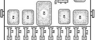
Relay block
It is attached near the left drain, under the driver's side panel, behind the trim.
Scheme with decoding
- Warning lamp relay
- Starter relay
- Fog light relay
- Signal relay
- Heated rear window relay
- High beam relay
- Low beam relay
- Rear fog lamp relay
- Wiper relay
- Engine cooling fan relay
Separately, outside the block, on the turn signal switch itself, there is a turn signal relay.
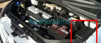
Fundamental differences in the design of the fuse box depending on the Gazelle model
This is what the new fuse box looks like
The design differences of the modification of the Gazelle class, based on various electrical equipment protection systems, can be divided into the following main groups and their features can be highlighted. Watch the video on how to install a new fuse box.
Cars with carburetor-type gasoline engines
- Cars produced before 2003:
- equipped with old-style electrical fuse modules with cylindrical type fuses with a nominal value of 8 and 16A;
- control relays are installed separately from the mounting block;
- the engine compartment block (BPR-2) has power fuses of 40A for the light circuit and 60A for the general plus.
- Models 2003-2010:
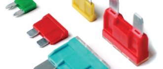
- new-style units with plastic fuses with protection thresholds of 5, 10, 15, 20 and 25A were installed, depending on the equipment;
- control relays are also located independently of the unit;
- the power protection module can be different: BPR-2 with protection of 90A for the light and generator circuits and 60A for the general plus.
- BPR-4 for cars with a pre-installed anti-lock braking system and additional 25 and 40 A electrical fuses.
Cars with gasoline injection engines
- The main fuses of plastic type 25, 10, 15, 20 and 5A for various circuits are combined into a single mounting module located in the cab.
- The main control relays are included in the unit.
This is what control relays look like for a Gazelle car
Installation process of protective relays
Diesel vehicles
- A main safety module is installed, similar to fuel-injected cars, with additional 5A electrical fuses for the engine management system.
- Modified engine compartment, including protected circuits:
- air heating system with 125A protection;
Schematic design of the air heating system in a gazelle
Diagram with car fuse sizes
The variety of factory configurations of Gazelle cars, both in terms of the pre-installed engine and additional equipment, and the multiplicity of their combinations leads, in turn, to differences in the electrical protection system and the design of the mounting block.
Thus, the Gazelle fuse box is a mandatory element of the protective mechanism of the vehicle’s electrical equipment and is implemented taking into account the design features of a specific modification of the vehicle.
The two-level construction of the safety circuit provides reliable protection of on-board devices, both from a short circuit in the machine network and from voltage surges, thereby ensuring their trouble-free operation.
9.2.2 Fuse box / GAZ 31105
| 1. Most electrical circuits are protected by fuses located in two blocks on the instrument panel. The fuse numbers are on the block housings. The numbers of fuses, the devices of the circuits they protect, as well as the current strength are given in table. 9.1. |
| WARNING Do not replace a blown fuse with a fuse of a different rating or a homemade jumper. |
| 2. To access the fuses, slide the decorative trim with the inscription “Volga” located on the cover of the fuse blocks to the right. Insert your finger into the hole and pull the fuse box cover towards you to remove it. If the cover is difficult to remove, you can pry it off with a screwdriver |
| 3. To remove fuses from the block, it is recommended to use tweezers, which are included with the set of spare fuses. Fuse housings are colored according to the current strength ( Table 9.2 ). |
| 4. To remove the fuse blocks, you need to remove two screws securing both blocks. |
| 5. Pull the fuse blocks towards you from the panel so that the plug blocks of the blocks come out of the panel. Label the connectors, disconnect them and push them back into the hole in the instrument panel. |
| 6. An additional block of two fuses is installed on the left mudguard under the hood: a 30 A fuse protects the engine cooling fan circuit; A 60 amp fuse protects all circuits except the starter circuit. To replace fuses, remove the cover of the block and remove the two screws securing the fuse and replace it. |
| NOTE Spare fuses are secured under the plate on the back of the unit cover. |
Video for the article:
REPLACING FUSES FOR GAS 3110
Wiring Gas 31105 is shorted, the reason has been found
Volga 31105 wipers refuse to work
Fuse box near the battery. Which wire goes where?
Turn signals do not work on GAZ 31105
Replacing fuses and relays on a Volga GAZ 31105 car
Tools:
- open-end wrench 10 mm
- Phillips screwdriver medium
Notes:
On a Volga GAZ 31505 car, remove the wire terminal from the “negative” terminal of the battery.
1. To replace the fuses installed in the engine compartment of the GAZ 31105 car, press the block cover latches on both sides and remove the cover.
2. Using a 10mm wrench, unscrew the two nuts securing the faulty fuse.
3. We remove the wire ends and the faulty fuse from the studs. Spare fuses are stored under the cover plate. The tripping current value is stamped on the fuses.
4. Install a new fuse (with the appropriate response current), put the wire lugs on the studs and tighten the fastening nuts. 5. To replace the fuses installed in the interior of the Volga GAZ 31105 car, move the emblem all the way.
6. By prying the hole, remove the block cover.
7. The fuses in the blocks are arranged in numerical order from left to right. The circuits protected by fuses are indicated on the back of the cover. Complete with spare fuses, the GAZ 31105 car comes with tweezers for removing fuses.
8. We remove the faulty fuse. We insert a new fuse into the block and install the cover.
9. To access the relay, use a Phillips screwdriver to unscrew the four screws securing the left side trim of the front end and remove the trim.
10. Since the relays do not have fixed mounting points, and their relative location may differ on Volga GAZ 31105 cars of different years of production. When searching for the right relay, you should be guided by the color and number of wires, comparing them with the diagram.
11. To replace the relay, unscrew the fastening screw and disconnect the wire block. Install the relay in reverse order.
The article is missing:
- Photo of the instrument
- High-quality photos of repairs
Possible wiring faults
What malfunctions in the wiring of a GAZ 31105 with a Chrysler engine, GAZ 31029 or any other model can occur:
- Lack of contact. Such a malfunction may be associated with a break in the electrical wiring, oxidation of the outputs, or their burning. If the contact is oxidized, then it needs to be cleaned, if the wire is broken, then it must be restored, if the reason lies in burning, then first you need to eliminate the problem of overvoltage. It is quite possible that the connector simply came out of the socket; this often happens when the plug is poorly secured and constantly driving on uneven roads.
- Battery discharge. This problem most often occurs in the cold season - in the cold, batteries are most susceptible to discharge. If this happens during the warm season, then you need to check the battery charge, the level and density of the electrolyte, as well as the case for damage.
- Circuit break. A malfunction of this type is diagnosed by searching for the damaged area manually or using a tester. The break must be eliminated by replacing the wire, and the replaced wire should also be wrapped with electrical tape - this will create an additional layer of insulation. When laying wires, make sure that they are not exposed to moving mechanisms, otherwise this will lead to another insulation breakdown and breakage.
- Burnout of the safety element. This problem is most relevant for cars that have power surges in their on-board network. If the voltage surges are noticeable, then the fuse simply will not be able to withstand the load, which will lead to its failure.
The fuel pump does not pump: causes and diagnostics
Let's start with the fact that if the gas tank is full, the battery is charged, the spark plugs are dry and there is a spark, the starter turns the engine normally, but the engine does not seize, then you should pay attention to the gas pump. A common problem is that there is no power to the fuel pump after the ignition is turned on. In a similar way, the malfunction manifests itself in motion, when the power to the fuel pump is lost and the engine suddenly stalls.
An equally important point is how much the fuel pump pumps. In other words, the pump may hum and buzz (power is being supplied), but not create the required pressure in the fuel line. The pressure in the fuel system with a working fuel pump must be more than 3 bar (which depends on the specific car model). The indicated pressure is accumulated in the fuel rail and has an indicator of 300 kPa and above.
To check, you need to measure the pressure in the fuel rail with a pressure gauge, taking into account the indicators that are the norm for a specific car model. Using the example of injection VAZs, the pressure when the ignition is turned on is 3 atmospheres, at idle the figure is 2.5 atmospheres, when you press the gas 2.5-3 atmospheres. This method will help you accurately determine:
- malfunction of the fuel pressure regulator in the rail;
- breakdown of the fuel pump or a noticeable decrease in its performance due to wear;
- severe contamination of filters (fuel filter and/or fuel pump mesh);
In the second case, when you press the gas, the pressure does not increase; in the latter case, the pressure gauge needle rises, but very slowly or jerkily.
A decrease in pressure below the norm will lead to the fact that the engine may not start or start with difficulty, stall, jerk, operate unstably and with failures. If this happens due to the fault of the pump and not the fuel filter, then there is a high probability that the coarse filter screen of the fuel pump is clogged. In this case, there is no need to change the fuel pump itself, since it will be enough to replace or even clean the mesh.
If you suspect that there is no voltage to the fuel pump, there is a quick way to check. It is enough to turn the ignition key and listen, as when you turn the key you should hear a slight hum from the fuel pump. If such a buzzing noise is not heard, it means there is no power to the fuel pump, there are problems with the wiring, etc.
Also in the general list of possible reasons why the fuel pump does not pump, the following are noted:
- failure of the fuel pump fuse;
- fuel pump relay failure;
- problems with the ground of the fuel pump;
- malfunction of the electric motor of the fuel pump;
- oxidation or damage to fuel pump contacts and terminals;
- the fuel pump itself is faulty;
Wiring to the fuel pump
On most cars, the wiring to the fuel pump consists of three wires: “plus”, “minus”, and also a wire for indicating the amount of fuel in the gas tank. If the fuel pump does not pump, then the cause may be a lack of power.
To check the power to the fuel pump, just take a 12-volt light bulb and supply it with power from the external connector of the fuel pump. After turning the ignition, the control lamp should light up. If this does not happen, then the problem is in the external circuits. If the lamp comes on, it will indicate the need to check the internal contacts of the fuel pump.
To check the external wiring, you should alternately connect the positive and negative contacts, which are removed from the fuel pump power connector, to the ground of the pump. The contacts must also be connected to the fuel pump relay. If you place the negative contact on ground, after which the ignition is turned on and the light comes on, then this means that this contact is faulty. If the light bulb does not light up, then problems with the “plus” are obvious. If you place a contact on the relay and the light comes on, there is probably damage to the wire on the section that connects the relay and the fuel pump itself.
Fuel pump electric motor
If checking the pressure in the fuel rail and the external wiring to the fuel pump gives positive results, then you should check the fuel pump motor. This electric motor is responsible for circulating gasoline inside the fuel pump.
When checking, you need to take into account that the terminals on the fuel pump themselves tend to oxidize, as a result of which power is not supplied and the pump does not pump. In this case, the motor is working, but the terminals need to be cleaned or re-soldered.
Automatic headlight switching diagram.
Modern cars use an automatic headlight switching system. It can be performed using various algorithms. In some foreign-made cars, the headlights turn on when the engine is started, in others when natural light decreases (at dusk, entering a tunnel, etc.). On domestic cars, this scheme is used on the Priora luxury version. In these cases, the headlights are controlled by an electronic unit. This makes troubleshooting somewhat more difficult, and in some cases it is impossible to do without computer diagnostics.
Replacing wiring
Wiring for a Gazelle 406 engine with pinout of ECU connector terminals.
Changing all the electrical wiring of a Gazelle when replacing an engine from 402 to 406 is of course not impractical.
The fact is that on newer versions of Gazelles, the connection diagram of certain devices also changed:
- Gazelle 406 wiring is integrated into the standard electrical system in the engine compartment;
- electronic components and control devices are connected using terminals;
- The voltage and correct connection are checked using testers.
After assembling the wiring into a single whole, its functionality is checked. Subsequently, the operation of the power unit is adjusted.
Conclusions: Replacing the power unit inevitably affects the change in the standard electrical wiring of the car
That is why it is important to have a visual aid at hand when carrying out such an operation, and the Gazelle’s factory wiring diagram will allow you to avoid mistakes
Structural structure of the Gazelle fuse box
The electrical circuit protection system in Gazelle cars is implemented using a two-level model, which provides additional stability in the operation of electrical equipment and has the following features.
Fuses for Gazelle electrical equipment
- The first protective level is provided by power fuses located in a separate mounting block under the hood of the car. Their operation is designed for a significant change in current in the circuit, and their main purpose is short circuit protection. In this case, two main circuits of the electrical circuit are separated, including:
- main positive circuit, excluding lights, generator and starter;
- positive generator circuit and light circuit.
In modifications equipped with an anti-lock braking system, two additional electrical fuses are installed that are directly responsible for this function.
Electrical fuses in the electrical network
Electrical headlight connection system for Gazelle
Designations on the relay of the Gazelle mounting block
This is what the old fuse box on a Gazelle looks like
This is interesting: Cleaning the drainage holes of GAZ-31105
Further modernization
Plans to increase sales volumes were not destined to come true. There are several reasons for this:
- Quite high costs of operating a GAZ car with low functionality;
- Obsolescence of the design in terms of passive safety;
- Poor body corrosion resistance;
- Lack of comfort features.
The wiring diagram of the GAZ 31105 with the Daimler Chrysler power unit complied with European standards. All this forced the automaker to engage in deep restyling, as a result of which the GAZ 31105 model appeared in 2004.
Among its features it should be noted:
- DOНC power unit with a volume of 2.4 liters from Daimler Chrysler;
- Electronic throttle pedal;
- A new instrument panel, redesigned to meet safety requirements;
- A control panel for power windows and exterior mirror adjustment located on the driver's door;
- New headlights and taillights;
- Air conditioner.
All this led to the fact that the electrical wiring diagram of the GAZ 31105 changed radically. Although the car became more similar in functionality to its foreign counterparts, it nevertheless could not compete with them.
Original photo of electrical equipment of GAZ 31105 with Daimler Chrysler engine
Source
Repair GAZ Volga (31105): Fuel pump relay
- Repair manuals
- Volga 31105 2004-2009
- Fuel pump relay
The fuel pump relay is installed in the engine compartment on the same bracket as the diagnostic connector and the main relay.
You will need a 10mm socket wrench (head).
1. Turn off the ignition and remove the negative terminal of the battery.
2. Align the mounting bolt and remove the relay.
3. Remove the wire block from the relay terminals.
4. Install the relay in the reverse order of removal.
Download information from the page
↓ Comments ↓
Content. GAZ-31105 "Volga"
Section 1. GENERAL INFORMATION ABOUT THE VEHICLE
Design features Vehicle registration data Vehicle keys
Section 2. RECOMMENDATIONS FOR OPERATION AND MAINTENANCE
Safety rules and recommendations Checking the vehicle before leaving Breaking in the vehicle Tools and accessories Using a jack Towing the vehicle
Section 3. FAULTS ON THE TRAIL
The engine will not start Malfunction of the fuel injection system Interruptions in the engine The car does not accelerate well The engine stalls while driving The oil pressure has dropped The engine is overheating The battery does not recharge There are unusual knocking Problems with the brakes A punctured wheel
Section 4. ENGINE
Useful tips Removing and installing the engine splash guard Replacing the oil and oil filter element Removing, installing and adjusting the tension of the auxiliary drive belt Replacement of the power unit mounts Removing and installing the engine Replacing the engine seals Repairing the gas distribution mechanism Removing and disassembling hydraulic chain tensioners Assembly (“charging”) and installation of hydraulic chain tensioners Removal, repair and installation of camshafts Removal and installation of the cylinder head Repair of the cylinder head Removal, repair and installation of the intermediate shaft Removal, repair and installation of the connecting rod-piston group Removal, repair and installation of the crankshaft Troubleshooting and repair of the cylinder block System Lubrication Cooling System Power System Exhaust System
Section 5. TRANSMISSION
Clutch Gearbox Cardan drive Rear axle
Section 6. CHASSIS
Front suspension Rear suspension
Section 7. STEERING
Checking the technical condition of the steering Adjusting the play in the steering gear Steering column Steering gear without power steering Steering linkage Steering gear with power steering
Section 8. BRAKE SYSTEM
Checking and adjusting the brake system Bleeding the brake system hydraulic drive Removing and installing the brake pedal Master brake cylinder Vacuum booster Pressure regulator Front wheel brakes Rear wheel brakes Parking brake
Section 9. ELECTRICAL EQUIPMENT
Battery Fuses and relays Generator Starter Engine management system Lighting and light signaling Replacing switches Horn Windshield wiper Windshield washer Removing and installing instrument cluster
Section 10. BODY
Useful advice Replacing the buffers Removing and installing the radiator trim Hood Removing and installing the front wing Front door Rear door Trunk lid Removing and installing the outside rear view mirror Removing and installing the instrument panel Removing and installing the center console Seats Removing and installing interior attachments Heater Replacing the windshield and rear glass Removal and installation of seat belts Removal and installation of the rear shelf Body care Anti-corrosion protection of the body
Section 11. CAR CARE
Checking the car before leaving Car washing
Section 12. PURCHASE OF SPARE PARTS
Engine oil Transmission oils Greases Coolants Brake fluid
Section 13. TRIP TO A STATION
Similar chapters from other books
External glass and porcelain insulation of electrical equipment and switchgear
External glass and porcelain insulation of electrical equipment and outdoor switchgear Question. How should the specific effective creepage distance of external porcelain insulation, as well as insulators of flexible and rigid external open conductors, be selected? Answer. Must be selected based on data
Placement and installation of electrical equipment
Placement and installation of electrical equipment Question. What electrical equipment and devices can be installed in EMF? Answer. Can be installed: electric machines; electric machine converting units; starting and control devices for
Placement of electrical equipment
Placement of electrical equipment Question. What conditions must the placement of electrical equipment of adjustable electric drives satisfy? Answer. Must satisfy the general requirements set out in chapters 4.3, 5.1, 5.3 of these Rules, as well as the technical specifications for
Classification and marking of explosion-proof electrical equipment according to GOST 12.2.020-76
Classification and marking of explosion-proof electrical equipment according to GOST 12.2.020-76 Question. What are the established explosion protection levels for electrical equipment? Answer. The following levels have been established: electrical equipment of increased reliability against explosion - explosion-proof
Electrical faults
Malfunctions of electrical equipment The battery requires attention The battery discharges slowly during operation. The starter cranks the engine at a low speed. Current leakage through damaged insulation of any wire or device - from here
4.3.1. General overview of motivational processes in quality management
4.3.1. General overview of motivational processes in quality management The concept of “motive” is often used to denote such psychological phenomena as aspiration, desire, intention, fear, etc., which are reflected in a person in the form of readiness for activities leading to
Military options and equipment on the UAZ-469 vehicle
Military options and equipment on the UAZ-469 car With the start of serial production, the UAZ-469 immediately became the main light multi-purpose vehicle of the Soviet Army and the armed forces of all fraternal and allied countries. In the 1970s, it was exported to 70 countries. These cars were
General information about the car
General information about the car Below are the main technical data and presented in the form of logical diagrams operational methods for troubleshooting the latest modernized model of the Volga GAZ-3110 car with a sedan body and with a ZMZ-402 engine,
( 2 ratings, average 4 out of 5 )
Gas fuel pump 31105 does not work
3.9 / 5 ( 74 voices)
Model 3110 of the Gorky Automobile Plant was launched into production in 1997 and was conceived as a more modern and improved solution, comparable to the equipment of the middle class of foreign cars, while the price was noticeably lower.
But as time has shown, this modification also turned out to be uncompetitive, and therefore, after several years, its production was completely discontinued, but there are still many cars of the model in question on the roads, so the GAZ 3110 wiring diagram will be useful to those who carry out repair work.
( 2 ratings, average 4 out of 5 )
GAZ 31105 | Checking the fuel pump relay
Checking the fuel pump relay
| GENERAL INFORMATION |
The fuel pump relay is located in the relay board, location 4, on the driver's side under the instrument panel assembly. It must be checked if the pump does not work.
| EXECUTION ORDER |
| 1. Remove the No. 28 fuel pump fuse. | |
| 2. Connect a diode warning lamp using an auxiliary wire between ground and one of the two fuel pump fuse contacts. | |
| 3. Remove the upper trim in the area of the driver’s feet, on the left, and refer to the subsection Removing and installing the pocket on the driver’s side . | |
| 4. Turn on the starter. You should be able to hear the fuel pump relay turn on. In addition, the diode control lamp should light up. | |
| 5. If the relay does not turn on, check the supply voltage and control. | |
| 6. If the diode warning lamp does not light up, although the relay turns on, repeat the test on the other fuse contact. | |
| 7. If the diode warning lamp does not light again, check the wire between pin 23 at the relay, location 4, and the fuel pump fuse. If there is a break, repair it. | |
| 8. If relay power, control, and relay wires are OK, replace the fuel pump relay. | |
| Power check | |
| Remove the fuel pump relay from the relay board (relay location #4). | |
| Turn on the ignition. | |
| Connect the voltmeter in series: | |
– between contact 19 (plus the ignition switch) and ground;
– between pin 17 (battery plus) and ground.
Required value: 12 V (battery voltage).
Otherwise, check the wire break according to the electrical diagram and repair it.
| Turn off the ignition. |
| EXECUTION ORDER |
| 1. Connect a diode test lamp with an auxiliary wire between pin 16 (control ground from the engine control unit) and pin 17 (plus) of the relay base. | |
| 2. Turn on the starter. The LED should light up. Otherwise, find a break in the wire to the injection control device and repair it or replace the control device (service station work). |
Diode control lamps have low current consumption. If the starter is not turned on, they have a faint glow and do not go out completely.