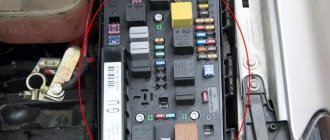
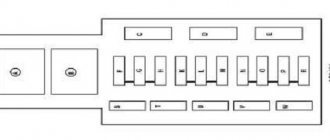
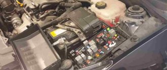
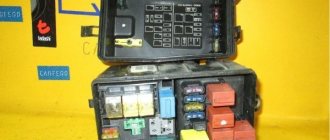
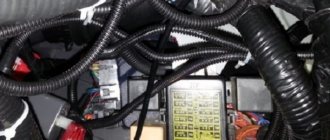
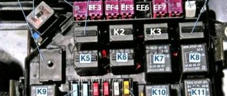
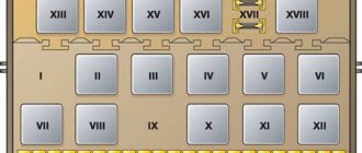
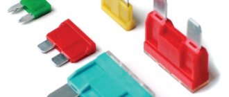
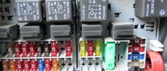
Fuse and relay mounting block under the hood of the Opel Astra J
The mounting block is located near the battery.
Relay Description:
K1 - spare relay K2 - starter relay K3 - transmission relay K4 - Rear window heater relay K5 - Headlight washer pump relay K6 - Left daytime running light bulb relay, low beam headlights K7 - Fuel pump relay K8 - Right daytime running light bulb relay headlights K9 – Fuel heater relay (diesel engine) K10 – spare relay K11 – Low speed cooling fan relay K12 – High speed cooling fan relay K13 – Medium speed cooling fan relay 1 K14 – Main ignition relay
Description of maintenance-free relays located inside the mounting block:
KR3 – Horn relay KR6 – Rear window washer pump relay KR7 – Rear window wiper relay KR11 – Windshield washer pump relay KR29 – Air conditioner compressor clutch relay KR46 – Front fog lamp relay KR48 – High beam headlight relay KR94 – Fuel pump release drive relay KR95A hatch – Rear tailgate lock release relay
Table of circuits protected by fuses in the engine compartment of the Opel Astra J
| Fuse number | Current strength, A | Circuits protected by a fuse |
| F01 | 80 | K34 Glow plug control unit (diesel engine) |
| F02 | 80 | K43 Power steering control module |
| F03 | 100 | E40 Auxiliary electric heater |
| F04 | 80 | G10 Cooling fan motor |
| F1 | 10 / 20 | Engine Control Module (ECM) Gasoline/Diesel |
| F2 | 10 | Heated Oxygen Sensor 1, B52B Heated Oxygen Sensor 2, B75B Mass Air Flow/Intake Air Temperature Sensor, E41 Engine Cooling Thermostat Heater, Q12 Evaporative Emissions Canister Purge Valve, Q22 Intake Manifold Geometry Variable Solenoid Valve |
| F3 | 15 | Q17A Fuel Injector 1, Q17B Fuel Injector 2, Q17C Fuel Injector 3, Q17D Fuel Injector 4, T8 Ignition Coil |
| F4 | 15 | Not used |
| F5 | 15 | Not used |
| F6 | 7,5 | A9A Outside rear view mirror - driver, A9B Outside rear view mirror - passenger |
| F7 | 5 | KR20B Radiator Fan Medium Speed Relay 1, G10 Radiator Fan Motor |
| F8 | 7.5 | B52A Heated Oxygen Sensor 1, B52B Heated Oxygen Sensor 2, B75B Mass Air Flow/Intake Air Temperature Sensor |
| F9 | 7.5 | K9 Body Control Module, Rear Window Sensor |
| F10 | 5 | K9 Body Control Module, Battery Sensor |
| F11 | 7,5 | KR95B Liftgate release relay 1 |
| F12 | 5 | Headlight control module K26, Adaptive front lighting module |
| F13 | 20 | Not used |
| F14 | 20 | KQ7 Rear window wiper relay, M45 Rear window wiper motor |
| F15 | 10 | K20 Engine Control Module (ECM) |
| F16 | 30 | KR27 Starter relay |
| F17 | 10 | K71 Transmission control module |
| F18 | 40 | E18 Rear window defogger mesh |
| F19 | 30 | M74D Power window motor - driver, M74P Power window motor - passenger |
| F20 | 30 | M74LR Power window motor - left rear, M74RR Power window motor - right rear |
| F21 | 30 | K17 Electronic brake control unit (EBCM) |
| F22 | 10 | E13L Headlight assembly - left (high beam) |
| F23 | 25 | KR2 Headlight washer pump relay |
| F24 | 15 | E13R Headlight assembly - right (low beam, xenon) |
| F25 | 15 | E13L Headlight assembly - left (low beam, xenon) |
| F26 | 15 | E29LF Fog lamp - left front, E29RF Fog lamp - right front |
| F27 | 30 | KR22 Fuel heater relay (diesel engine) |
| F28 | Not used | |
| F29 | 30 | K83 Parking brake control module (J71) |
| F30 | 60 | K17 Electronic brake control unit (EBCM) ABS |
| F31 | not used | |
| F32 | 5 | K36 Airbag Diagnostic and Monitoring Module |
| F33 | 15 | K28 Control module for headlight range control (AFL) |
| F34 | Not used | |
| F35 | 5 | S52 Outside rear view mirror switch, S79D Power window switch - driver |
| F36 | Not used | |
| F37 | Absorber purge solenoid valve | |
| F38 | 20 | KR28 Vacuum pump relay (petrol engine) |
| F39 | 20 | K27 Fuel pump flow control module (petrol engine) |
| F40 | 10 | Windshield washer motor |
| F41 | 10 | E13R Headlight assembly - right (high beam) |
| F42 | 40 | KR20C Low speed cooling fan relay (petrol engine), KR20B Medium speed cooling fan 1 relay (diesel engine) |
| F43 | 30 | M75 Windshield wiper motor |
| F44 | Not used | |
| F45 | 30 | G10 Engine cooling fan motor (petrol engine) |
| F46 | Not used | |
| F47 | 15 | P12 Horn |
| F48 | 60 | KR20B Cooling Fan Medium Speed 1 Relay, KR20C Cooling Fan Low Speed Relay, KR20D Cooling Fan High Speed Relay |
| F49 | Fuel pump | |
| F50 | 10 | S30 headlight switch, M29L headlight leveling drive - left, M29R headlight leveling drive - right |
| F51 | Throttle assembly | |
| F52 | Heating of crankcase gases | |
| F53 | 7,5 | K20 Engine Electronic Control Module (ECM), K34 Glow Plug Control Module (GPCM) (Diesel Engine), K71 Transmission Control Module (Automatic Transmission) |
| F54 | 7,5 | B19C Brake Power Vacuum Switch, K27 Fuel Pump Control Module, B116 Water in Fuel Sensor, E40 Auxiliary Electric Heater, K33 HVAC Control Module, P16 Instrument Cluster, B108 Air Quality Sensor, B19C Brake Power Vacuum Switch, B75B Sensor air mass flow/intake air temperature |
Engine compartment
The safety block is located in a visible and easily accessible place. To replace a burnt-out insert, simply release the latches holding the unit cover, under which the protective fuses are located.
| Number | What is he responsible for? |
| 1 | Engine control |
| 2, 8 | Oxygen sensor monitoring |
| 3, 4 | Fuel supply / ignition system operation |
| 6 | Heated side mirrors |
| 7 | Fan regulator |
| 9, 18 | Heated rear window |
| 10 | Accumulator battery |
| 11 | Opening the luggage compartment (handle operation) |
| 12, 33 | Adaptive lighting |
| 14 | Rear wiper motor |
| 15 | Engine |
| 16 | Starter operation |
| 17 | Gear box |
| 19, 20 | Front/rear window motor |
| 21, 30 | ABS |
| 22, 41 | High beam left and right headlights |
| 23 | headlight washer |
| 24, 25 | Low beam (xenon) lighting right/left headlight |
| 26 | Fog lights |
| 27 | Fuel heating (for diesel engines) |
| 29 | Electric parking brake |
| 32 | Airbags |
| 35 | Power windows |
| 37 | Operation of the adsorber slip magnetic valve |
| 38 | Vacuum electric pump |
| 39 | Fuel control |
| 40 | Windshield and rear window washers |
| 42, 45, 48 | Radiator fan |
| 43 | Front wipers |
| 47 | Klaxon |
| 49 | Fuel pump |
| 50 | Automatic headlight adjustment |
| 51 | Chokes |
| 52 | Heating of gases in the crankcase |
| 53 | Gearbox and engine |
| 54 | Car wiring |
Mounting block of fuses, fuses and relays in the trunk of the Opel Astra J
In the trunk of a car, the mounting block is located on the left side behind the lid. To access you need to remove the cover.
Relay Description:
K1 – Ignition relay 0 K2 – Ignition relay 1 K3 – Door lock relay K4 – Not used
Table of circuits protected by fuses in the trunk of the Opel Astra J
| Fuse number | Current strength, A | Circuits protected by a fuse |
| F1 | 40 | K101 Trailer interface control module |
| F2 | 30 | X88 Trailer wiring harness connector |
| F3 | Parking assistance system | |
| F4 | Not used | |
| F5 | Not used | |
| F6 | Not used | |
| F7 | 10 | K29 Seat heating control unit, K104P Seat lumbar support control unit - passenger |
| F8 | Not used | |
| F9 | Not used | |
| F10 | 5 | K9 Body Control Module |
| F11 | 11 | K65 Tire pressure indicator module, K68 Trailer light converter |
| F12 | Not used | |
| F13 | 20 | X88 Trailer wiring harness connector |
| F14 | Not used | |
| F15 | 7,5 | S52 Outside rear view mirror switch, S79D Power window switch - driver |
| F16 | 5 | A10 Interior rear view mirror |
| F17 | Not used | |
| F18 | Not used | |
| F19 | 10 | K32 Steering wheel heating control unit |
| F20 | 20 | K61 Sunroof control module |
| F21 | 25 | K29 Seat heater control module |
| F22 | Not used | |
| F23 | Not used | |
| F24 | Not used | |
| F25 | Not used | |
| F26 | Not used | |
| F27 | Not used | |
| F28 | Not used | |
| F29 | Not used | |
| F30 | Not used | |
| F31 | 30 | T3 Audio amplifier (speaker system) |
| F32 | 10 | K19 Suspension control module |
Video “Replacing the Opel Astra fuse”
This video shows the process of replacing fuses in a block located in the engine compartment of an Opel Astra.
To identify the vehicle and reliably select the Opel Astra J Hatchback fuse box , you should carefully select the vehicle modification. To do this, use clarifying information with data containing: power, measured in horsepower (example 103 hp), engine size (example 1.6 liters), type (example gasoline) and model + engine code, as a rule, this parameter rarely used, but you can only find it in the vehicle title, you can also pay attention to the drive axle (there are rear, front or all-wheel drive), and a mandatory parameter is the release date, which divides the vehicle model into restyling, pre-restyling, first and last year production.
This data serves to uniquely install spare parts during a certain production period, as manufacturers are constantly upgrading cars off the assembly line.
Mounting fuse block in the interior of the Opel Astra J
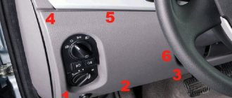
The mounting block in the passenger compartment is located under the panel on the driver's side under the glove box.
Table of circuits protected by fuses in the interior of the Opel Astra J
| Fuse number | Current strength, A | Circuits protected by a fuse |
| F1 | 10 | A22 Radio control, K33 Driver information center (DIC) display |
| F2 | 20 | K9 Body Control Module, Exterior Lighting |
| F3 | 25 | K9 Body Control Module |
| F4 | 20 | A11 Radio receiver, P5 Buzzer control unit |
| F5 | 7,5 | A12 Digital radio control unit, K82 Mobile telephone control unit, T11 Multimedia player interface module |
| F6 | 20 | Front power socket ( cigarette lighter fuse Opel Astra J ) |
| F7 | 20 | Accessory power socket |
| F8 | 30 | K9 Body Control Module, Left Headlight (Low Beam, Halogen) |
| F9 | 30 | K9 Body Control Module, Right Headlight (Low Beam, Halogen) |
| F10 | 30 | K9 Body Control Module, Door Locks |
| F11 | 40 | K8 Fan motor control module. Heating (ventilation) and air conditioning system |
| F12 | 25 | S64D Seat adjustment switch - driver, S65D Seat lumbar support switch - driver |
| F13 | Not used | |
| F14 | 7,5 | X84 Diagnostic connector |
| F15 | 7,5 | K36 Airbag Diagnostic and Monitoring Module |
| F16 | Not used | |
| F17 | 10 | A26 HVAC control panel, K33 HVAC control unit |
| F18 | 30 | KR104A Logistic mode relay 1 |
| F19 | 20 | Body control module K9 Brake lights, running lights |
| F20 | 5 | K85 Passenger detection module |
| F21 | 10 | P16 dashboard |
| F22 | 5 | S39 Ignition switch |
| F23 | 20 | K9 Body Control Module |
| F24 | 20 | K9 Body Control Module |
| F25 | Not used | |
| F26 | Not used |
Fuse location
Before you find out where the power supplies are located in the Opel Astra G, you must remember that the car should always have an additional set of fuses. If one element fails, it is advisable to immediately replace it, but in no case should you use wire.
Some car owners take an ordinary piece of wire or a paper clip and place both ends of it in the place of the burnt fuse. They motivate this by the fact that “there’s nothing wrong with it, if you drive like this for a short time before replacing the fuse.” But it is strictly forbidden to do this, otherwise it may be necessary to replace the power supply.
Power supply circuit
On Opel Astra G models, most of the fuses are located in the block, which is located under the dashboard of the car. In particular, it is installed under the dashboard on the left side opposite the driver's seat behind the glove compartment. To get to the power supply unit, you need to dismantle the facing part of the small items box, then pull the bottom of the unit and bring it into working position. Below is a diagram of the device's location.
In addition, these car models also have an additional unit responsible for protecting electrical equipment and other devices. This protection is optional for the vehicle and this PSU contains eight main fuses. The power supply is located in the engine compartment on the driver's side. Below are diagrams of both blocks.
Purpose of fuses
Now let's look at the purpose of the elements of both power supplies.
Designation of power supply components located in the vehicle interior. Some of these elements are reserved, we will skip them in the table.
| Number | Purpose |
| 1, 48, 49 | This component is responsible for the functionality of the retractable roof (for convertible models). |
| 2 | Responsible for blowing the windshield. |
| 3 | Provides. |
| 6, 24 | These components ensure the functionality of the low beam lamps, as well as the device. |
| 7, 25 | Ensures the functioning of brake lights, lamps that turn on when reversing, as well as. |
| 8,26 | If this fuse fails, operation of the high beam lamps will be impossible. |
| 9 | Headlight washer device. |
| 10 | Steering horn. |
| 11 | Provides operation of the alarm system or central locking. |
| 12 | Responsible for the performance of fog lights. |
| 13 | Communication system. |
| 14, 30 | Windshield wipers, sunroof. |
| 15, 28 | Responsible for the operation of the light lamp in the cabin, as well as for the rear view device. |
| 16 | Functioning of rear fog lights. |
| 17, 20 | Electric windows. |
| 18 | A device for adjusting the level of headlights, as well as a license plate lamp. |
| 19, 21 | Ensures the functionality of the multimedia system and radio. |
| 22 | Ensures the operation of hazard warning lamps, as well as the vehicle’s on-board computer. |
| 23 | Functioning of the ABS system, as well as power steering. |
| 29 | Operation of turn signal lamps. |
| 35, 40 | Ensures the functioning of the engine cooling system, as well as the air conditioner. |
| 36 | If this element burns out, the cigarette lighter will not work. |
| 37, 45 | Responsible for . |
| 38 | Climate control, speed control device. |
| 41 | Provides rear view. |
| 42 | Responsible for the functionality of the passenger presence sensor, as well as the car interior lighting lamp. |
| 43, 44 | Left and right xenon headlight lamps. |
| 46 | Responsible for the performance of the ignition system. |
| 47 | Additional heater. |
Designation of elements located in the main mounting power supply installed in the engine compartment.
| Number | Purpose |
| K2 | Responsible for the performance of high beam lamps. |
| K3 | Ensures the functionality of the rear window heating device. |
| K4 | Ensures the functioning of fog lights. |
| K5 | If this component fails, the lights will not operate. |
| K6 | If this relay fails, the rear window wiper will not work in the vehicle. |
| K7 | Ensures the functionality of the heated exterior rear view mirrors. |
| K8, K9 | Responsible for the operation of the turn signal lamps. |
| K10 | Functioning of windshield wipers. |
| K12 | Steering horn. |
How to dismantle and replace fuses?
Replacement of elements in the power supply located in the car interior.
- First, find the small items drawer located on the driver's side of the seat. Empty the glove compartment.
- Using a wrench, unscrew the screws securing the glove box trim.
- To put the power supply into working condition, you need to pull it towards you by the lower part.
- Having done this, you can replace the fuses. To dismantle a burnt element, you can use special tweezers designed specifically for removing components. They are located on the right side of the power supply. Please note: before removing the fuse, you must turn off the device for which the element is responsible. To do this, turn off the ignition in the car or disconnect the battery. To determine whether a component is working, just look at it. The metal thread in it will be burnt out.
- After removing the old power supply component, install a new one in its place. At the same time, do not forget that the nominal values of the components, that is, the numbers, must match each other. They will also have the same color.
- After replacing a component, reassemble everything in reverse order.
Let's start replacing the relays located in the power supply in the engine compartment. Before starting the process, you must turn off the ignition and turn off the engine.
In all Opel Astra H models, two fuse boxes are usually installed - in the engine compartment (driver's side) - under the outer trim cover in the trunk (driver's side)
Depending on the configuration of your car, the diagrams of these blocks may be different - with a different number and arrangement of elements.
The fuse box in the engine compartment is located on the left.
Before looking for it, be sure to turn off the engine and turn off the ignition (turn the key to the OFF position). If you do not do this, you may receive an electric shock or short circuit some contacts with a screwdriver, which may result in a fire.
To open the cover, you can use a screwdriver. There are two clips on the left side of the cover.
Insert a screwdriver into the gap between the cover and the clip - bend the latch a little and lift the cover so that it does not latch when you release it - do the same with the second clip - lift the cover up (to a vertical position), after which the cover can be removed by pulling it up and removed .
In some Opel models (opel astra a), the fuse box consists of two parts. You can remove the cover from the large relay and fuse mounting block by pressing on both sides on the internal clips that hold the cover tightly to the body.
The cover can be removed from the main fuse mounting block by simply pulling it upward. It contains the main fuses.
Under the cover you will see a set of fuses and relays.
Each fuse is responsible for a separate device in the car and is designed for a specific current, so it will be useful to know the fuse ratings.
Color identification of fuses by rated current.
Fuse color and amperage Purple - 3 A Beige - 5 A Brown - 7.5 A Red - 10 A Blue - 15 A Yellow - 20 A Clear - 25 A Green - 30 A Pink - 30 A Green - 40 A
First type of configuration
Protected circuit and Rated current 1. ABS - 20 A 2. ABS - 30 A 3. Interior heating and ventilation system - climate control (HVAC) - 30 A
7. Central locking - 20 A 8. Window washers - 10 A 9. Heated rear window and mirrors - 30 A 10. Diagnostic connector - 7.5 A 11. Tools - 7.5 A 12. Mobile phone / radio / system Twin Audio / multifunction display - 7.5 A 13. Low beam - 5 A
17. Air conditioning - 20 A 18. Starter - 25 A 19 - 20 Signal - 15A
23. Adaptive headlight system (AFL), headlight range adjustment - 5 A 24. Fuel pump - 15 A
27. Heating, air conditioning, air condition sensor - 7.5 A
29. Power steering - 5 A
31. Rear window wiper - 15 A 32. Rear brake lights - 5 A 33. Adaptive headlight system (AFL), headlight leveling, ignition relay, door lock control system - 5 A 34. Steering column module control unit - 7, 5 Amps
36. Cigarette lighter - 15 A
*1 - Rated current depends on installed equipment and motor power.
Second type of configuration
1. ABS - 20 A 2. ABS - 30 A 3. Interior heating and ventilation system - climate control - 30 A 4. Interior heating and ventilation system - climate control (HVAC) - 30 A 5. Cooling system fan *1 — 30 A or 40 A 6. Cooling system fan *1 — 20 A or 30 A or 40 A 7. Window washers — 10 A 8. Signal — 15 A 9. Headlight washers — 25 A 10. — 11. — 12. — 13. Fog lights — 15 A 14. Window wipers — 30 A 15. Window wipers — 30 A 16. Horn, ABS, brake lights, air conditioning — 5 A 17. — 18. Starter — 25 A 19. Transmission electronics — 30 A 20. Air conditioning system - 10 A 21. Engine electronics - 20 A 22. Engine electronics - 7.5 A 23. Adaptive headlight system (AFL), headlight range adjustment - 10 A 24. Fuel pump - 15 A 25. Transmission electronics - 15 A 26. Engine electronics - 10 A 27. Power steering - 5 A 28. Transmission electronics - 5 A 29. Transmission electronics - 7.5 A 30. Engine electronics — 10 A 31. Adaptive headlight system (AFL), headlight leveling — 10 A 32. Brake system, air conditioning system, clutch control system — — 5A 33. Adaptive headlight system (AFL), headlight leveling, headlight switch — 5 A 34. Steering Column Monitoring System - 7.5 A 35. Infotainment System - 20 Amp 36. Mobile Phone / Radio / Twin Audio / Multifunction Display - 7.5 A
N9 Operating circuit Relay designation 1 Cooling system fan K11 X125 2 Cooling system fan K12 X125 3 Headlight washer pump K7 X125 4 Fog lights K16 X125 5 Front wipers (slow/fast) K5 X125 6 Front wipers (on/off) K6_X125 7 Interior ventilation K15 X125 8 Fuel filter heating (diesel models) K14_X125 9 Starter K1 X125 10 Cooling system fan K13 X125 11 K/V compressor K8 X125 12 ECM K2 X125 13 Fuel pump K10 X125 14 Terminal 15 KZ X125
N9 Operating circuit Relay designation 1 Heated rear window KZ X131 2 Terminal 15 K1 X131 3 Terminal 15a K2 X131
The interior fuse box is hidden in the trunk on the left side. In hatchbacks, you can get to the block by opening the trim cover, turning the two round latches and lowering the cover.
In sedans you may find a small cover with two handles. Pull the two handles, release the clamps, and lift the lid up.
Depending on the configuration, the fuse panel may have a different appearance. In a complete set, the number of fuses and relays is much larger and the fuse diagram is more complex.
A simple small fuse box as standard.
1. Fog lights - 15 A 2. - 3. Socket in the luggage compartment - 15 A 4. Reversing lamps - 7.5 A 5. Rear windows - 30 A 6. Air conditioning system - 10 A 7. Front windows - 30 A 8. Heated mirrors - 7.5 A
Sophisticated, large, fully assembled fuse box
1. Front windows — 25 A 2. —- 3. Tools — 7.5 A 4. Interior heating, air conditioning system, climate control — 5 A 5. Airbags — 7.5 A 6. — 7. — 8. — 9. - 10. - 11. Rear window heating - 25 A 12. Rear window wiper - 15 A 13. Parking sensors - 5 A 14. Interior heating, air conditioning system - 7.5 A 15. - 16. Vehicle person detection system seat, Open&Start system - 5 A 17. Rain sensor, air quality sensor, air pressure sensors in the car wheels, interior mirror - 5 A 18. Tools, switches - 5 A 19. - 20. CDC - 10 A 21. Heated mirrors - 7.5 A 22. Sunroof - 20 A 23. Rear windows - 25 A 24. Diagnostic connector - 7.5 A 25. - 26. Electric folding mirrors when parked - 7.5 A 27. Ultrasonic sensor, alarm — 5 Amperes 28. — 29. Cigarette lighter socket in the front panel — 15 A 30. Cigarette lighter socket in the rear — 15 A 31. — 32. — 33. Open&Start system — 15 A 34. Folding roof — 25 A 35. Rear socket — 15 A 36. Electrical equipment for towing - 20 A 37. - 38. Central locking system - 25 A 39. Heated seats (left) - 15 A 40. Heated seats (right) - 15 A 41. - 42. - 43. - 44 .—
Luggage compartment
There is a small hatch on the wall inside the trunk. If you turn its fastening, the hatch will open and the third safety block will be visible.
| Number | What is he responsible for? |
| 1, 2 | Trailer electrical connection / socket |
| 3 | Parking sensors |
| 8 | Sound and light alarm |
| 11 | Trailer connector |
| 19 | Steering wheel heater |
| 20 | Electric sunroof on the roof of a car |
| 21 | Heated front and rear seats |
| 31 | Sound notification in the cabin |
| 32 | Warning of crossing the road median |
