January 15, 2015 Lada.Online 2 530 980 313
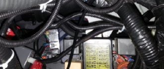
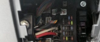
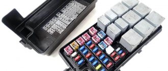
The relay and fuse box is also called the mounting block or black box. In the event of a car breakdown related to electrical equipment, the fuses and relays are first checked. If a fuse is blown, you must first determine the cause of its blown before replacing it.
Where are the fuses on the Priora?
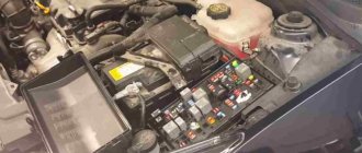
- The main mounting block of the Priora is closed with a lid and located at the driver’s left foot. To open it, you need to turn three latches 90° and unclip the lid.
- The fuse box is under the hood, which is located near the expansion tank.
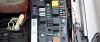
- Another mounting block, which is located near the left foot of the front passenger. To gain access to the fuses and relays, unscrew several screws with a Phillips screwdriver.
Below is a description of each fuse and relay block in order.
How to connect fog lights: what you need to know
A modern car is equipped with a number of lighting solutions to increase comfort and safety during vehicle operation.
As a rule, in addition to head optics and tail lights, many cars also have PTF on the front. The so-called fog lights do a good job of illuminating the road in poor visibility conditions (fog or rain), and are also an additional source of lighting in the dark.
Next, we will look at how to connect fog lights, the PTF connection diagram, as well as what features and nuances you should pay attention to during installation.
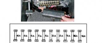
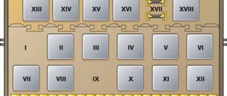
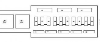
Priora fuse box diagram
| Fuse no. | Current strength, A | "Standard" and "Norm" | “Norma” with air conditioning and “luxury” |
| F1 | 25 | Engine cooling radiator fan | Reserve |
| F2 | 25 | Heated rear window | Mounting block, rear window heating relay (contacts). Electrical package controller, contact “10” of XP2 block. Rear window heating element. |
| F3 | 10 | Right headlight, high beam | Right headlight, high beam lamp. Instrument cluster, headlight high beam indicator. |
| F4 | 10 | Left headlight, high beam | |
| F5 | 10 | Sound signal | Mounting block, horn relay. Sound signal. |
| F6 | 7.5 | Left headlight, low beam | |
| F7 | 7.5 | Right headlight, low beam | |
| F8 | 10 | Alarm signal | Mounting block, alarm relay. Alarm sound. |
| F9 | 25 | Priora heater fuse | Reserve |
| F10 | 7.5/10* | Interior lighting, instrument panels, brake light | Instrument cluster, pin “20”. Brake light switch. Brake light bulbs. Interior lighting unit. Interior lighting. The door sill light on the right front door. Additional brake signal. |
| F11 | 10/20* | Wiper | Mounting block, high speed windshield wiper relay. Switch for cleaners and washers, contact “53a”. Wiper and washer switch, contact “53ah”. Heated rear window switch. Mounting block, rear window heating relay (winding). Windshield wiper motor. Rear window wiper motor (2171,2172). Windshield washer motor. Rear window washer motor (2171,2172). Airbag control unit, pin “25”. |
| F12 | 20/10* | Terminal 15 devices | Instrument cluster, pin “21”. Electrical package controller, contact “9” of block X2. Electromechanical power steering control unit, contact “1” of block X2. Reversing light switch. Reversing lamps. Parking system control unit, contacts “11” and “14”. |
| F13 | 15 | Cigarette lighter fuse Priora | |
| F14 | 5 | Left headlight, parking light, license plate light, trunk light | Side light lamps (left side) Instrument cluster, main light indicator License plate lights Trunk light Electrical package controller, pin “12” of block X2 |
| F15 | 5 | Right headlight, parking light | Side light lamps (right side) Glove compartment lamp |
| F16 | 10 | Terminal 15 ABS | Hydraulic unit, contact "18" |
| F17 | 10 | Left fog lamp | |
| F18 | 10 | Right fog lamp | |
| F19 | 15 | Seat heating | Seat heating switch, contact "1" Front seat heaters |
| F20 | 5/10* | Immobilizer control unit | Recirculation switch (switch on) Mounting block, relay for low beam headlights and parking lights (automatic lighting control system) Heater electric fan relay Automatic lighting control switch Windshield wiper and external lighting control unit, contacts “3”, “11” Automatic climate control system controller installation, pin “1” Automatic window cleaning system sensor (rain sensor), pin “1” |
| F21 | 7.5/5* | Rear fog lights | Light switch, contact "30" Diagnostic block, contact "16" Clock Automatic climate control system controller, contact "14" |
| F22 | -/20* | Reserve | Windshield wiper motor (automatic) Mounting block, windshield wiper relay and windshield wiper high speed relay, (contacts) |
| F23 | -/7.5* | Reserve | Windshield wipers and external lighting control unit, pin “20” |
| F24-F30 | Reserve | ||
| F31 | 30 | Electrical package control unit | Electrical package controller, terminal “2” of block X1 Electrical package controller, terminal “3” of block X1 Driver’s door module, pin “6” Threshold light of the left front door |
| F32 | Reserve | ||
* - for the “Norma” configuration with air conditioning and “luxury”
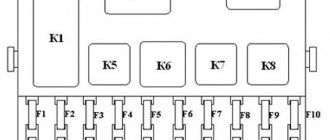
| Relay | "Norm" | "Norma" with air conditioning | "Lux" |
| K1 | relay for turning on the electric radiator fan of the engine cooling system | Reserve | Relay for turning on the low beam and side lights of the headlights (automatic lighting control system) |
| K2 | rear window heating relay | ||
| K3 | starter activation relay Priora | ||
| K4 | additional relay (ignition relay) | ||
| K5 | space for backup relay | ||
| K6 | windshield washer and wiper relay | ||
| K7 | headlight high beam relay | ||
| K8 | horn relay | ||
| K9 | alarm relay | ||
| K10 | Reserve | Fog light relay | |
| K11 | Reserve | Front seat heating relay | |
| K12 | Reserve | ||
Advantages of functional lighting equipment
Fog lights allow you to partially relieve the strain on the driver's eyes during a forced trip in difficult weather conditions. With their help, it is possible to achieve better illumination of the road surface. The greatest importance of headlights lies in the precise supply of light, which determines the illumination of the road.
Precisely adjusted devices illuminate up to 10 meters of space in front of the car, which is quite enough for safe driving in difficult weather conditions. Of course, for this you will need to adhere to a certain speed limit. The headlights are adjusted during the installation of the equipment. The quality of road lighting depends entirely on the setting of the angle of incidence of the light flux.
We recommend: Programs for chip tuning
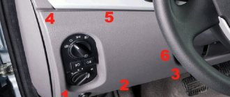
Location of Priora fuses under the hood
- F1 (30 A) – power supply fuse for the electronic engine control system (ECM);
- F2 (60 A) – fuse for the power supply circuit of the engine cooling system fan (power circuit), additional relay (ignition relay), rear window heating, electrical package controller;
- F3 (60 A) – fuse for the power supply circuit of the electric fan of the engine cooling system (relay control circuit), sound signal, alarm signal, ignition switch, instrument cluster, interior lighting, brake light, cigarette lighter;
- F4, F6 (60 A) – generator power circuit fuses;
- F5 (50 A) – fuse for the power supply circuit of the electromechanical power steering
Relay and fuse box for Halla air conditioner
- right electric fan power supply fuse (30 A);
- fuse for the power supply circuit of the left electric fan (30 A).
- right electric fan relay;
- additional relay (sequential activation of left and right electric fans);
- left electric fan relay;
- heater fan power supply fuse (40 A);
- compressor power supply fuse (15 A);
- heater fan relay;
- compressor relay.
Panasonic air conditioner relay and fuse box
- Heater fan maximum speed
- Right fan
- Fan sequential relay (low speed)
- Left fan
- Left fan fuse (low speed)
- Right fan
- Heater fan
- Compressor
- Heater fan
- Compressor
P O P U L A R N O E:
This short article will discuss how to make a fluorescent lamp based on electronic ballasts with your own hands for utility and technical rooms that do not require external beauty and exquisite design from the lamp.
The luminaire will be designed for tubular fluorescent lamps with a G13 base, 1200 mm long. These lamps are low in price and can illuminate a large area. Read more... How to save energy consumption on lighting and electric heating? How to save heat? Methods for real energy savings. Ways to reduce electricity consumption and energy costs. Application of energy-saving technologies. Read more…
You can buy a sofa, or you can save money and make a great sofa with your own hands! It's not difficult, see for yourself...
Additional mounting block Priora
- F1 (15 A) – main relay and starter interlock circuit fuse;
- F2 (7.5 A) – fuse for the power supply circuit of the ECU (controller);
- F3 (15 A) – Priora fuel pump fuse;
- K1 – main relay;
- K2 is the place where the Priora fuel pump relay is located.
Attention!
The relay and fuse diagram may differ depending on the configuration and production date of the vehicle. Current diagrams of the mounting block are presented in the operating manual for the date of manufacture of the vehicle ().
Let us remind you that on our website you can find detailed instructions for repairing the Lada Priora with your own hands.
Keywords: Lada Priora mounting block | Lada Priora torpedo
+134
Share on social networks:
Found an error? Select it and press Ctrl+Enter..
Errors when connecting fog lights
When installing a PTF for the first time, it is easy to make a mistake. It is better to familiarize yourself with them in advance so as not to allow them to happen by your own example.
The main problem is connecting the side lighting lamps to the wiring. The switch, like the wires used in this system, are not rated for the current drawn by the equipment. As a result, the wiring overheats and the protective insulation melts from the high temperature. Yes, the PTF will be activated when the side lighting is turned on at the same time. But the problem is that the equipment will not last long.
The second problem is the discrepancy between the installation parameters and those specified in the traffic rules. Traffic police officers have the right to check on site that the fog lights are working correctly. If the parameters are not met, the driver will have to pay a fine.
The third problem is the wrong choice of location for installing the button. The switch should be located no further than arm's length. Otherwise, you will have to reach for it, which risks getting into a traffic accident.
We hope our tips will help you connect and install fog lighting correctly!
Do-it-yourself connection of fog lights via a relay
Safety and comfort are the main qualities worthy of the attention of a car owner. If you care about yourself and each passenger, choose a fully equipped vehicle. Fog lights are not a mandatory component of the car: manufacturers often ignore this functional and useful element, wanting to reduce the cost of the cars they produce as much as possible. How to install and adjust fog lights will be discussed below.
Connecting fog lights
Any driver who has an idea of how to properly handle the tool can handle installing fog lights on a car. If you only know how to drive a car and do not touch the tools, it is unlikely that you will be able to equip your personal car with fog lights. In this case, it is recommended to contact the service station specialists. Before connecting the equipment, you will need to gather some tools and materials. You will need:
- set of wires for connecting fog lights;
- insulating tape;
- headlight block and relay;
- piercing and cutting instruments;
- fuse;
- power button.
Once the kit for connecting fog lights is assembled and ready for use, we proceed to connecting the fog lights. Below is the installation algorithm:
- First you will need to remove the central panel, where a pair of backlight bulbs for the furnace regulator are located.
- Run your hand along the wires until you can feel the two-pin connector, which will be useful during the connection process. You will subsequently need to secure the first contact to the relay to the connector.
- Take the first wire, then connect it to the stove light connector, while connect the second wire to the button
- Connect the wire to the relay, thanks to which you will be able to get a 12-volt circuit and pin 85 (as shown in the diagram below for connecting fog lights through a relay).
- Contact 87 will need to be routed to the battery under the car pedals. Also at this stage, a fuse is installed for a maximum current of 15 amperes. Try to place the fuse closer to the battery
- Contact 86 closes with the vehicle body.
- Each headlight has two wires (+ and -). Both positives coming from the headlights need to be connected, while the negative is connected to the body. The plus is connected to the corresponding battery terminal. Bring it to the relay so that the wires are invisible, and then connect it to the connector marked 30 in the diagram.
After you have managed to connect the fog lights, be sure to test them and check their functionality. If the headlights do not turn on, an error has been made.
Logical conclusion
If you are not looking for simple ways, you can try to disassemble the relay itself and check what is wrong with it. Perhaps the movable plate has become sour or the contact has come loose. Since the part is small, you need to be very careful not to bend anything. Using a small soldering iron and some fine-grit sandpaper, you can bring the relay back to life and gain valuable repair experience in the process.
Replacing the VAZ-2110 turn relay is quite simple and quick. There is absolutely nothing complicated, so it makes sense to do such work yourself. It does not require you to have any knowledge of electrical engineering. The relay itself may “fail” if its time is approaching. When the first signs of a malfunction appear, such as intermittent relay failure, altered click frequency, etc., it is better to stock up on a spare part in advance. This way, if necessary, you can immediately replace the VAZ-2110 turn signal relay.
In order to maintain the temperature regime of the engines, a fan is used for cooling; it is usually equipped with an electric drive. The options to turn on and turn off such a fan are controlled automatically. On cars with carburetor engines, the TM 108 sensor is used for this; on cars that have an injection engine, control is carried out using a controller.
Fan control from temperature switching sensors largely depends on the temperature settings of the sensors, which are indicated on the case. As the temperature rises until the sensors are triggered, the fans do not turn on, which requires checking that the sensor is working properly. To check, you should simply close the contacts on the sensors; if this happens, then the sensor should be replaced with a new one. If the fan does not work after shorting the terminals, then it is worth checking the integrity of the supply wires according to the diagrams.
The cooling fans of the VAZ 2110 with injection engines can be turned on by an electronic controller. The response temperature is built into the controller program and can range from 100 to 105 degrees. A malfunction of the temperature sensor is automatically recorded in the fan error code when the engine is running.
There are also malfunctions that make it impossible for the controller to recognize malfunctions; in this case, the fan cannot turn on. To check circuits and sensors, it is worth removing the connectors from the temperature sensors at a time when the engine is at full speed. In the event that the malfunction of the circuits can be checked by the integrity of the fuses, it is also worth checking the serviceability of the wires and relays according to the exact circuits.
Many tens are set to reduce the effort during maneuvers and turns.
For an accurate and quick test, it is worth bridging the output to approximately 87 relays. If after this the fan works, then connect the relay without removing it from the block using a test lamp, the relay will work and the fan will turn on immediately. In this case, the faulty controller or drive will need to be repaired.
If you don’t hear a click after turning it on, then you just need to change the relay. When installing jumpers between pins 87 and 30, the fan does not turn on. If there is power at this pin, this indicates that there may be some kind of malfunction of the engine fans.
Hello everyone, guys. In general, the rear PTFs do not light up. What could be the problem?
Comments 22
Mine didn't burn either. It turned out that the old owner took out the light bulb. Apparently they were needed a lot. It happens
Very funny) Based on the fact that I turned to the people for help, you can understand that I checked everything on my own! There are light bulbs and they work!
Dadada, there's a block under the panel on the ZPTF
I've looked all over, no(
They turn on when the low/high beam is on, this is me, by the way, since several of my friends put up with non-working PTFs until I told about the low beam, thereby making a colossal discovery for them)))