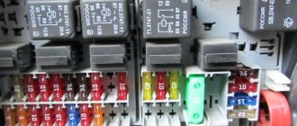
Oka brand cars are equipped with cylindrical type fuses. Total number of modules: 10 pieces, relays - switches 5 pieces.
Due to ineffective design and outdated technology, fuses often fail and melting elements burn out. The process of replacing with new ones is not at all complicated, but it is not always rational. Many car enthusiasts practice installing knife-type modules. This is a modern design with a melting element in the center.
Installation of blocks is no more difficult than cylindrical ones; every car enthusiast can cope with the task.
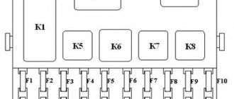
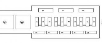
Fuse installation diagram
| Marking | Scheme |
| Fuse (1) / 15 | Stove heater |
| Fuse (2) / 10 | Fan activation sensor |
| Fuse (3) / 5 | Windscreen wipers |
| Fuse (4) / 5 | Carburetor solenoid valve |
| Fuse (5) / 15 | Turn signals. Alarm |
| Fuse (6) / 20 | Tail lights, oil pressure, battery |
| Fuse (7) / 20 | High beam, low beam, dimensions |
| Fuse (8) / 15 | License plate light |
| Fuse (9) / 5 | Power socket, interior lighting |
| Fuse (10) / 5 | Cigarette lighter |
The cost of the original fuse block assembly (hereinafter referred to as the BP) starts from 1,200 rubles. high-quality analogues from 800 rubles.
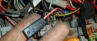
Replacing the turn signal and hazard warning relay
You will need a key "10"
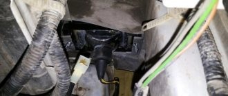
The turn signal and hazard warning relay, type 494.3747, is located behind the instrument cluster and is secured with a nut to the front panel stud.
The relay is marked on the cover of its housing.
14. Press out the two spring latches located on the sides of the instrument cluster from the inside of the instrument panel and.
15. . remove the combination from the instrument panel.
16. Unscrew the nut securing the speedometer cable and.
17. . Disconnect the speedometer cable from the instrument cluster.
18. Label the terminals and wire connectors.
19. Disconnect the pads from the instrument cluster and remove the combination.
20. Unscrew the relay mounting nut and remove the relay from the body front stud.
21. Disconnect the relay from the wire block (shown by the arrow). Install the relay in the reverse order of removal.
REPAIR When repairing the engine, use the following recommendations: - do not disassemble the engine before the warranty period expires (do not remove cylinder heads, oil sump, do not break fuel seals.
Checking the spark plug and adjusting the gaps between the electrodes PERFORMANCE ORDER 8. Inspect the spark plug. If there are cracks on the insulator, the threads or electrodes are damaged, the spark plug must be replaced. Light brown soot that evenly covers the bottom of the candle.
Open large picture in a new tab → Oka cars use a single-wire circuit for connecting electrical equipment, i.e., only one wire connects to all electricity consumers. The second “wire” connecting consumers to sources of electricity is the car body, or “ground”. This scheme allows you to significantly reduce the number of wires and simplify their installation. The negative terminals of the electricity sources are connected to ground. With this connection, the corrosion of metal body parts due to electrochemical corrosion is reduced.
The sources of electricity in a car are a generator and a battery connected in parallel. The rated operating voltage of electricity sources and consumers is 12 V. However, the voltage in the electrical equipment system, depending on specific conditions, can range from 11 to 14.5 V, and within these limits, consumers remain operational.
- 1) power system, including a battery and a generator with a voltage regulator;
- 2) the engine starting system, which includes the starter, starter relay and the corresponding ignition switch contacts;
- 3) an ignition system consisting of an ignition coil, a spark torque sensor, a switch, spark plugs, high voltage wires, an ignition relay and the corresponding ignition switch contacts;
- 4) a lighting and light signaling system that combines headlights, lanterns and corresponding switches and relays;
- 5) control devices with sensors;
- 6) additional electrical equipment, which includes a windshield and rear window cleaner and washer, a rear window heating system, a heater motor, a cigarette lighter and a sound signal.
The operation and activation of all systems is controlled by corresponding switches and relays. The supply voltage is supplied to most consumers through the ignition switch 31. The switched circuits for different key positions are shown in the table (see also Chapter 32).
The power circuits of those electrical equipment components whose operation may be required under any circumstances are always connected to the battery and generator (regardless of the position of the key in the ignition switch). These components include the sound signal 4, the cigarette lighter 45, the threads of the brake signal lamps in the rear lights 68, the license plate lights 70, the interior light 58 and the plug socket 11 for a portable lamp. Also directly connected to the power supply are the hazard warning circuits, side light circuits and the high beam headlight signaling circuit.
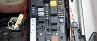
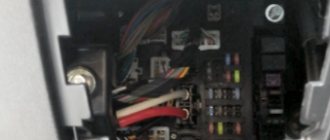
Replacing fuses on Oka
The PSU installation process is quite simple and intuitive. At the preparation stage, we check the availability of:
- Collar;
- Heads on "10";
- A new old-style power supply unit (cylindrical type) or a knife type, if the owner decided to upgrade;
- Additional lighting as needed if work is carried out in conditions of limited visibility.
Replacement steps:
- Place the car on a flat surface, open the driver's door wide;
- We wedge the rear row of wheels with wheel chocks and squeeze the parking brake lever. This is necessary for personal safety during work;
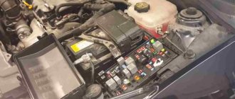
- Open the hood, unscrew the power terminals from the battery to prevent a short circuit in the on-board circuit;
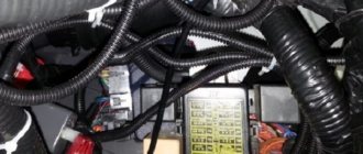
- We snap off the cover from the power supply unit and squeeze the plastic clips on the sides;
- Using a 10mm socket, unscrew the mounting bolts on the sides. We remove the power supply from the seat.
Next, we insert a power supply with knife-type fuses; if we are upgrading the equipment or identifying a faulty module, we replace it with a new one.
- Screw the bolts and put on the protective cover.
Oka oil pressure sensor photo where it is located
I decided to install an oil pressure gauge. For what ? just . In theory, everything is simple - you need an adapter (tee) to install an oil pressure sensor, a pressure sensor and the indicator itself (I used both and the third from a VAZ-2106). I bought everything for about 250 rubles (2002). When installing the adapter in place of the emergency oil pressure sensor (2101-3810600), the oil filter flange broke off!! Although I pulled with a regular open-end wrench without any extensions! The flange is made of aluminum alloy and is quite fragile. The next day I had to go to Moscow and buy this filter flange (1111-1012024) and its gasket 1111-1012030. The next day (I did everything in the evening after work) I began installing the flange. When installing the flange, I broke the “6” key. (the flange is secured with two M8x30 screws with a 6-point hexagon socket) Having decided that I had tightened it enough, I filled it with oil and drove off without looking. After 5 km, all the oil leaked out and we had to go back in tow. The next day I bought oil (Luxoil Extra 0W40 - the cheapest of the liquid ones, since it was heading towards winter), a high-quality set of hex keys, and a sealant gasket. Spitting on the advice of car manufacturers who do not recommend installing oil system parts on sealant, I installed a flange with a paronite gasket on the sealant, applying sealant on both sides of the gasket, only trying to spread the sealant in a thin layer and letting it dry longer so as not to get into the oil system. I started installing the adapter. This also has its pitfalls. Firstly, the engine compartment of the OKI is cramped, and installing an adapter with pressure sensors (for the pointer and for the warning lamp) is inconvenient - the mudguard gets in the way. And secondly, the main thing, it seems to me, is that there is a danger of these sensors-adapters-fittings touching the mudguard when the power unit vibrates - on bumps, etc. It is impossible to position the sensor so that the sensor is pointing upward at OKE - the filter gets in the way. Place it so that the sensor is pointing down? There is a danger of them touching the ground. Consequences? - see above . Therefore, I removed the mudguard (right mudguard 1111-2802022), with difficulty unscrewing the rusty screws, and installed the tee so that the sensor axis is directed approximately horizontally. After this, in my opinion, there was much less dirt in the engine compartment. And only the next day (the sealant polymerizes for a day) I filled it with oil and was on wheels.
From the oil pressure indicator I removed the useless wiring harness from OKE and the backlight and emergency pressure lamps. I installed female type terminals on the wires suitable for the indicator and connected them directly to the oil pressure indicator according to the following photo:
What does the pressure indicator show? In the speed range from idle to 3000. 4000 - approximately 4 atm, the overpressure increases approximately in proportion to the engine speed up to the maximum (8 atm at a speed of 5000. 6000). The readings vary somewhat, obviously depending on the temperature, voltage in the on-board network, type of oil and etc. Over the two years since the installation of the oil pressure indicator, the oil pressure at idle has decreased slightly - from 4.4.5 atm to 3.5. 4 atm. Moreover, when changing the oil for the last time, I filled in a mixture of Luxoil extra oils 0W40 -1.5 liters and 5W50 - 1 liter. — no changes in the pressure indicator readings. November 19, 2004
December 13, 2006 Over the past 2 years, the oil pressure at idle has remained almost the same - 3.5. 4 atm, the maximum at high speeds decreased slightly to 6.7.5 atm. The oil I currently use is Yukos System 0W-40, there is practically no difference compared to the previous Luxoil.
Installation of an oil pressure gauge on the OCU Installation of an oil pressure sensor on the OCU Installation of a device indicating oil pressure on the OCU Installation of an oil pressure indicator from the VAZ-2103 on the OCU Installation of an additional engine oil pressure gauge in the OCU Installation of additional devices on the OCU
How to identify a blown fuse
It is quite simple to assess the condition of cylindrical type modules, as well as knife type ones. In both cases, a melting element is laid in the center of the fuse.
As soon as the current exceeds the permissible value, the plate instantly melts, opening the contacts. A small black spot forms, which is evidence that the part is faulty.
The module is removed from its seat using special plastic tweezers. In life, an accessory is often lost, so it is practiced with your fingers. After replacement, we put the power terminals on the battery, start the engine, and test the system.
Models, characteristics, location
The designers did not borrow a starter from other VAZ models, but made a new one - for Oka engines. The impossibility of unifying starters for owners of this small car often results in problems, since the “native” starter is not a particularly reliable unit.
The main characteristics of model 39.3708 are as follows:
- Power – 0.9 kW;
- Current consumption – 230A;
- Weight – 5 kg;
This unit is mounted on the left side of the engine (in the direction of travel) above the gearbox, and the thermostat housing is located above it. Fixation is carried out with only two fasteners - a bolt and a nut, with which the starter is attracted to the clutch housing. This arrangement is convenient because you can dismantle the unit from the car without removing anything additional.
Common causes of fuse failure
- Systematic (periodic) power surges in the network;
- Oxidation of contacts on terminals, end switches;
- Damage to the insulating layer of the wiring, which leads to a “short-circuit” to ground, the car body;
- Damage to the body, impact, collision with oncoming traffic;
- Water entering the housing, condensation formation;
- Installing the module in a low current range;
- Unprofessional installation by the owner of the equipment.
Design
The ignition system of the VAZ Oka consists of only seven main elements:
- Auxiliary relay;
- Egnition lock;
- Circuit breakers;
- Switch;
- Spark moment sensor;
- Coil;
- Candles;
All elements are connected to each other by wiring.
Using the ignition switch, the driver controls the power supply to the system from a source - the battery, while the voltage passes through the auxiliary relay and fuses. The lock has three positions - “0”, in which all electrical consumers are turned off, “1” - voltage is supplied to the ignition system and a number of other devices, and “2” - current is supplied to the starter. This switching sequence ensures that the ignition system is activated at the moment the engine starts.
Spark torque sensor
The spark timing sensor is one of the main ignition components, since it sets pulses that are subsequently converted into a spark discharge between the spark plug contacts. This sensor is driven by the camshaft, which allows you to accurately set the timing of the spark in the cylinders.
The main working elements of the unit are the Hall sensor and a special screen with slots mounted on the drive shaft interacting with the camshaft. The interaction of these elements leads to the emergence of control impulses.
The adjustment is carried out by two regulators - vacuum and centrifugal, included in the design of the spark generation moment sensor.
Until 1989, Oka used a sensor of type 55.3706, and after that it was replaced by model 5520.3706.
Switch
The switch acts as a circuit breaker for the primary winding of the coil, using control pulses coming from the spark sensor. Circuit interruption in the switch is performed by the output transistor. The switch is completely electronic, without any moving elements, so the ignition system is contactless.
Several types of switches were installed on the VAZ-1111 and 11113 - 36.3734, 3620.3734, as well as HIM-52. The switch is installed in the engine compartment near the engine panel. It is secured with two bolts, so replacing the switch is quite simple.
Coil
Oka received a two-terminal ignition coil, which made it possible to remove the distributor from the design.
It is noteworthy that the high voltage in this coil is supplied simultaneously to both spark plugs. Moreover, due to the offset strokes in the engine cylinders, only one spark discharge is working, the spark on the second spark plug is the so-called “idle”.
Wires, spark plugs
All wiring consists of low and high voltage wires. The first ones are used to connect all the components up to the coil. These are ordinary wires of small cross-section, which is quite sufficient, since the voltage in the circuit up to the coil is low.
High voltage wires are used to connect the coil terminals to the spark plugs. For ease of connection, lugs are installed at the ends of these wires.
Recommendations for caring for BP
- Strictly observe the time intervals for technical inspection, even when the factory warranty has expired;
- Buy mainly original parts;
- Carefully check the catalog article numbers with the data specified in the vehicle’s operating manual;
- In the absence of experience, carry out repairs in certified workshops, where they provide a quality guarantee;
- To a lesser extent, use the services of unverified craftsmen, suppliers of parts and components.
Maintenance, repair
Of all the car’s electrical appliances, only power supplies require maintenance:
- Battery (periodic recharging using chargers, monitoring the level and density of the electrolyte);
- Generator (periodic check of drive tension, replacement of worn graphite brushes).
It is also important to monitor the condition of the wire insulation and prevent it from being damaged to avoid a short circuit. Oxidation of contacts often occurs at the wiring junctions, which can lead to failure of electrical appliances. Most of the electrical network components are maintenance-free and must be replaced if they fail.
Such elements include light bulbs, small electric motors, switches, relays, fuses, sensors
Most of the electrical network components are maintenance-free and must be replaced if they fail. Such elements include light bulbs, small electric motors, switches, relays, fuses, and sensors.
In the starter, generator, electric. In the heater and cooling system fan motors, mechanical breakdowns may occur - wear of bearings, bushings, brushes. All these components are repairable and it is often possible to restore their functionality by disassembling, troubleshooting and installing new parts to replace worn ones.
Differences between old and new PSUs
- There are no significant differences in functionality. Both blocks work equally efficiently. Another thing is that the modification of cylindrical type fuses is outdated and it is becoming more and more difficult to find components every day.
- Some creative motorists practice installing a power supply on Oka from Lada 10 - 15 models. Theoretically, such an upgrade is possible, but it will just require a lot of knowledge and experience in assembling electrical circuits.
- You need to re-solder the entire power supply, five relays - switches. Loop the parts onto one board and fix it to the frame under the dashboard. To ensure safe work, use the services of certified workshops and auto electricians.
- Remember that unprofessional intervention is more likely to harm than improve the efficiency of a particular unit.
- The average service life of an old-style power supply is 60 – 65 thousand km. The service life of blade type fuses is 80 – 90 thousand km. Depending on operating conditions, quality and professionalism of assembly, the interval can be increased to 5 - 10 thousand km.
- When purchasing parts, carefully check the catalog numbers with the data in the operating instructions for the technical device.
Installation and repair of a starter in an OKA car (VAZ-11111)
Skoda octavia fuses (Skoda Octavia) a5: where are they located, replacement
Like any internal combustion engines of passenger vehicles, the power units of the Oka car modifications 1111, 11113 are started using a starter - a power electric motor with remote control. The task of this unit is to spin the crankshaft to create the necessary conditions for ignition of the air-fuel mixture.
Models, characteristics, location
The designers did not borrow a starter from other VAZ models, but made a new one - for Oka engines. The impossibility of unifying starters for owners of this small car often results in problems, since the “native” starter is not a particularly reliable unit.
It is noteworthy that Oka’s power electric motors were produced by several manufacturers. The most common is the unit with the factory index 39.3708 (KZATE Samara plant), which we will consider in the future. Also, the VAZ-1111 was equipped with Belarusian-made components (1111-3708010-5) and Slovenian ones - AZE-1517.
The main characteristics of model 39.3708 are as follows:
- Power – 0.9 kW;
- Current consumption – 230A;
- Weight – 5 kg;
This unit is mounted on the left side of the engine (in the direction of travel) above the gearbox, and the thermostat housing is located above it. Fixation is carried out with only two fasteners - a bolt and a nut, with which the starter is attracted to the clutch housing. This arrangement is convenient because you can dismantle the unit from the car without removing anything additional.
The starter on the Oka is a commutator electric DC motor. Its main components are:
- Stator with field windings;
- Brush holder (brush assembly) with 4 graphite brushes;
- Anchor;
- Bendix (drive gear with freewheel);
- Solenoid relay with drive plug;
- Lids;
All elements are assembled into a single structure and secured with coupling bolts.
The stator due to the passage of electrical energy through its windings, ensures the emergence of an electromagnetic field. The second magnetic field is created by the armature winding. Electric current is supplied to it through graphite brushes to the commutator, to the plates of which the ends of the armature winding are soldered. The magnetic fields generated around the windings lead to the rotational movement of the armature.
On one side of the armature shaft there are splines on which a bendix is mounted, consisting of a gear and an overrunning clutch. Bendix has the ability to move along the shaft, and due to the spline connection, rotation is transmitted to it.
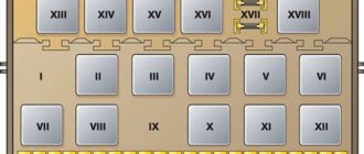
Electrical diagram of VAZ-11113 with symbols
The electrical circuit of the VAZ-11113 does not differ significantly from the VAZ-1111. The car was equipped with a modernized version of the power unit and some components that had virtually no effect on the electrics.
Contactless ignition diagram indicating the main elements and connecting wires
Contactless ignition VAZ-11113
List of elements:
- 1 - control relay;
- 2 — ignition switch with contact group;
- 3 - protective fuse;
- 4 - controller;
- 5 - sensor that determines the moment of spark supply;
- 6 - common ignition coil;
- 7 - candles.