Unexpected reasons for non-working PTFs on the VAZ-2110
The most common cause is a blown fuse.
But we will return to it later. There is still a lot that is still unknown in the design of foglights, relays, switches and lamps. For example, a possible reason for the failure of fog lights could be a completely unexpected breakdown.
First of all, we check the bulbs themselves; you can get to the left one through the hood.
On some versions of the VAZ-2110, a PTF from the Avtosvet plant (Kirzhach) was installed with a socket for the H1 lamp. Stock lamps are not the best quality and they do not like sudden changes in temperature.
It is quite difficult to get to the right fog lamp through the hood; it is easier to remove the headlight itself by unscrewing the screws.
During sudden cooling, when leaving the garage in winter, for example, or after turning off the headlights, the contact leg of the lamp bulb simply fell off the conductor . At the same time, visually the halogen lamp looked absolutely intact. It was enough to apply a plus directly to the leg itself, and the lamp would light up. The fault was due to poor-quality resistance welding, and it is almost impossible to detect the cause without a detailed examination of the lamp itself and its dismantling.
Of course, it is impossible to provide for all failure options, but we will consider the most common ones.
One fog light on VAZ-2110 does not light up
There may be plenty of options here. Apart from damage to the lamp itself or its filament, the picture is as follows:
- Fuse . When correctly installing PTF on the ten, as a rule, they use the scheme presented above. F4 or F14, is responsible for the operation of each lamp . They are located in the mounting block, which is located in the niche of the front panel to the left of the driver. When replacing a fuse, we do not use bugs or jumpers, but only new fuses.
The front right fog light is fuse F4, the left one is F14, both are 10A.
We find the wires with blocks coming from the headlights and check their condition.
Two fog lights do not light up at once
If this happens, it is impossible to allow two lamps or two fuses to burn out at once. Most likely, the reason should be looked for elsewhere:
- Oxidation of contacts on connector Ш1 in the mounting block . We remove the connector and evaluate the condition of the contacts. Just in case, check fuses F1, F14, F4.
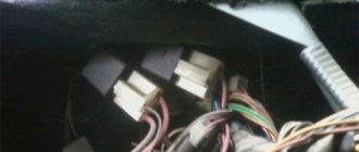
The connectors are located on the reverse side of the mounting block.
The PTF relay can simply hang on the wires.
General recommendations
In addition, we check the presence of voltage in the fog light circuit, finding out where the plus is connected.
And the power can be taken either from the ignition switch or from the side lights switch, which is undesirable, since you can leave the PTF on along with the lights on, and this will lead to battery discharge. Good luck with your search, bright and smooth roads!
Fog lamp relay VAZ 2110: differences in factory configuration
Did you like the article? Follow our channel for new ideas of useful car tips. Subscribe to us in Yandex.Zen. Subscribe.
Like any modern car, the VAZ “ten” was constantly improved during the process of mass production. However, all modifications concerned the originally installed components and assemblies of the vehicle. For example, front fog lights were not included in the external lighting of the car, but both a relay and a PTF control button were installed in the electrical circuit.
For reference: in the rear block headlights, the side light lamp had a second filament, which served as fog lights. It was activated by a button on the front panel and made it possible to improve the visibility of the car in conditions of poor visibility for other road users driving behind.
Requirements for installing PTF
How legal is it to independently install fog lights and will it not cause problems when meeting with traffic police officers? Let's consider excerpts from the standards by which PTF is established by the manufacturer (GOST 8769–75 and GOST 41.48–2004):
- Number of lanterns – 2 pcs.
- Installation height – not lower than 25 cm from the road surface, but lower than the low beam lights.
- Installation in width - no further than 40 cm from the side lights.
- The vertical coverage angle is 5-10 degrees.
- The lighting angle of the road surface (horizontal) is 45-55 degrees.
- PTFs are turned on only together with the side lights.
Historical reference
The four-door VAZ 2110 sedan was produced by the Volzhsky Automobile Plant from 1995 to 2007. And unlike the usual Lada cars, the model was positioned as a higher-class car.
In particular, the car was equipped with:
- electronic engine control system (ECM);
- diagnostic unit (on-board computer);
- galvanized metal was actively used in body parts;
- the body was painted using a new, more progressive technology.
Features of electrical equipment
In addition, the automaker carried out factory preparation for installation of:
- electric windows;
- power steering;
- fog lights in the front bumper.
Note! The ECM was installed even on the VAZ-2110 with a carburetor power system and differed from later models with a fuel injection system.
Electrical diagram of VAZ 2110
For reference: on models with a carburetor, the button for turning on the rear fog lights had an intermediate position (fixation), thereby acting as a kind of contact protection.
The advent of fuel injection and electronic ignition systems on automobiles has significantly increased the requirements for electrical components. The current increased and many devices required relays for protection. (See also the article Installing fog lights on a Grant: features.)
That is why, starting in 2000, on models with an electronic system, it was necessary to better protect the contacts. Therefore, a relay was installed in the PTF control circuit between the button in the cabin and “+”. And the button itself was replaced with a dual-mode one.
Note! The two-mode non-fixed operating algorithm provides that the button acts as a switch on the relay circuit. Those. closes the contacts with a low current, thereby avoiding the passage of high voltage through its contacts.
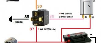
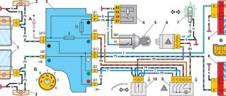
The illustration below shows:
- fog lights (front);
- PTF turn-on relay with pins 30, 85,86 and 87;
- mounting block to which the relay is connected;
- exterior lighting switch on the instrument panel;
- button for turning on fog lights;
Also indicated by letters:
- to the power source (generator and battery);
- to the instrument lighting switch button.
Fog lights VAZ 2110
Owners of cars of the tenth family of different years of production found themselves in an unequal position, because, firstly, they had different electrical circuits:
- Rear PTF activation button with locking and without protection relay (in models up to 2000);
- A button without fixation and with a relay in the PTF activation circuit (models from 2000 onwards).
Secondly, on the first models the installation of PTF in the front bumper was not provided. Those. If the owner has a desire, he needs to resolve all installation issues himself. Or buy a modified bumper, the price of which is too high. (See also the article Installing fog lights on a Chevrolet Lacetti: features.)
Note! When installing PTF in the bumper, be sure to order the production of stickers for the headlights. This film will protect the glass from flying stones and plant branches.
How to connect fog lights with your own hands
Before directly installing the headlights, their location is determined. In the case of the VAZ 2115 car, the bumper already has standard holes for installing additional lighting fixtures. Similar ones can be cut in the bumpers of VAZ 2113 and VAZ 2114.
There is no need to spoil the appearance of the bumper - fog lights are easily installed on special brackets. Many PTF kits contain special decorative plugs that add attractiveness and neatness to the installed headlights and facilitate the installation process.
Installation and connection algorithm
- Installation of a power button in the car interior. In the case of the VAZ-2114, the place for the button is on the left side of the driver on the front panel. However, its placement can be arbitrary - the main thing is that it is convenient for the driver to drive the car. Often, PTF power buttons are installed instead of plugs on the control panel.
A PTF activation button is installed in the cabin in a place convenient for the driver.
The power button is connected, chips are connected to it
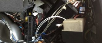
Under the hood there is a block to which the PTF relay will be connected
The wiring harness connects to the fuse box
The PTF relay is located in the engine compartment
PTF connection diagram
Wiring diagram for connectors and terminals of fog lights
The functionality of the entire connection can be checked by turning on the side lights - only then will the fog lights work.
Fog lights only function when the side lights are on
After completing the installation of the PTFs on the car, they only need to be adjusted correctly. The flow of light should not blind drivers in the oncoming lane.
PTF service
At the same time, many owners of the first ten cars do not know where the fog lamp fuse is located. And if it malfunctions, they don’t know how to replace it.
On models after 2000. fuses are grouped in a single block.
Their technical parameters are as follows:
- The rear PTF fuse is marked F20 and is designed for a current of 7.5A;
- Fuse F4 at 10A is responsible for protecting the front right fog lamp;
- Fuse F 14 at 10A is responsible for protecting the front left fog lamp.
Fuses and relays VAZ 2110 - 2112, electrical diagrams
If some devices on your VAZ 2110 or VAZ 2112 , fuses or relays may be to blame. At the very least, the first thing you need to do is check them, and then draw some conclusions regarding the malfunctions.
Correct diagnosis of many electrical problems will allow you to accurately determine the cause of the inoperability of a particular unit. To find out what the fuses and relays of the VAZ 2110 - 2112 are responsible for and how to find the right one, read this article.
As in many other cars, in the VAZ-2112 and VAZ-2110, when the engine is turned off, the devices are powered directly from the battery. When the engine is running, voltage is supplied to the devices from the generator, which simultaneously charges the battery. If the current exceeds the permissible value or a short circuit occurs, the circuit fuse will blow. Powerful electrical appliances are connected via relays.
Buy quality spare parts for VAZ-2110
Often, the acquisition of outright “Chinese” products leads to breakdowns. This does not apply to fuses and relays as much as it does to chassis and engine system parts. That is why it is strongly recommended to purchase spare parts in specialized stores for classics. You can order online, which allows you to choose the manufacturer and delivery time.
Of course, this applies more to foreign cars, for which you cannot find spare parts in every store. But sometimes it’s difficult to find any part for the “top ten”. Spare parts for the VAZ-2110 such as relays and fuses cost pennies, and there is no need to save on it. Always carry spare fuses with you.
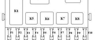
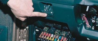
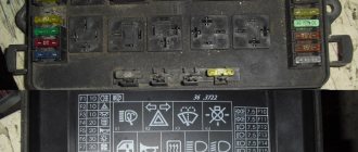
Fuse and relay box
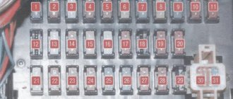
The fuse and relay box is located on the left, lower part of the instrument panel. It is accessible by pressing the button and folding the lid down. To remove fuses, there are special non-conductive pliers in the upper left part of the mounting block.
1 - K5 - high beam relay . If the high beams in two headlights do not work, check this relay. If one of the high beam headlights does not work, check fuses F3 and F13, as well as the lamps and the high beam switch.
2 - K4 - low beam relay . If the low beam in both headlights does not work, check this relay. If only one low beam headlight does not work, check fuses F2 and F12, as well as the lamps themselves and the light switch.
3 - K1 - lamp health control relay.
4 - non-conductive tweezers for removing fuses.
5 - power window relay . If your power windows stop working, check this relay. It could also be in fuse F5, or in the window lift drive system itself. To get to the mechanism, you need to remove the door trim. Check the electric motor, the appearance of the gears and the absence of binding of the mechanism.
6 - K3 - turn signal and hazard warning relay . If your turn signals or hazard lights do not work, check this relay and fuse F16, as well as the turn signal lamps themselves and their switch.
7 - starter relay . If the car does not start and the starter does not turn, check this relay. It could also be a dead battery, as well as the starter mechanism itself.
8 - backup fuses.
9 - fog lamp relay . If the fog lights do not work, check this relay and fuses F4 and F14. Also check their connection diagram, the serviceability of the wiring and connectors, as well as the lamps in the headlights and the power button.
10 - K2 - windshield wiper and washer relay . If your windshield wipers or windshield washer are not working, check this relay. Also check the wiper motor, washer pump and washer fluid level in the washer reservoir.
11 - K7 - rear window heating relay . If the heating does not work and the rear window fogs up, check this relay and fuses F8 and F9. Also check the connection contacts to the terminal points of the heating elements (at the edges of the glass at the rear pillars). If everything is in order, but the heating does not work, the issue may be in the wiring (the wires are frayed or something else).
12 - K6 - add. relay, ignition relay . If your ignition does not turn on or is having problems with it, check this relay. This relay protects the ignition switch contacts from burning. Also check the ignition switch itself and the contact group.
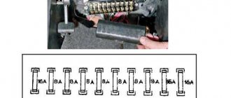
13 - row of fuses F1-F10
14 - row of fuses F11-F20
Signs of problems with the PTF relay
The main reason why it may be necessary to replace the fog lamp relay is the malfunction of the latter. But don’t rush to conclusions and rush to buy a new relay. By itself, it is a fairly reliable design, and in combination with a small number of consumers and low current in the circuit, this device rarely fails.
Therefore, before replacing the PTF relay, you should check other elements in the fog lamp circuit, namely:
- light bulbs;
- wiring;
- power button;
- circuit breakers.
The latter should be given special attention, since two fuses are responsible for protecting the fog lights, designated in the general block as F8 and F9. In some cases, they may be serviceable, but due to oxidation of the contacts they will not pass electric current. In this situation, they should be carefully removed and their contact surfaces, as well as the contact surfaces of the sockets in the common block, should be cleaned. Very often, after this procedure, the headlights begin to work.
A sure sign that the fog light relay is working properly, and the cause of the problem should be sought in the wiring or fuses, is a situation when only one of the headlights does not light up. Checking and, especially, replacing the relay in this case is pointless.
If, after checking, all the links in the fog light chain are in good condition, but the headlights themselves still refuse to turn on, you should proceed to checking and, probably, replacing their relays.
Circuit breakers
Now let's see which fuses are responsible for what in the same mounting block. I will also give the main reasons for troubleshooting.
F1 (5 A) - license plate lighting lamps, dashboard lighting, side lights on the panel, trunk lamp, left side lights . If any of the listed lamps do not work, check this fuse, as well as the lamps themselves and their contacts. If everything is in order, check the headlight switch button.
F2 (7.5 A) - low beam in the left headlight . If both low beam headlights do not work, also check relay K4 and the lamps themselves. It could also be the light switch and its contacts.
F3 (10 A) - high beam in the left headlight . If both high beam headlights do not work, check the K5 relay, the lamps themselves and the high beam switch knob.
F4 (10 A) - front fog lamp on the right side . If both fog lights do not work, check relay 9 and the headlight bulbs themselves, as well as the switch and its contacts.
F5 (30 A) - window lift motors . If the power windows do not work, check this fuse and relay 5. In winter, check if the windows are frozen, warm them up and clear them of ice if necessary. It could also be the window lift motor, its mechanism and gears; in order to get to it, you need to remove the trim of the desired door.
F6 (15 A) - portable lamp fuse.
There may also be problems with the cigarette lighter. To check, unplug the cigarette lighter from the connector. If this fuse stops burning, then the problem is in the cigarette lighter.
F7 (20 A) - engine cooling fan, sound signal . If the cooling fan does not turn on and the engine overheats, check this fuse. Also check the operation of the fan motor by connecting it directly to the battery. It could also be the coolant temperature sensor or thermostat.
F8 (20 A) - heated rear window (element) . If the heating does not work and the rear window fogs up, check this fuse, fuse F9 and relay K7. Also check the contacts on the terminals of the heating elements, check the wiring, sometimes the wire frays. It could also be the heating switch and its contacts.
Front harness diagram for VAZ 2114 injector
In this case, even if you forget to turn off the fan, it will stop working after turning off the ignition. It is this circumstance that allows this mechanism to create significant force.
On the door trim, in place of the hole for the manual drive, there is a plug. This occurs due to attempts to open frozen windows. Then you need to squeeze out the clip, not the casing. The secret to the reliability of the device is the simple kinematic diagram of the transformation of the rotation of the electric motor shaft into the translational movement of the glass mounting bracket.
We measure the button with a caliper and transfer the dimensions onto thick cardboard. It is this circumstance that allows this mechanism to create significant force. The letter “A” in the diagram indicates the wires going to the power supply of the circuit, and the letter “B” indicates the wires going to the side lights.
F12 at 7.5 A right low beam. Sometimes vehicles are equipped with rear fog lights, the purpose of which is to improve the vehicle's visibility when driving in fog. This is especially true for the cable mechanism. The inability to ventilate the air in the cabin or reduce the temperature in the summer often reduces the composure that is so necessary for a person behind the wheel. Installation and connection of air suspension control buttons for VAZ 2114
PTF relay VAZ 2110
Relay Description:
K1 – lamp health monitoring relay; K2 – windshield wiper relay; K3 – relay-interrupter for direction indicators and hazard warning lights; K4 – headlight low beam relay; K5 – headlight high beam relay; K6 – additional relay; K7 – relay for turning on the heated rear window; K8 – backup relay (not installed on vehicles of the VAZ-2110 family);
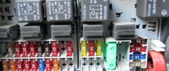
Numbering of plugs in the connecting blocks of the mounting block and the colors of the wires connected to them
Diagram of the VAZ-2110, 2111, 2112 mounting block.
Old-style mounting block VAZ-2110, 2111, 2112. Location of fuses and relays.
Table of circuits protected by fuses on the VAZ 2110
To maintain the temperature regime of the VAZ 2110 engine, an electrically driven cooling fan is used. Switching the fan motor on and off is controlled automatically. The circuit diagram for switching on the cooling fan of the VAZ 2110 on carburetor and injection cars is different. On cars with a carburetor engine, TM-108 is used for this, and on cars with an injection engine, control is carried out by a controller. When controlling the fan, whether the fan is turned on depends on the temperature setting of the sensor, which is indicated on the body. If the fan does not turn on when the temperature rises to the sensor response temperature, you must first check the serviceability of the sensor. To check, just close the contacts on the sensor and if it turns on, you need to change the sensor. If after closing the terminals the fan does not work, then the cooling fan switching circuit and the integrity of the fuse need to be checked.
The circuit for switching on the cooling fan of a VAZ 2110 with an injection engine is powered by an electronic engine control controller. The response temperature in this case is set in the controller program and can be from 100 to 105 degrees. C. If the temperature sensor malfunctions, an error code is entered into the controller’s memory and the fan turns on while the engine is running. But there are malfunctions in which the controller does not recognize the malfunction and the fan may not turn on when the temperature reaches above 105 degrees. C. In this case, to check the circuit and sensor, it is necessary to remove the connector from the temperature sensor while the engine is running. If the circuit is working properly and the sensor is malfunctioning, the fan will turn on and turn off when the connector is returned to its place. If the circuit malfunctions, it is necessary to check the integrity of the fuse, the serviceability of the relay and wires, according to the circuit. For a quick check, you need to bridge terminals 30 and 87 of the fan relay, located in the heater shaft on the passenger side. If the fan works, without removing the relay from the block, connect the case and pin 86 of the relay with a test lamp, the relay should work and the fan should turn on. In this case, the controller or the wire connecting the relay to pin 46 of the controller is faulty. If you do not hear the characteristic click of the relay turning on, and a positive signal is supplied from the main relay to pin 85 of the relay, and if there is a click and the fan does not turn on, change the relay. When installing a jumper between pins 30 and 87 does not turn on the fan, check the integrity of the fuse and the presence of power at the fan terminals. If there is power on one terminal and no power on the other, this indicates a possible malfunction of the fan motor.
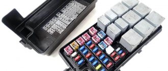
The mounting block is presented in the form of a black box. Unlike airplanes, you can gain access to a car “black box” at any time the car owner needs. This unit is of great importance because it combines all the electrical components of your VAZ 2110.
In simple terms, the mounting block is a console with a board inside. It contains fusible links - fuses. Plus there are relays there.
The design is designed in such a way that the driver has the opportunity to independently replace a failed component. To do this, remove the broken fuse and insert a new one in its place. They cost pennies, but can seriously affect the performance of the equipment.
Where is the turn signal relay on the VAZ-2110
If the turn signal does not work, then the first thing to do is check the fuse box, since this is where the reason often lies. A fuse could simply have blown or a relay has failed, which happens less often, but still happens.
Finding this block on the “ten” is quite simple; it is located next to the hood opening lever. The breaker relay is located in socket K-3. It is responsible for the operation of turn signals and hazard warning lights. A blown fuse is extremely easy to find; it is usually identified visually and replaced with a new one. There is nothing complicated here. If there are problems with the relay, then in most cases there is no point in repairing it. It is much easier to buy a new one and be sure that it will not fail in the near future.
Location
Since AvtoVAZ engineers tried to do everything so that car owners would not have problems replacing relays and fuses, it would be stupid to come up with a clever arrangement. Therefore, finding them is not difficult.
- The main unit is located to the left of the steering wheel;
- You will find the first additional block in the dashboard inside the niche, directly behind the main mounting block;
- The second additional block is located in the same place, only on the opposite side.
We will get acquainted with each block separately so that you do not have any confusion when searching for one or another fuse.
On injection engines with 16 and 8 valves, the location of the MB is identical, so the instructions are equally relevant for owners of both versions of the dozen.
Main MB
Relays and fuses are located here. Let's look at their descriptions in more detail and separately.
VAZ 2110 fog lamp relay - main features and design
As you know, the operation of most electrical devices in a car is regulated using special units. In this review, we will look at one of them - the VAZ 2110 rear fog lamp relay, especially since the system is very simple, and you can understand its operation without special education in this field. This part has been installed on models since 2000; before that it was not installed.
Comparison of six and four contact relays - the difference is obvious
Repair and replacement of fog light relays
First, you should make sure that the VAZ 2114 rear fog lamp relay is faulty.
This can be done using a multimeter - just turn it on to measure direct current with a limit of 20 volts and check the presence of voltage at the outputs:
- 1 and 3;
- 2 and 3;
- 6 and 3 (with the engine running).
If there is no voltage at these contacts, we can clearly conclude that the relay has failed.
The check can be performed in another, simpler way - just listen carefully and turn on the rear fog lights. If the relay is working properly, it will definitely make a characteristic loud click.
Repairing a failed relay should begin with a careful inspection of its contacts, because most often they are the cause of the malfunction. Thus, outlets covered with a film of oxides should be carefully cleaned using sandpaper or a cloth moistened with kerosene. You should also check the wires that go to the relay legs - sometimes they break right at the terminal due to vibration - they should be soldered in place.
If the main supply wires of the relay break along the way, you can solve the problem by reconnecting the wiring from pins 1 and 2 to pin 6. This procedure must be performed with the engine turned off and with the negative terminal removed from the battery - otherwise a short circuit can occur.
If after all the measures listed above it was still not possible to fix the fog lamp relay, then all that remains is to replace it with a new one (of a similar model). To do this, simply disconnect the wires from the outputs of the old relay and connect them to the legs of the new relay in exactly the same sequence.
How does the device in question work?
The main features of this relay can be considered the following:
- The type of device is normal open, the type of block is six-pin; to ensure convenience and simplify the connection, the numbering of the contacts is present on the body of the product.
- The system is assembled in such a way that the contacts close by trigger. In simple terms, the design functions like this: when you press the button, the system turns on, when you press it again, it turns off.
- The most important feature of the device is that it functions only when there is voltage on two additional contacts. It is thanks to them that the button automatically turns off when the car’s ignition is turned off.
- The relay can be designed to operate in systems with a current not exceeding 20A .
This is what the circuit of the relay we are considering looks like
Important! As noted above, the unit began to be installed in cars since 2000, so you should not believe experts who claim that the relay was not installed on this model. They just haven’t encountered this version of the system, and since products fail quite rarely, such a question does not arise so often.
What you need to know about the device
In order to properly connect the system or replace a failed element, you need to know several important features, which we will consider. Many motorists turn to car repair shops, while the work can easily be done with your own hands, especially since the price of this simple repair is for some reason high.
Relay replacement
Sometimes the rear fog lights simply stop working, and if everything is in order with the bulbs and the button, then most likely the reason lies in the failure of the relay.
In this case, the sequence of actions is as follows:
- First of all, you should purchase a new relay 23.3777; if you previously had a problem purchasing this modification, now you can order it in the online store, and they will simply send you the necessary spare part by mail or send it via express delivery service. It is at least unreasonable to disassemble the system before purchasing a new unit.
- Next we need to find our device. The question of where the rear fog light relay is located in the top ten is one of the most common, so we will pay special attention to this nuance. First of all, the right cover of the center console (that is, on the front passenger side) is removed. It is attached to several self-tapping screws, so this type of work will not cause difficulties.
- After removing the cover you will see the ECU connector and a whole fuse and relay block, but this is not what we need. Our unit is located on the top left; if you look at the structure, it is attached separately to the center console bracket, which is why it is often not noticed when checking the unit located below.
- Replacement is very simple: unscrew the fixing screw, remove the assembly, disconnect the connector, put a new relay in its place, after which everything is assembled in the reverse order.
If you decide to install a relay in a model where it is not provided for by the design, then you will additionally need a block for six contacts
Important! It is not recommended to replace the relays with regular four-pin ones, since you need to redo the entire system, and this requires certain knowledge and skills.
A service that is popular these days, such as the production of stickers for headlights, is also justified on fog elements, helping to extend their life. The main thing is that it does not affect the brightness of the light and does not create any interference.
Advantages of this system
So how does the operation of a six-pin assembly differ from the usual and widespread four-pin version?
Everything is very simple and clear:
- The main advantage of the option under consideration is the fact that when the system is de-energized and the ignition is turned off, they turn off and do not turn on when the ignition is turned on, that is, they must be turned on again. This system allows you to protect the battery from discharge in cases where you forget to turn off the fog lights.
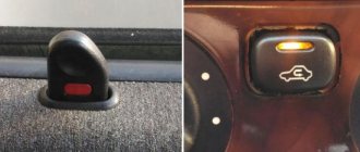
- The system is turned on and off using a button by pressing it once, which is also very convenient. In order to see that the fog lights are working, there is a special indicator on the button, so you can glance at the console and see that you need to turn off this type of lighting. The button is shown in the photo below.
The indicator on the button is another useful little thing to increase comfort.
How to make your own 6-pin header
Sometimes the problem arises with the block - in some regions it is difficult to find, but you can get out of the situation, simple instructions will help you with this:
- First, you need to purchase a “mother” contact strip.
- Next, two pieces of three contacts are cut off and placed one on top of the other, resulting in the configuration we need. First, you should attach them in this position to make sure that nothing is in the way.
- After this, you need to fix the block; the best option is to put on a heat-shrinkable tube of the appropriate size and then heat it up - this way we get an almost complete structure, firmly connected into one unit. A simpler solution is simple electrical tape, but still the first option is preferable and looks much better.
Relay 23.3777 is responsible for the operation of the rear fog lights
The video in this article will help you understand some of the nuances of the topic under consideration even better. It will clarify some important points even better and allow you to perform work at the highest level.