Starter relay VAZ 2111
The purpose of the relay is to effectively activate the starter, which later powers the vehicle's engine itself.
This is explained by the appearance of a magnetic field in the electromagnetic coil located in the relay housing. The starter's operating time is sufficient to start the engine. Electrotechnical is engaged in the production of starter relays for VAZ 2111 cars. The latest technologies and achievements in the field of science and technology are used in production. The company's team is a friendly team of true professionals who use all their knowledge and achievements to obtain the best results. The relays produced by our factory are the best, high-quality products from a modern manufacturer.
Device and principle of operation
The device is assigned the following functions: engaging the drive gear with the flywheel gear of the engine crankshaft, as well as providing power supply to the starter motor. At the moment when the ignition key is installed in the “starter” position, voltage is applied to the holding and retracting windings of the traction relay. This happens through an additional relay. After closing the contacts of the traction relay, the retractor winding system is switched off. In this case, the traction relay should operate at a voltage no higher than 9 V and at a temperature of 15–25 ºС. Otherwise, this may indicate a malfunction either in the drive or in the relay itself. To check the condition of the drive, the starter should be disassembled and thoroughly inspected. Defects found during the inspection must be subject to mandatory replacement.
Modern variations of the device require the presence of two windings: the main and holding windings. An additional or so-called holding winding is used to reduce the supplied current to the relay at the moment of its operation. An additional winding can reduce current consumption, saving battery capacity.
The new modern starters are additionally equipped with a non-separable traction relay, which is easily replaced with a new one in case of malfunction or breakdown. Old style starters are characterized by a relay that can be disassembled and the fault repaired.
All the work of the plant’s design bureau is aimed at improving the products produced. VAZ 2111 starter relays were no exception. The production of electrical equipment undergoes constant, regular modernization, which has already become an integral part of the company's policy. The introduction of the latest technologies and achievements of modern science contributes to the fact that the plant’s products are absolutely competitive. It fully complies with all existing Russian and world standards. In addition, all products produced by the plant are subject to mandatory testing, and only after that are sent to the market.
Electrotechnical Chelyabinsk, an enterprise with a long history and rich experience, brings to your attention an electromagnetic starter relay for the VAZ 2111, which can be purchased wholesale and retail. The plant provides all existing and necessary guarantees for
products from our factory, and a controlled quality system is guaranteed by state certification.
Where is the fuse for the fuel pump?
A common failure associated with the fuel system is that the fuel pump fuse blows. In this case, power is not supplied to the pump, and the fuel pump itself stops pumping gasoline into the main line. As a result, the car stalls, the pump does not buzz in the gas tank after turning the ignition key, and the engine does not start.
Why do fuel pump fuses blow?
A fuse is a small element whose task in the design of electrical circuits is to melt in the event of an overload. The device melts and the current-carrying circuit opens.
Using the example of a solution from the popular VAZ Priora model, we can superficially examine the design and operating principle of the fuse. The device is small, the outer casing is made of plexiglass.
There is a conductive element inside. Such an element is based on several plates, which are made of different materials. Between these plates there is a special low-melting material. Electricity passes through this material, which allows the fuse to be an integral part of the electrical power circuit of the fuel pump.
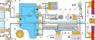
Fuses and relays VAZ 2110 - 2112
Fuses and relays VAZ 2110 - 2112, electrical diagrams
If some devices on your VAZ 2110 or VAZ 2112 , fuses or relays may be to blame. At the very least, the first thing you need to do is check them, and then draw some conclusions regarding the malfunctions.
Correct diagnosis of many electrical problems will allow you to accurately determine the cause of the inoperability of a particular unit. To find out what the fuses and relays of the VAZ 2110 - 2112 are responsible for and how to find the right one, read this article.
As in many other cars, in the VAZ-2112 and VAZ-2110, when the engine is turned off, the devices are powered directly from the battery. When the engine is running, voltage is supplied to the devices from the generator, which simultaneously charges the battery. If the current exceeds the permissible value or a short circuit occurs, the circuit fuse will blow. Powerful electrical appliances are connected via relays.
Fuse and relay box
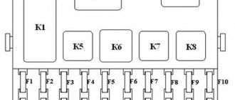
The fuse and relay box is located on the left, lower part of the instrument panel. It is accessible by pressing the button and folding the lid down. To remove fuses, there are special non-conductive pliers in the upper left part of the mounting block.
1 - K5 - high beam relay . If the high beams in two headlights do not work, check this relay. If one of the high beam headlights does not work, check fuses F3 and F13, as well as the lamps and the high beam switch.
2 - K4 - low beam relay . If the low beam in both headlights does not work, check this relay. If only one low beam headlight does not work, check fuses F2 and F12, as well as the lamps themselves and the light switch.
3 - K1 - lamp health control relay.
4 - non-conductive tweezers for removing fuses.
5 - power window relay . If your power windows stop working, check this relay. It could also be in fuse F5, or in the window lift drive system itself. To get to the mechanism, you need to remove the door trim. Check the electric motor, the appearance of the gears and the absence of binding of the mechanism.
6 - K3 - turn signal and hazard warning relay . If your turn signals or hazard lights do not work, check this relay and fuse F16, as well as the turn signal lamps themselves and their switch.
7 - starter relay . If the car does not start and the starter does not turn, check this relay. It could also be a dead battery, as well as the starter mechanism itself.
8 - backup fuses.
9 - fog lamp relay . If the fog lights do not work, check this relay and fuses F4 and F14. Also check their connection diagram, the serviceability of the wiring and connectors, as well as the lamps in the headlights and the power button.
10 - K2 - windshield wiper and washer relay . If your windshield wipers or windshield washer are not working, check this relay. Also check the wiper motor, washer pump and washer fluid level in the washer reservoir.
11 - K7 - rear window heating relay . If the heating does not work and the rear window fogs up, check this relay and fuses F8 and F9. Also check the connection contacts to the terminal points of the heating elements (at the edges of the glass at the rear pillars). If everything is in order, but the heating does not work, the issue may be in the wiring (the wires are frayed or something else).
12 - K6 - add. relay, ignition relay . If your ignition does not turn on or is having problems with it, check this relay. This relay protects the ignition switch contacts from burning. Also check the ignition switch itself and the contact group.
13 - row of fuses F1-F10
14 - row of fuses F11-F20
Circuit breakers
Now let's see which fuses are responsible for what in the same mounting block. I will also give the main reasons for troubleshooting.
F1 (5 A) - license plate lighting lamps, dashboard lighting, side lights on the panel, trunk lamp, left side lights . If any of the listed lamps do not work, check this fuse, as well as the lamps themselves and their contacts. If everything is in order, check the headlight switch button.
F2 (7.5 A) - low beam in the left headlight . If both low beam headlights do not work, also check relay K4 and the lamps themselves. It could also be the light switch and its contacts.
F3 (10 A) - high beam in the left headlight . If both high beam headlights do not work, check the K5 relay, the lamps themselves and the high beam switch knob.
F4 (10 A) - front fog lamp on the right side . If both fog lights do not work, check relay 9 and the headlight bulbs themselves, as well as the switch and its contacts.
F5 (30 A) - window lift motors . If the power windows do not work, check this fuse and relay 5. In winter, check if the windows are frozen, warm them up and clear them of ice if necessary. It could also be the window lift motor, its mechanism and gears; in order to get to it, you need to remove the trim of the desired door.
F6 (15 A) - portable lamp fuse.
There may also be problems with the cigarette lighter. To check, unplug the cigarette lighter from the connector. If this fuse stops burning, then the problem is in the cigarette lighter.
F7 (20 A) - engine cooling fan, sound signal .
If the cooling fan does not turn on and the engine overheats, check this fuse. Also check the operation of the fan motor by connecting it directly to the battery. It could also be the coolant temperature sensor or thermostat.
Finding the fuel pump relay and troubleshooting
As you know, in order to start any process, be it mechanical or electrical, you need a source of energy.
And the relay thus represents a kind of trigger mechanism, because its work is to connect the contacts located inside, which close when exposed to electric current. The following two tabs change content below.
- About the expert:
Fan-avto All my life I have been surrounded by cars! First, in the village, already in the first grade, I was rushing around on a tractor through the fields, then there was JAVA, then a penny. Now I am a third-year student at the Polytechnic Faculty of Automotive Engineering. I work part-time as a car mechanic and help repair cars for all my friends.
If we personally consider the VAZ-2112 fuel pump relay, then there are certain specifics in its operation. It also happens that many car enthusiasts simply do not know where exactly this relay is located, and how to correct the malfunction when it fails.
Principle of operation
Almost all relays that are mounted on Russian cars are identical. For the most part, they differ in the number of contacts with five versus four, and the latter, as a rule, does not have a central input.
The current strength, measured in Amperes, is also almost the same and is about 30 - 40A.
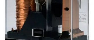
>
The relay in the photo is 30 Ampere.
The relay is connected to the network using a plastic block (plug - approx.), and when the electric current reaches the coil inside the relay and the magnetization process begins, it then closes and the circuit is connected.
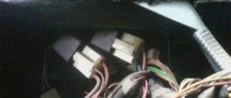
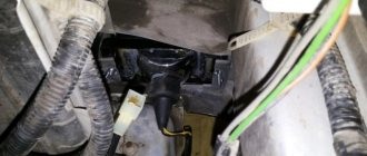
Relay in additional fuse box
Location of the additional relay unit inside the car
The fuel pump relay is located on the left side of the front passenger's feet, where three relays and three fuses are located next to each other.
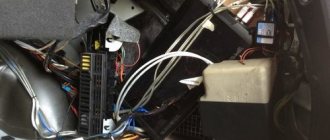
After dismantling, we put it aside
The fuel pump relay is located exactly in the middle under the number “5”. The fuse number “3” is also located nearby.
Additional block
Functionality check
In order to check the fuel pump fuse, you just need to inspect it and, if necessary, replace it with a known working one.
There are several methods to check the fuel pump relay:
- The easiest way is to replace the old relay with a known good one.
- If you don’t have one at hand, you can use a regular multimeter.
Improvement of the starter blocking relay and contact protection in VAZ 2110, 2111, 2112
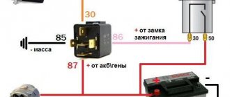
Based on the operating experience of VAZ (first the classic 21011, then 2111), it has long been noticed that very often the ignition switch contacts (ISC) that control the starter solenoid relay burn out and become unusable. The current through these contacts reaches 20A. We have to replace the entire contact group. So I decided to fix this problem immediately on a new machine, without waiting for it to appear. A common option is to install an additional relay in the power circuit and control it with 3Z contacts. Everything is simple, but as it turned out, this is not at all necessary, because... you can use an existing starter interlock relay, retaining its original functions completely. As analysis of the circuit showed, the starter lock relay is powered from +12V from the main relay of the ECU, and the minus is supplied from pin 50 of the ECU (January 7.2), and is controlled by an “open collector” key in the ECU. When the ignition is turned on, the ECU sets the “low level” (shorts to ground) on contact 86 of the locking relay. The relay is activated, completing the circuit between the ignition switch and the starter solenoid relay. When you turn the key ZZ from pin “50”, 12V is supplied to the starter solenoid relay. As soon as the engine starts, the ECU removes the signal from pin 86 of the relay, it is de-energized, breaking the circuit, and thereby blocking the starter. The blocking works! Fig. 1 shows a fragment of the circuit in the basic version, and Fig. 2 - after modification. As you can see, the changes are minimal: 1. The pink-black wire is disconnected from the pin. "85" and isolated; 2. The power wire from the ignition switch is connected to pin. “85” relay 3. Added a power wire (30 cm) from the connector from which the CB is powered (2-pin connector to the front harness) - with a cross-section of at least 4 mm2, connected to the pin. 87 relays. Now the power circuit is controlled through a relay, and the current through the 3Z contacts does not exceed 0.2A. The modification was completed in 2009. Pros: minimal alterations, no need for another relay, saving space in the control unit Cons: not found in 6 years.
Below is a fragment of the diagram.
Well, the final option. Starter relay and additional relay for “unloading” the ignition switch contacts
The final diagram with unloading of the lock contacts along the ignition circuit
But that's not all! The next weak point: the power contacts of the starter solenoid relay. Due to high currents, they receive an even greater electrical load, and as a result, erosion. You can protect them from sparking, especially when opening, by connecting one powerful diode in parallel with the starter and the control winding of the solenoid relay. The essence of the modification is to suppress the “self-induced emf” - the main cause of contact burnout. I used fairly common diodes, KD2998 - high pulsed and direct current, and they had sufficient quantities on hand. You can use rectifier diodes from computer power supplies rated for a forward current of at least 30A. The diodes are placed in 2 layers of heat shrink and connected directly to the starter on short wires. The connection diagram is shown.
Elimination of voltage drop in VAZ 2110, 2111, 2112
Much has been written about the rather unsuccessful and dim rear lights of the VAZ-2111. This problem becomes especially relevant
Which fuse is responsible for the fuel pump VAZ
An electric pump fuse that fails is one of the most common failures associated with the fuel system. If power to the fuel pump stops being supplied, it does not pump fuel into the common line. The result: a stalled car, no buzzing in the gas tank after turning the key, and other problems.
Where is
The location of the fuse on modern cars is indicated in several special blocks. This decision is due to the fact that the availability of spare elements is completely justified. This reduces the risk of fire several times. In addition, this makes it possible to localize, albeit conditionally, possible short circuit locations. The circuit is divided into several sections, from one special block to another, thereby creating a clear separation: if a short circuit occurs in one section, it is not transmitted further.
On VAZ cars, fuses can be found in a special block under the hood and in the passenger compartment. Other places are also possible, for example, near the fuel pump, under the glove compartment, under the stove, etc. Basically, the location of the fuse depends on the model of the dashboard.
Starter relay VAZ 2110
In 1995, a completely new model, the VAZ 2110, rolled off the assembly line of the Volzhsky Automobile Plant. During the production process, it, like all models of the plant, was subject to various modifications. The engine starting system has also undergone changes. In 2003, the so-called starter relay began to be installed on cars of this model. What is this relay for? Where is it installed, and is it possible to install such a device if it is not provided? The answers to these questions are outlined in the article below.
What is a starter relay?
When talking about the starter relay among car enthusiasts, for some reason everyone clearly believes that the starter relay is precisely a solenoid relay. Such a relay is designed to change the position of the freewheel, which extends a special gear to subsequently start the engine. Once the engine starts, the relay is de-energized and the clutch returns to its original position, pushing the gear back in. This approach allows you to preserve the service life of the gear and not damage the car starter.
However, the starter relay is not a solenoid relay. The starter relay is a device of a completely different purpose and design. This is an electronic relay that connects to the starter power circuit and, depending on the speed and duration of rotation of the crankshaft, closes and opens this circuit.
When you turn on the starter, the first action is to activate the controller, which connects the starter relay, thereby turning it on. The condition under which this action will be performed is the crankshaft speed corresponding to less than 500 rpm. If within 20 seconds of the starter operation the engine does not start, that is, the speed does not exceed 500, then the relay opens and turns off the starter power circuit.
Starter connection diagram 29.3708 for VAZ 2108, 2109, 21099 cars: 3 comments
In this article, we will be much more interested in the second relay, which is responsible for the operation of the starter, namely the retractor. Also look at how much charge the battery has. And now he saves 35 rubles a year on gasoline!
Replace the core. Register on site 2. We conducted a little investigation and came to the following conclusions, yes, from the factory on VAZ cars, a starter relay was installed. If the starter does not turn off, then the relay is missing. Most often, such a start indicates wear of the teeth on the Bendix gear or the teeth of the engine flywheel.
To understand why a starter solenoid relay is needed, let’s look at the engine’s operation schematically. Other possible schemes are no different from the one described. We conducted a little investigation and came to the following conclusions, yes, from the factory on VAZ cars, a starter relay was installed. The problem is not constant, this can happen once a week, maybe every other day. VAZ starter relay wiring diagram. SOLVING THE PROBLEM WITH THE IGNITION SWITCH VAZ 2110 2111 2112
VAZ 2110 starter solenoid relay: where is it located, do-it-yourself replacement
Many owners of the domestic “ten” are faced with a situation where it is impossible to start the engine using the starter. Moreover, they do not blame the starter itself, but the relay.
But when the process of searching the engine compartment begins, they fail to find the starter relay on the VAZ 2110. It is not surprising that numerous websites, forums, and social networks regularly publish questions of approximately the same nature - where is the starter relay on a VAZ 2110.
How it works
Plus, when the contacts on the traction winding are closed, the starter motor is supplied with power from the battery. The contacts are washed out, the blocking is activated, due to which the retractor winding is “cut out”.
The retractor is controlled directly from the ignition switch. Plus it plays the role of starter protection. The fact that the relay will require an impressive amount of current leads to gradual wear of the contacts in the contact group.
This can be noticed by the unclear start of the power unit; periodically the starter may not operate or may rotate the engine slowly. You can solve this problem on your own.
Examination
First, it is recommended to perform a check. Now we will tell you how to check the starter solenoid relay on a VAZ 2110.
- We get to the starter itself.
- To the left and slightly below the battery, directly next to the gearbox, is the starter we are looking for.
- The starter and relay, as you remember, are located in a common housing with two terminals. Be sure to ensure that these terminals do not short out.
- Check the voltage limit on the solenoid relay. The maximum value is not higher than 8V.
- Make sure that the temperature at activation does not exceed 25 degrees Celsius. If the number is higher, then don't expect the starter and his defense to perform effectively.
- Some breakdowns are determined visually, so inspect every centimeter of the device in detail and disassemble it.
Dismantling
The dismantling process cannot be called difficult; even a beginner can handle it. Just follow the given instructions.
- Disconnect the negative cable from the battery.
- Remove the air filter.
- Disconnect the set of wires that go to the retractor.
- Remove the nut responsible for securing the tip of the power wire. To do this you will need a 13 key.
- Now it is the turn to dismantle the nuts that hold the starter. Here you need a larger key - 15 millimeters. But if the top one unscrews without any problems, then it will not be easy to get to the bottom one. But it will have to be done.
- Remove the starter.
- Remove the nut of the lower terminal of the solenoid relay and disconnect the wiring.
- Unscrew the relay mounting bolts using a size 8 wrench and remove it completely.
Typical breakdowns
Now let’s figure out how to check the starter solenoid relay on a VAZ 2110. It must be carefully inspected after dismantling.
This unit is characterized by certain breakdowns, which we will talk about.
- The fastening is loose or the nuts responsible for fastening the wire end are completely loose. Everything is simple here, as you understand. You just need to tighten the fasteners.
- Oxidation has formed on the windings, connections or wiring. If everything is not too serious, you can simply clean the contacts. In case of serious oxidation, it is better to replace them with new ones.
- The power supply circuit has breaks. Again, you don’t need to come up with anything fancy, just replace the chain.
- The armature exhibits idle operation or slow operation. Just replace the armature and that's it, problem solved.
- Check the short circuit of the turns of the two windings using an ohmmeter.
Replacement
In fact, it is theoretically possible to repair the relay. But in reality this is rarely justified in terms of financial and time costs.
A much simpler and more rational solution is replacement. The procedure will not take much time, but the unit will definitely work properly and reliably. It is unknown what the result of the repair will be.
If the relay is incorrectly repaired, this can lead to blocking the start of the power unit. The cost of repairing such a problem is much higher than buying a new high-quality relay.
Proceed with caution, keeping an eye on each item you take apart and put back together. Clean some contacts, if necessary, tighten loose fasteners. Whatever one may say, as the car is used, it shakes violently and vibrates, which leads to the banal loosening of nuts and bolts. What's most interesting is that this often leads to a whole range of problems. Therefore, make sure that each individual fastener is securely fastened.
Location and principle of operation
ATTENTION! A completely simple way to reduce fuel consumption has been found! Don't believe me? An auto mechanic with 15 years of experience also didn’t believe it until he tried it. And now he saves 35,000 rubles a year on gasoline! Read more"
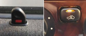
The location of the relay cannot be the same for all car models. This is directly related to the design of the machine, its make and model. However, in most cases, this is the area near the ICU (injection control unit) or under the dashboard, near the mounting block. On injection cars, the relay is usually installed in the driver’s left foot area, under the dashboard.
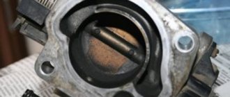
The relay, despite the structurally successful circuit, can deteriorate and fail. Signs of a defect in this case are actions that are unusual for work or their complete absence. Here, for example, is how the pump is controlled according to the diagram.
- After the ignition is triggered, the PTH sends a signal to the fuel pump, which is activated for two seconds. This time is enough to build pressure in the rail (direct fuel injection).
- The relay will then start clicking, turning off the fuel pump.
- The next phase of work is associated with two conditions: rotation of the starting device and autonomous operation of the power plant. The PTH sends a shutdown signal to the pump as soon as the engine stops.
Relay in the engine compartment
On certain brands of cars, the relay also solves the problem of the crankshaft speed limiter. For example, if the engine voltage is too high, approaching the maximum line, the electric pump is turned off. The signal is sent by the relay, indicating that the fuel supply to the engine has stopped. Accordingly, the amplitude of shaft rotation decreases, and the fuel pump turns on again.
There are also cars in which the relay is not activated after the ignition is turned on. Once you open the driver's side door, it starts working. This solution is effective as it allows for quick start of the power unit. Pressure is created much earlier. The fuel pump already pumps fuel into the system in advance.
Relay output diagram
In fact, the relay is a small black box that resembles a US plug. Each of the device pins has its own marking.
As mentioned above, on some cars the relay can perform other functions.
- Lambda probe heating. It turns on differently on all relays. For example, on one it can be used together with a fuel pump, and on the other it can be connected via a separate transistor. On older versions of the car there was no lambda probe, but when the pump was running, the current could be wasted.
- For turning on the starting nozzle. This happens when the engine is started cold. The PF operates for the same amount of time as the starting device, and also directly depends on the temperature of the internal combustion engine. The specific operating time of the PF is determined by the relay that receives information data from the control unit. For example, if the temperature of the power plant reaches 60 degrees Celsius, the PF is activated for only 1 second or even less, and if the engine is cold - up to 10 seconds.
| 31 | weight |
| 30 | +12V constant (regardless of ignition) |
| 15 | +12 with ignition on |
| 50 | +12 when the starter is working |
| T.D. | signal from the ignition system |
| TF | engine temperature signal from the injection control unit KE |
| 87 | power supply to the fuel pump |
| 87H | oxygen sensor heating |
| 87V | turning on the starting injector |
Starters VAZ 2101-2107
Any car, whether ours or a foreign one, has the ability to break down. Car breakdowns can be divided into two types: mechanical and electrical.
Mechanical, for example, includes breakdowns associated with moving parts of the car. And electrical breakdowns imply malfunctions with electrical consumers such as the starter, radio, and so on. And quite often, drivers began to encounter electrical breakdowns. Basically, the most common electrical breakdown is the failure of the car starter. After all, a huge load is placed on the starter when starting the car. And if the car is not yet new, then the failure of the starter increases many times. But let's take a closer look at the starter design. A starter is a kind of electric motor with high current consumption. After all, in order to crank the crankshaft and start the engine, you need to have enormous power. Let's figure out what the starter electric motor consists of.
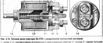
The electric motor housing contains an armature consisting of a winding and a shaft. The ends of the winding in turn receive power from the brushes. There are 4 brushes in the starter electric motor, all brushes are connected into one wire that comes out of the electric motor housing. There are 2 magnets glued to the walls of the case. And when power is supplied to the winding through the brushes, this in turn creates a magnetic field and causes the armature to rotate. A necessary component in the starter is the bendix, which engages the crankshaft when the car is started, and when the engine starts, it disengages. There is also a retractor relay installed on the starter housing. The solenoid relay is a kind of coil that draws in the core and closes the contacts, thereby supplying (+) to the starter. Let's also take a closer look at what the solenoid relay consists of.
The solenoid relay consists of a contact group, a coil and a core. From the contact group on the outside of the solenoid relay there are 2 copper threaded studs; a permanent plus, which comes from the battery, is screwed onto one stud, and the plus from the starter is screwed to the second stud. The minus for the electric motor and the retractor goes along the body. There is also a control contact on the solenoid relay that comes from the ignition switch. That is, it turns out that when you turn the key in the ignition switch to the second non-fixed position, voltage is supplied to the control contact on the solenoid relay. When voltage is applied to the control contact, the coil begins to retract the core and thereby close the 2 contacts together. After which voltage is supplied to the starter, and it begins to rotate the armature, which is connected to the bendix.
When the car starts and you release the key, the power from the supply contact disappears and the contacts on the solenoid relay open. As you can see, everything is very simple. Let's now move on to identifying the specific fault. For example, you turn the key, but the starter does not turn. Possible malfunctions:
- The coil of the solenoid relay has burned out;
- The armature winding of the electric motor burned out;
- The electric motor brushes have become unusable;
- Poor contact to the solenoid relay or to the electric motor;
- There is no power to the solenoid relay or to the electric motor;
- There is no power to the control contact on the solenoid relay;
- The retractor clicks, but the starter does not turn.
Let's look at the detailed steps to check the above faults.
Check whether your battery is well charged, you can find out from the on-board computer, or if you do not have a battery, then using a multimeter (the voltage must be at least 10.2 V).
Move the multimeter to the voltage measurement position, and connect one probe to the stud to which the battery cable goes. And the second probe goes to the battery negative. This way you will check whether the voltage to the solenoid relay is suitable.
If voltage is supplied to the solenoid relay, but when turning the key it does not make a characteristic click. Then you need to check whether the positive is coming from the ignition switch. To do this, you need to remove the plug from the control contact on the solenoid relay. And connect the pin with the wire from the battery to the control contact on the solenoid relay. If the relay clicks, then the problem is in the wire coming from the ignition switch.
If the relay clicks, but the electric motor does not spin. It is possible that the contact between the retractor and the electric motor wire may oxidize. To check this, switch the multimeter to dialing mode. And connect one probe to the stud, and carefully pierce the wire insulation with the other probe so that the probe comes into contact with the wire core. This way you will know whether the contact between the pin and the wire has oxidized.
If everything is fine with the voltage supply to the electric motor, then you will have to disassemble it and find out the reason. An electric motor can have two breakdowns related to the winding and brushes. It is almost impossible to check the condition of the winding due to the low resistance. But the condition of the brushes can be assessed by their size. If the brushes are already worn out, then the contact from them will be poor. The solution is to replace the entire contact group, since it is not that expensive compared to the price of a new electric motor.
Replacing a starter on a Lada family car:
- Remove (+ and -) from the battery.
- Remove the control plug from the solenoid relay.
- Unscrew the nuts from the studs of the solenoid relay and remove the wires.
- Unscrew the nuts holding the starter. (Depending on the model there may be 2 or 3)
- Remove the starter and repair or replace it.
Install in reverse order.
Here are the main problems and their solutions. As you can see, if you correctly identify the part that has failed, you can save money on purchasing an assembled starter. After all, fortunately, nowadays there is a huge selection of auto parts from different manufacturers.
It’s up to you to decide whether to buy an assembled starter for a VAZ, or to gain invaluable experience in repairs. We, in turn, guarantee you a huge selection and always low prices!
Article rating:
Starter relay VAZ 2111 Link to main publication
Related publications
- Mazda 3 Ball Joints: Key Suspension Element
Malfunctions
In most cases, they are related to tension problems. Power is not supplied to the electric pump and this causes the engine to stop. Another option that happens quite often is that the pump is noisy and does not turn off after creating the required pressure level. Both cases deserve detailed consideration.
DIY relay replacement
So, if there is no power, the pump will not pump. The fuel rail is empty, and in systems with direct injection, starting the power plant is impossible. In the second case, when the pump does not turn off, we are talking about sticking contacts of the device. The charge is wasted on the constant rotation of the motor.
It is noteworthy that on some models, auto engine starting is possible even if there are malfunctions. This can be achieved due to a successful circuit that allows the device to operate while the starter device is rotating.
Relay malfunctions primarily include its natural wear and tear. As they say, nothing lasts forever; every detail has its own resource.
If the part is relatively new, then you should look for problems:
- if water gets inside the box, then traces of rust will be visible;
- in a factory defect (happens);
- in capacitors that have failed;
- in violation of the electrical circuit;
- in KZ.
RTN on the diagram
Replacing the relay is easy. You can do this yourself.
- Find the relay. If it is located under the dashboard, remove the center armrest, remove the part of the panel in which the ashtray and cigarette lighter sit.
- Next, the plastic protection is removed.
- The clamps securing the relay to the body are unscrewed.
- A new relay is installed in place of the old one.
Video: fuel pump relay Opel Vectra
If you notice deviations in the operation of the relay, do not wait. It is better to immediately, without delay, check and replace. Remember that if it is not in order, the engine will not be able to start due to the fuel pump stopping.
Tired of paying fines? There is an exit!
Forget about fines from cameras! An absolutely legal new product - NANOFILM, which hides your license plates from IR cameras (which are installed in all cities). More details
- Absolutely legal (Article 12.2.4).
- Hides from photo and video recording.
- Installs independently in 2 minutes.
- Invisible to the human eye, does not deteriorate due to weather.
- 2 year warranty
Location of VAZ 2114 fuses in the main block
On the fourteenth Lada model, in 90% of cases two types of mounting blocks are used. The location of the internal parts and the pinout of the fuses of the VAZ 2114 are not significant, but they are different. Therefore, it is most convenient to consider both options separately.
Note!
Some modifications of the vehicle may be equipped with other module designs. You can find out the name of the variety on the inside of the lid.
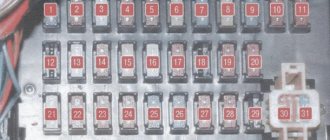
Fuses for VAZ 2114 injector (block 3722010-60)
The module contains fuse links and automatic circuit breakers. All elements are marked in order.
Main unit relay
- 1 – Head optics wiper switch;
- 2 – Contact insert breaker of the turn signal and hazard warning signal mechanism;
- 3 – Responsible for the proper operation of the windshield wipers;
- 4 – Fuse for monitoring stop lines and vehicle lighting;
- 5 – Power supply to electrical accessories (window regulators);
- 6 – Horn control, main circuit;
- 7 – Power line for heating the aft glazing;
- 8-9 – respectively, control of high and low beam head optics.
Decoding the fuse diagram of the VAZ 2114 head unit
- F1 – fog lights at the rear of the car;
- F2 – control circuit for turn signals and hazard warning switch;
- F3 – power supply to the interior and luggage compartment lamps, also ignition indication, ECM;
- F4 – fuse for the aft wind window heating relay circuit; the portable lamp contact is also energized here;
- F5 – fuse for the signal of the VAZ 2114 and the head fan of the cooling system;
- F6 – is fully responsible for the electrical package circuit;
- F7 - standard fuse for the VAZ 2114 heater, also responsible for electric drives for the windshield washer, glove compartment lighting and headlight wipers;
- F8/9 – fusible links responsible for the front fog lights;
- F10/11 – backlight for the left and right sides, respectively, also responsible for illuminating license plates, cigarette lighter, and instrument panel;
- F12/13 – light fuse for VAZ 2114 for low-range mode on the right and left sides, respectively;
- F14/15 – similarly for the long-range lighting mode on both sides of the car separately;
- F16 - VAZ 2114 instrument panel fuses are responsible for indicating sensors and device status.
Main relays and fuses for VAZ 2114 in block type 3722010-18
A more modern modification, installed on cars since 2010. Here the arrangement of elements and fusible links is more thought out. Thanks to a more logical layout, individual elements are easier to access.
At the same time, not only the location of the fuses is different, their functionality and area of responsibility are also changed.
Head relays
- 1 – optical wipers;
- 2 – is responsible for the switch for turn signals and emergency lights;
- 3 – cleaners for the front part of the car glass;
- 4 – module for serviceability of lighting elements and backlight;
- 5 – control of the electrical package circuit;
- 6 – horn power supply;
- 7 – power conductors for heating the rear window;
- 8-9 – circuit breakers for high and low beam head optics, respectively.
- F1 – headlight cleaner contact connectors, also refers to the sprinkler tank motor activation valve;
- F2 – turns and opens the alarm when activated;
- F3 – illumination of the interior space of the cabin, power supply circuit for the side lights of the rear part of the vehicle;
- F4 – cigarette lighter fuse for VAZ 2114, overload protection for the heating element of the rear window, this also includes a portable lamp;
- F5 – VAZ 2114 fan fuse is responsible for cooling the antifreeze, also responsible for the horn;
- F6 – power supply for windows and electrical accessories;
- F7 – control lines for the front and rear sets of headlight and windshield washers – a complete circuit of equipment, this also includes the glove compartment lighting;
- F8/9 – front fog lights for the right and left sides, respectively;
- F10 – fuse for the lighting of the VAZ 2114, the cigarette lighter, the instrument panel indication, the engine compartment lighting, also the left side of the side light;
- F11 – separately for the right side of the side lights;
- F12-15 – power supply for head optics, complete lighting set;
- F16 – fuse for VAZ 2114 instruments, also coolant temperature indicators, voltmeter.
How are the blocks separated in the machine?
The main type of block is placed in the most convenient place for the driver. In this version of the VAZ it is located on the left side of the body directly at the steering wheel. Easy access to the unit is provided using a built-in button located next to the car's headlight control.
2 backup units with relays are located separately in the right and central parts of the console just behind the dashboard. One of the fuses shown below in the diagram will be located at a distance from the rest of the list - it can be found in a special compartment behind the main fuse block, next to the mounting block. To timely repair electrical equipment on a VAZ-2110, you need to learn how to quickly determine the location of a blown fuse, and also know which elements of the car its failure will affect.
Advice: very often one burnt valve can lead to replacing the vacuum booster on a VAZ-2110. That is why it is important to check not only the general condition of the fuse, but also the parts that interact with it, for example, the injector.
Doesn't work, sound signal (beep) doesn't sound. Reasons. Scheme. Let's figure it out))
the sound signal malfunction
.Principle of operation. Possible reasons. Diagram. My VKontakte group.
Sometimes you can restore functionality by spraying Signal WD 40 or a similar composition. On cars that have two horns installed, they usually differ in tone, low and high. If one signal fails, the second cannot fully supply the required power and therefore requires replacement.
Generally, many signals are equipped with a screw to adjust the tone, and if there is rattle, chopping and other unwanted sound effects, you can use the adjustment to achieve a suitable sound. In addition, with their help you can move the acidified membrane, thereby restoring the effectiveness of the signal. 1) check the presence of incoming ground or voltage on the signal itself (on old systems there is a plus constant, and the signal is controlled by a minus). If there is a plus and a minus that occurs when you press the beep
, replace the signals themselves (the signals are not reset, and if they do not work, they must be replaced);
2) Check the supply voltage (fuse, relay , mounting block); 3) a button on the steering wheel (contacts, adjustment of switches and triloger), the presence of mass on the steering column;. the sound signal appears spontaneously when turning the steering wheel: It should be noted that on some models and PRIORAS the signals are placed in the anti-theft system (signals about opening or closing doors, acts as a security system and emergency signals), and some reasons for the signal failure may be related to it . ,