Home• Volkswagen• Golf 2• Electrics
Relay and fuse block Golf 2 on models produced before 07.1989.
Diagram of the Volkswagen Golf 2 mounting block on models produced from 08.1989.
Removal and replacement
The replacement process is identical for all versions of the FV. To replace, you will need a screwdriver or wrenches, depending on whether the power supply is attached to the body with bolts or self-tapping screws. Decide which tool you need, and you can start removing.
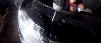
- Using a screwdriver, disconnect the dashboard trim behind which the power supply is installed in your car.
- Unscrew the screws securing the power supply to the car body.
- Pull out the device: it will hang on the wires.
- Take the new power supply unit and, one by one, disconnecting it from the old device, insert all the necessary wires into the connectors of the new power supply unit.
- Install the new power supply in place by tightening the fastening screws and closing the instrument panel trim.
Replacing fuses for Volkswagen Jetta. Photos, instructions on how to change fuses on a Jetta 6
Kia ceed 2021: Korean golf-class perfection
Replacing fuses in a 2012 Volkswagen Jetta is a very simple procedure. Any driver can change fuses with his own hands. The Jetta 6 is equipped with fuses of various ratings: 5, 10,15, 20, 25 and up to 80 amperes.
Where are the Jetta fuses located?
The fuses on the Jetta 6 are based in two places. The first is under the hood, on the right “driver’s” side, near the battery. The second is in the cabin, under the panel, in the area where the driver’s left knee is located.
To replace, you only need tongs, which can often be found in one of the blocks.
How to change Jetta fuses
First you need to remove the fuse box cover. Under the hood it is secured with a latch at the rear, and in the cabin it is simply removed using the lower edge. Next, you need to take pliers and pull out the required fuse, which a fuse diagram will help you find. Such a diagram is often drawn on the block cover, but unfortunately this is not the case with the Jetta; it has neither a layout diagram nor fuse ratings. Therefore, it should be found in the user manual or repair manual. If you do not have such a brochure, then the Jetta 6 fuse diagram is available in our photo report.
It is worth inspecting the fuse under the light to make sure that its thread has blown. Then eliminate the reason why it blew and install a new fuse of the same rating as its predecessor.
etlib.ru
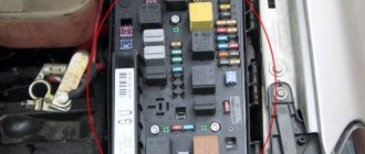
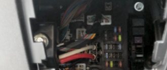
Fuse and relay box
It is located in the car interior under the instrument panel, on the driver's side under a protective cover.
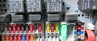
Photo - example
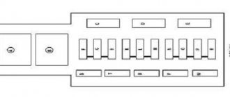
Option 1
Option 1 (models before 08.1987)
Scheme
Description of fuses
| 1 | 30A Electric fan |
| 2 | 10A Brake light |
| 3 | 10A Cigarette lighter, radio, clock, interior light |
| 4 | 15A Hazard alarm |
| 5 | 15A Fuel pump |
| 6 | 15A Fog lamp |
| 7 | 10A Rear left parking light |
| 8 | 10A Rear right side light |
| 9 | 10A High beam right headlight, high beam indicator lamp |
| 10 | 10A High beam left headlight |
| 11 | 15A Windshield wiper, windshield washer, headlight washer |
| 12 | 15A Windshield wiper and washer for the rear door glass, coolant level warning lamp, electric outside rear view mirror |
| 13 | 20A Heated rear window of the tailgate, heated outside rear view mirror |
| 14 | 20A Heater fan |
| 15 | 10A Reversing lamp, gear selection lamp (automatic transmission) |
| 16 | 15A High tone horn |
| 17 | 10A Automatic carburetor starter, electric intake pipe heater, forced idle fuel shut-off valve |
| 18 | 10A High and low tone horn, front seat heating, parking brake light |
| 19 | 10A Turn signal |
| 20 | 10A License plate light, glove box light, fog lights |
| 21 | 10A Low beam left headlight |
| 22 | 10A Low beam right headlight |
In this version, fuse number 3 at 10A is responsible for the cigarette lighter.
Relay designation
| I | Free |
| II | Intake pipe heater relay |
| Fuel pump relay | |
| Glow plug relay | |
| III | Seat belt warning relay |
| IV | Gear Selection Relay |
| V | Air conditioner relay |
| VI | Horn relay |
| VII | Fog light relay |
| VIII | Contact relief relay x |
| IX | Free |
| X | Washer relay |
| XI | Tailgate wiper and washer relay |
| XII | Alarm relay |
| XIII | Seat belt warning relay |
| XIV | Seat belt warning relay, heated rear window, pressure warning lamp |
| XV | Headlight washer relay |
| XVI | Idle speed increase relay |
| XVII | Fuse for rear fog lamp, air conditioner |
| XVIII | Fan relay |
| Coolant level alarm relay | |
| XIX | Power window fuse |
| XX | Driver seat heating relay |
| XXI | Passenger seat heating relay |
| XXII | Fuel cut-off relay for forced idle |
| XXIII | Free |
| XXIV | Free |
Option 2 (models from 08.1987)
Scheme
Purpose of fuses
| 1 | 10A Low beam left headlight |
| 2 | 10A Low beam right headlight |
| 3 | 10A Instrument lamp, license plate lamp |
| 4 | 15A Glove compartment lamp |
| 5 | 15A Windshield wiper and washer |
| 6 | 20A Heater fan |
| 7 | 10A Right rear light, parking light |
| 8 | 20A Heated rear window |
| 9 | 15A Fog lights |
| 10 | 10A High beam left headlight |
| 11 | 10A High beam right headlight |
| 12 | 10A Horn |
| 13 | 10A Reversing light, heated washer |
| 14 | 10A Fuel cut-off valve (diesel engine) |
| 15 | 15A Instrument panel |
| 16 | 10A Hazard Alarm |
| 17 | Free |
| 18 | 30A Electric fan, air conditioning relay |
| 19 | 10A Brake light |
| 20 | 15A Interior lighting |
| 21 | 10A Radio and cigarette lighter |
In this version, fuse number 21 is responsible for the cigarette lighter
Relay decoding
| I | Air conditioner relay |
| II | Tailgate wiper relay |
| III | Ignition system relay |
| IV | Contact relief relay x |
| V | Coolant level alarm relay |
| VI | Alarm relay |
| VII | Headlight washer relay |
| VIII | Windshield wiper switching relay |
| IX | Seat belt warning relay |
| X | Fog light relay |
| XI | High and Low Pitch Horn Relay |
| XII | Glow plug relay |
| XIII | Electric fan relay |
| XIV | Intake pipe heating relay |
| XV | ABS pump relay |
| XVI | ABS relay |
| XVII | Free |
| XVIII | Free |
| XIX | Automatic transmission relay |
| XX | Glow plug control relay |
| XXI | Power window relay |
| XXII | ABS fuse |
| XXIII | Air conditioner fuse |
| XXIV | Power window fuse |
General purpose relay
- 4 or 29 - seat belt warning relay
- 13 - air conditioning compressor
- 15 — PTF
- 18 — unloading of tire X
- 19 or 99 - windshield wipers (99 - with adjustable pause)
- 21 - hazard warning indicators
- 22 — trailer direction indicators
- 30, 32 — Injection and ignition system relay
- 31 - secondary air valve relay
- 32 - ECU power supply
- 33 — headlight washer
- 36 — buzzer (signalling lights off)
- 42 - engine overheat relay (also 43)
- 43 - indicator of drop in coolant level (up to 91)
- 46 — preheating time relay
- 53 - two-tone signal. (solid color - jumper)
- 54 — cessation of power supply to the pump. XX
- 55 - increase in forced fuel supply. XX
- 61 — heating vp. collector
- 67 or 80 - fuel pump
- 72 - rear wiper
- 83 - freewheel lock relay (only on Syncro model)
- 90 - fuel purge pump relay
- 167 — Fuel pump or pre-heater relay (diesel) The following can be installed in any order:
- 220 - after-run relay
- 13 — electromagnetic clutch of the air inlet damper drive
- 79 - ABS ECU
- 78 - ABS pump
- 59 — heated seats
Location and layout
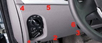
Let's look at the diagrams and location of the power supply in Volkswagen Golf cars of the second, third, fourth, fifth and sixth generations. In all cases, the device is located on the driver's side under the instrument panel. The only difference is that in models of the second and third generations the power supply is located on a shelf under the steering wheel. And in models of the fourth, fifth and sixth generations - directly in the dashboard on the side where the driver's door comes into contact with the panel.
Volkswagen Golf 2
The location of the block in this vehicle model is on the left side in the area of the driver’s seat under the dashboard. We invite you to familiarize yourself with the diagram and decoding of the power supply components.
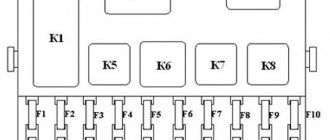
Fuse box FV Golf second generation
| Number | Purpose |
| 1, 2 | These power supply components are responsible for the functionality of the left and right low beam headlights. |
| 3 | This fuse ensures the operation of the instrument panel lighting and lamps that illuminate the license plate of the car. |
| 4 | This component ensures the functioning of the glove compartment lighting bulbs. |
| 5 | Responsible for the operation of the windshield wiper and washer motor. |
| 6 | Guarantees the operation of the interior heater fan. |
| 7 | Responsible for the operation of the right rear headlight and brake lights. |
| 8 | Provides heated rear window. |
| 9 | Fog lights. |
| 10,11 | Responsible for the performance of high beam lights. |
| 12 | Steering horn. |
| 13 | Provides functionality for rear position lights. |
| 14 | Determines the functionality of the fuel shut-off valve. |
| 15 | If this element fails, the operation of the instrument panel may be disrupted. |
| 16 | Guarantees the functionality of the alarm system. |
| 18 | If this element fails, the operation of the radiator fan and air conditioner is impossible. |
| 19 | Responsible for brake lights. |
| 20 | Car interior lighting. |
| 21 | Guarantees the operation of the multimedia system or radio, as well as the cigarette lighter. |
Fuses numbered 17 and 22 are spare.
Volkswagen Golf 3
The power supply circuit on this vehicle model is similar to the power supply installed in the second version of the car, but there are some differences. Therefore, we will consider the circuits and purpose of power supply elements separately. Location: on the dashboard on the left side, on the shelf under the steering wheel.
Diagram of the power supply installed in Volkswagen of the third version
| Number | Purpose |
| 1, 2 | Low beam lamps, left and right. |
| 3 | Car license plate lights. |
| 4,5 | Responsible for the operation of the windshield and rear window washer and wiper motors. |
| 6 | Guarantees the functionality of the heating element of the heating system. |
| 7,8 | If this component fails, the vehicle's rear and front side lamps will not work. |
| 9 | Rear window heating device. |
| 10 | Guarantees the functionality of the fog lights. |
| 11,12 | Responsible for the functionality of the left and right high beam lamps. |
| 13 | Steering horn. |
| 14 | If this component breaks down, the reversing lamps will stop working, as well as the washer nozzle heating device. |
| 15 | Responsible for the functionality of the gasoline shut-off valve, as well as the speedometer drive sensor. |
| 16 | If this element breaks down, malfunctions or inaccuracies in the operation of the instrument panel may occur. |
| 17 | Functioning of turn signal lamps and hazard warning lights. |
| 18 | If this fuse is blown, the car will not start because this component ensures the operation of the fuel pump. |
| 19 | Air conditioning and radiator cooling fan. |
| 20 | Lamp lights that turn on when you press the brake pedal. |
| 21 | Guarantees the functionality of car interior lighting bulbs, electronic clocks, and luggage compartment lighting. |
| 22 | Responsible for the operation of the multimedia system or car radio, as well as the cigarette lighter. |
Volkswagen Golf 4
Below is a diagram and purpose of power supply devices for the fourth version of PV. The block itself is located on the left side of the dashboard, near the driver's seat. To access it and see it in person, you need to remove the cover using a slotted screwdriver.
Power supply unit of the FV machine of the fourth version
Description and purpose of power supply components
Description and purpose of power supply components
Loading …
Volkswagen Golf 5, 6
For models of the fifth and sixth versions, the power supply circuit will be the same. The location of the power supply is on the left side of the instrument panel, in the area where the driver's door comes into contact with the dashboard. Below is a diagram and description of all components.
PSU for models 5 and 6
PSU for models 5 and 6
PSU for models 5 and 6
PSU for models 5 and 6
PSU for models 5 and 6
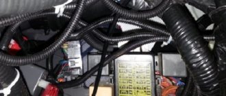
Changing the fuse diagram after
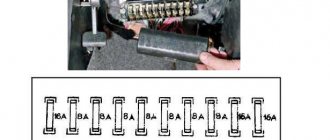
After 1988, fuses and relays were located as in the figure.
Decoding of PP values on a 2nd generation VolksWagen Golf.
| Electrical circuit or device | Denomination, A | Color | № |
| Electric motor of the engine cooling system fan | 30 | Green | 1 |
| Brake light bulb, tail light | 10 | Red | 2 |
| Car radio, cigarette lighter, clock in the instrument panel, interior lighting | 10 | Red | 3 |
| Emergency button | 15 | Blue | 4 |
| +12V fuel pump power supply | 15 | Blue | 5 |
| Front fog lights | 15 | Blue | 6 |
| Side light bulb, right side tail light | 10 | Red | 7 |
| Side light bulb, left side tail light | 10 | Red | 8 |
| Headlight high beam bulb, left side | 10 | Red | 9 |
| Headlight high beam bulb, right side | 10 | Red | 10 |
| Windshield wipers, headlight washer motor, windshield washer motor | 15 | Blue | 11 |
| Rear view window wiper, rear view window washer motor, electric exterior rear view mirror, engine coolant level indicator | 15 | Blue | 12 |
| Heated rearview glass, heated rearview mirror | 20 | Yellow | 13 |
| Interior heating fan drive | 20 | Yellow | 14 |
| Automatic transmission selector light, reverse gear light | 10 | Red | 15 |
| High pitch horn | 15 | Blue | 16 |
| Fuel supply interrupter for the internal combustion engine, heating of the intake manifold, PU of the carburetor internal combustion engine | 10 | Red | 17 |
| Low-pitched horn, heated front car seats, handbrake indicator | 10 | Red | 18 |
| Turn signal bulbs, front and rear | 10 | Red | 19 |
| Front fog lights, rear license plate light, glove compartment light | 10 | Red | 20 |
| Right low beam bulb in the headlight | 10 | Red | 21 |
| Left low beam bulb in headlight | 10 | Red | 22 |
| Relay connector description | Note | Designation on the diagram | |
| Reserve connector | I | ||
| Air heating in the intake manifold | Carburetor internal combustion engine | II | |
| Fuel pump | Single injection | ||
| Pre-heating plugs | Diesel internal combustion engine | ||
| Front seat belt buzzer | Diesel internal combustion engine | III | |
| Gear selector | Automatic transmission | IV | |
| Air conditioning compressor | V | ||
| Two-tone horn | VI | ||
| Front fog lights | VII | ||
| Power relief of terminal X | VIII | ||
| Reserve connector | IX | ||
| Headlight washer | X | ||
| Rear window wiper and washer motor | XI | ||
| Emergency crew | XII | ||
| Seat belt buzzer | XIII | ||
| Heated rear view glass, engine oil pressure indicator, seat belts | XIV | ||
| Windshield washer motor | XV | ||
| Adjusting idle speed | Single injection | XVI | |
| Reserve connector | Air conditioner | XVII | |
| Electric drive of the internal combustion engine cooling radiator fan | Carburetor internal combustion engine | XVIII | |
| Coolant level indicator in internal combustion engine | Diesel internal combustion engine | XVIII | |
| Reserve connector | Window lifters | XIX | |
| Heated driver's seat | XX | ||
| Heated front passenger car seat | XXI | ||
| Fuel supply switch | Carburetor | XXII | |
| Reserve connector | XXIII | ||
| Reserve connector | XXIV |
Video “Indicator fuse, demonstration of operation”
In this video you can clearly learn about the safety devices in the Volkswagen Jetta.
Almost the entire system of Volkswagen Jetta power circuits, on which the operation of the vehicle’s equipment depends, is protected by fusible contact elements, which are combined into a so-called fuse block. Through relays, which are also included in this block, such energy consumers are connected as:
- lighting lamps;
- electric cooling fan motors;
- fuel pump, etc.
This unit and its serviceability are of particular importance for the stable operation of the main systems of the Volkswagen Jetta model. That is why these contact elements are combined and placed in a special mounting block. According to the instructions, it is located in the interior of the Volkswagen Jetta, on the left side of the instrument panel. There is a top shelf, which in turn consists of:
- lower casing of the instrument panel;
- fixing screw;
- instrument panels;
- cover protecting the unit.
This is where the block is located, where in case of a malfunction you need to look. As a rule, a faulty or burnt-out contact element will give itself away. It will have a melted metal part with a black coating. It is also possible that the colored case will be distorted.
Additional fusible elements
In some versions of Volkswagen Golf 3rd generation vehicles, additional fuses may be used. The following additional elements are used in the interior fuse and relay module:
- rated 30A - power supply to the ABS system relay;
- rated 30A - power supply to the relay of the hydroelectric unit of the ABS system;
- rated 10A - air conditioning compressor for cars without climate control;
- rated 30A - interior ventilation motor with the ClimaTronic system;
- with a nominal value of 5A - controller of the ClimaTronic system;
- rated 5A - +12A power supply to the on-board network of a towed trailer.
For a diesel internal combustion engine, an additional PP for the engine warm-up system is used, with a rated current of 60 A. It is located separately, on the engine panel under the hood.