07/18/2021 25 143 GAS
Author: Ivan Baranov
Every car enthusiast knows that the ignition system in any car is needed to ignite the combustible mixture in the engine. GAZ trucks are no exception. In this article, we propose to find out what the ignition procedure for the GAZ-53 is, what malfunctions a car enthusiast may encounter, and how it is configured.
[Hide]
Design of the GAZ 53 ignition system
The GAZ-53 is equipped with a non-contact transistor ignition system, the primary circuit of which produces a voltage of 12 volts. The ignition system is considered battery-based, consisting of sources of electric current, which can be a battery, ignition coil, switch, sensor-distributor, and other electrical equipment gas 53, which most often causes problems, since it needs to be adjusted, spark plugs with tips, additional resistor, ignition switch, low and high voltage wires.
The drawing shows a complete diagram of the GAZ-53 ignition system
The ignition system is one of the most important systems in a car, since the operation of the engine, as well as the fuel consumption of the entire car, depends on its proper operation. To suppress radio interference created by high voltage wires and spark plug tips, distributed resistance is installed on the former, and suppression resistors are installed on the latter.
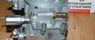
The ignition system contains a B 116 brand coil, the purpose of which is to convert low voltage current to high voltage.
In turn, the coil consists of a transformer in which an iron core is mounted. The primary winding is wound on top of this core, and the secondary winding is below it. The transformer itself is a steel case, which is hermetically sealed; oil is poured inside it along with the core.
To maintain this transformer, a plastic cover is provided that can withstand high voltage.
The first GAZ 53 trucks had a contact-transistor ignition system, then it became contactless electronic. Since the contact (or contact-transistor) system is already hopelessly outdated, we will consider a contactless system. The GAZ 53 ignition system consists of a low-voltage and high-voltage circuit. The low voltage circuit includes:
Checking the ignition coil with a multimeter
The secondary (high-voltage) circuit contains the following elements:
Source
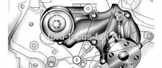
Installation of distributor drive
When installed, the actuator has a defined single position. If you look into the drive. You can see the groove on the end of the shaft. The groove is offset relative to the center of the shaft axis. If you are on the right side when the car is moving. Then the groove should be located exactly as shown in the figure. Moreover, the groove must be parallel to the engine axis
The drive engages the camshaft using helical gears. It is as if one gear is screwed into another. If you install a groove on the drive, it should already be installed on the engine. The shaft will rotate along the gear teeth. As a result, the shaft rotates and the drive occupies the wrong position.
Therefore, before installation, the drive shaft must be turned to the left by approximately one gear tooth.
When the helical gears engage, the shaft will snap into place
It may not work out the first time, but you need to achieve this exact position.
The task becomes even more complicated. What you need to do is get the flats of the hexagon into the cavity of the oil pump.
If everything is done correctly, and during installation the drive does not sit in place. The edges of the oil pump did not coincide with the edges of the drive shaft.
The situation can be corrected. It is necessary to rest the screwdriver against the drive. To allow the gears to mesh a little. Then you should turn the crankshaft. The drive will begin to rotate. And the oil pump will not move. The edges will align. And the drive will fall into place. After which the crankshaft must be turned back. In this case, it must be held from above. Otherwise the drive will come out. Helical gears will squeeze it out.
Align the marks on the flywheel or pulley again. Make sure that the distributor is positioned correctly. Now the drive mounting fork is installed. And it is pressed with a nut. There is also a gasket on the drive. It is advisable to lubricate it with sealant. Without a gasket, oil will leak from under the drive. Installation of the Gas 53 distributor drive is completed. It is necessary to install the distributor and set the ignition correctly.
Source
Design of the GAZ-53 ignition system
In order to repair and configure the SZ on the GAZ-53, you need to know how it works.
These trucks are equipped with a contactless protection system, which consists of the following components:
Knowing the structure of the protection system, the connection diagram of the protection device and its other components, as well as the functions that each element performs, you can identify problems based on their symptoms and eliminate their cause. All components of the system can be divided into groups according to the tasks performed.
For normal operation of the internal combustion engine, the following conditions must be met:
The entire electronic ignition system consists of two circuits: primary and secondary.
The primary includes the following elements:
The secondary circuit includes:
When the primary circuit receives power, a magnetic field is generated in the breaker. The rotation of the distributor interrupts the current in this place, which leads to the disappearance of the magnetic field. At this moment, a signal appears on the secondary winding, which goes to the cylinders.
Photo gallery
Successful sparking is ensured by stable operation of the motor and the appearance of sufficient voltage on the electrodes. The power of the spark is affected by the size of the gaps between the electrodes and the amount of incoming voltage.
With a weak spark or its absence, fuel consumption increases and engine power decreases.
How to set the piston of the first cylinder to TDC
Now you need to make sure. That the first cylinder is at TDC at the moment of compression. There are two ways you can do this.
But they close for a moment. When graduation closes. The intake will immediately begin to open. In the case when the valves are closed under compression when the piston approaches TDC and during its further movement, the valves remain motionless for some time.
After the position of the piston of the first cylinder is precisely determined. And the marks are strictly in their places. You can install a distributor drive.
Instructions for setting up the ignition
The cause of engine overheating and loss of power may be late ignition. This may manifest itself as popping noises in the intake manifold. Therefore, you need to know how to install the ignition correctly (the author of the video is Nail Poroshin).
Installation is carried out according to the marks as follows:
It is necessary to set the ignition timing of the GAZ-53 accurately, since with deviations the engine power decreases and fuel consumption increases. In addition, burnout of valves, pistons, breakdowns in the cylinder head gasket and other problems associated with detonation are possible.
Therefore, the final adjustment is performed with the engine running, which warms up to a coolant temperature in the range of 80 - 90 degrees. With the engine running at idle speed, you need to loosen the fasteners of the distributor with a 10mm wrench so that it can be turned. After slightly turning the distributor counterclockwise, tighten the fastening bolt.
Pressing on the gas is how the power unit works. If you hear a “ringing of fingers,” that is, detonation occurs, turn the distributor clockwise in the opposite direction. Through trial and error we set the desired advance angle.
The test is done on a moving vehicle. With stable operation of the power unit, tuning is no longer needed.
Sometimes the distributor is pushed to the extreme position, but the adjustment is not enough. In this case, you need to check the position of the distributor drive relative to the engine.
A check is performed with the engine not running:
Correct position of the distributor
In order to install the drive, you need to understand how the engine works. The distributor should be in this position. So that the spark generated by the ignition coil jumps to the spark plug of the first cylinder. At the moment of fuel compression. This is exactly the position of the distributor. Must match the position of the drive. During the working cycle the piston is fired twice. Suitable for TDC. The first time the fuel mixture is compressed. For subsequent ignition and expansion of burning fuel. The second time the piston squeezes out the exhaust gases. And when moving down, it sucks in a new portion of the fuel mixture.
Spare parts for trucks
Full model range: GAZ-3307, 53, GAZ-3309, GAZ-66, 3308, 33081, 33086, GAZ-33104
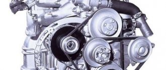
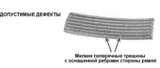
Timing belt of the GAZ-53 engine
The timing belt of the GAZ-53 engine consists of a camshaft, valves, rocker arms, and pushers.
The GAZ-53 camshaft is steel, forged. In addition to the cams, it has five bearing journals and a drive gear for the ignition distributor and oil pump.
GAZ-53 camshaft bearings are rolled bushings, which are made of steel strip filled with Babbitt alloy or aluminum alloy with tin.
The intake and exhaust cam profiles are not the same. The width of the cams is ground to a cone. The inclination of the cone generatrix and the spherical surface of the pusher impart a rotational movement to it during operation, reducing wear on the end, its cylindrical part and the pusher guide in the cylinder block.
The cams, bearing journals and drive gear of the ignition distributor and oil pump are surface hardened.
The GAZ-53 camshaft is driven by a pair of gears from the crankshaft. The axial movement of the camshaft is limited by a steel thrust flange 7.
The following are installed on the front journal of the GAZ-53 camshaft: spacer sleeve, thrust flange 7, camshaft drive gear 9, eccentric balancer 6, fuel pump drive eccentric 5. All parts on the front journal are secured with a special bolt and washer.
Fig.1. Valve drive mechanism GAZ-53
1—hole for oil outlet; 2— pushers; 3.7 - lower and upper ends of the rod, respectively; 4 — rod; 5— valve; 6 — valve guide; 8—yoke; 9 - lock nut; 10 — adjusting screw; 11 — rocker axis; 12 - cracker; 13 - plate; 14 - spring; 15 — support washer
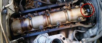
Valve clearances
The gaps are adjusted using a feeler gauge. On the intake valves the gap should be 0.3 mm and on the exhaust valves 0.4 mm. There is no point in catching hundredths of a millimeter. When tightening the adjusting bolt with a locknut, these hundredths will still be lost. It is enough for the feeler gauge to move between the valves and the rocker arm with little force when compressing the adjusting bolt. But it was not clamped. Such thermal clearances are used on almost all engines. To begin the adjustment, you need to unscrew the lock nut on the adjusting screws. You need to unscrew it a few turns. So that it does not interfere with reducing the gaps later. The feeler gauge is inserted between the valve and the rocker arm. The adjusting screw is tightened with a screwdriver. And it is brought to the optimal clamping of the probe. Then the locknut is tightened. The screw must be secured with a screwdriver. If it doesn't work out. Then you can insert the key 11 into the edges of the screw. And hold the screw with a wrench. And so on for each next cylinder in order.