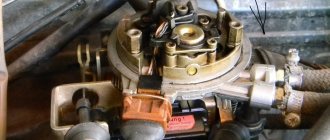
Distributor cover
Ensuring a stable and quick start of the vehicle is one of the well-known tasks of any owner of a used car. The starting system must always function in ideal condition, because it acts as a kind of starter during the operation of the vehicle. We will learn from the article how to check the ignition distributor cap, analyze the instructions, and watch a video review.
How to check the distributor The answer is here
Distributors are so-called ignition distributors. Used in ignition systems of carburetor internal combustion engines. Method 1
Instructions
1. To check the distributor, you need to place the car in the garage and close the doors. Turn on the engine and see if there are sparks.
2. When they are present, it means that in some place there has been a violation of the insulating layer. In daylight, the spark may not be visible.
3. The lid should not be damp and clean, because in some cases it may be burnt. By checking the connection of the wires, you can make sure that the contacts are intact or broken. As for the terminals in the cover, they should not be freely removed.
4. You should also check the rotor for burnout. It should be pumped. If there is no play, then there will be no gaps in the contacts.
Method 2
Instructions
To check the distributor, you should pay attention to the gaps and wear in the contacts. Approximate size - 1-3 mm
In the case where the contacts are burnt (flat), they need to be cleaned.
2. You can check the distributor by connecting a lamp to one of the side terminals of the distributor. Then turn on the ignition and crank the engine. In this case, the starting handle or pushing the machine (high gear) can help.
3. The lamp that lights up and goes out in this case should light up after an equal amount of time (four-cylinder engines - the lamp lights up and goes out every 0.5 revolutions). If this does not happen, it means that a short circuit occurs in some place, for example, the body touches the moving part of the contact.
4. If a capacitor is installed, if it malfunctions, a short circuit will also occur. When a person wants to check the distributor, if it is present and in working order, it can simply be turned off.
5. A quick way to check the distributor is to remove the wire from the spark plugs. Then you need to take the contact (5 mm gap), place it on the housing base and turn the motor. In this case, if the distributor is in good condition and normal operation, a spark will occur.
Distributor and its malfunctions
The distributor circuit assumes the presence of such elements as:
- low voltage current breaker;
- high voltage current distributor;
- centrifugal ignition timing regulator;
- vacuum ignition timing regulator.
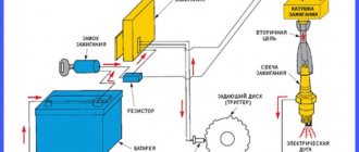
The distributor circuit is designed so that at a certain moment the breaker opens the primary ignition circuit, as a result of which a high voltage current is created in the secondary winding of the ignition coil. Through the distributor, this current is transmitted to the spark plugs in certain cylinders. The regulators automatically adjust the ignition timing, which depends on the current operating mode of the engine.
Distributor device
The distributor breaker is an electromechanical part and consists of the following parts:
- shaft;
- movable contact plate;
- movable contact plate;
- capacitor;
- frame.
The breaker shaft consists of two main parts. On one of them, depending on the type of breaker, cams are installed, the number equal to the number of cylinders in the engine. This distributor device is not very reliable, since a large number of contacts, as well as the presence of moving parts, lead to regular problems with this unit.
The distributor device, as well as its use in general, are outdated from the point of view of modern electrical equipment, but in our country there are still a lot of carburetor engines, so the problem of the performance of this unit is currently relevant.
As for where the distributor is located in the car, most often it can be found under the hood next to the engine, near the cylinder head or on it. Although the exact location of the node depends solely on the model of the machine.
The following signs indicate that the distributor is malfunctioning:
- When there is a spark on the central wire, but not on the spark plug wires, this indicates a breakdown of the slider.
- the car jerks periodically when driving;
- Unstable engine operation at idle;
- the engine does not start at all;
- the knocking of the piston fingers is heard while accelerating;
- the speed increase dynamics decreased;
- fuel consumption has increased.
In most cases, the causes of distributor failure are:
- Breakdown of the roof and ignition coil occurs due to large gaps in the contacts of the distributor cover and slider, spark plugs and bad candlesticks.
- burnout of the runner;
- oxidation or shorting of contacts under the cover;
- breakdown of the distributor cover;
- failure of one of the sensors;
- problems with the shaft bearing and other problems.
In each of these cases, replacement is required. But at the same time, for almost any car, it is possible to change not the entire distributor, but only its failed part, which is an advantage, since it significantly reduces the cost of repairs.
Often, problems in the operation of the contact distributor appear due to changes in the gaps in the contacts or their contamination, so it is necessary to check after 10 thousand km.
The most basic check of the distributor is a visual assessment of the condition of the slider, contacts and cover.
In a contactless distributor, the main malfunction is the failure of the hall sensor or inductive sensor.
To check the ignition system and distributor, among other things, observe the spark on the unscrewed spark plug after starting the engine. In garage conditions, you can also check using measuring instruments or indicators.
The distributor capacitor is also one of the parts that often fail. It helps to increase the voltage supplied to the spark plugs when the engine starts. And in order to check it, you need to disconnect it and touch the “ground”, and if a characteristic crackling sound is heard and a voltage drop is observed, the capacitor is working, if this does not happen to the replacement part.
A distributor is always a dismountable unit that can be disconnected, removed from the car, disassembled into components, a problem can be detected and eliminated by replacing the damaged part.
It is located in the ignition distributor, under the cover. Consists of 2 plates: central and spacer. Models may be different, but the design scheme of operation is the same.
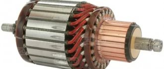
Rotor (runner) check
If the internal combustion engine spins poorly or does not start at all, and there is no spark at all 4 spark plugs, doubt immediately falls on the rotor (runner).
Checking the rotor is easy:
- The distributor cover should be pulled out.
- Bring the central armor wire from the coil to the runner (middle plate).
- If a spark forms between the wire tip and the plate, the rotor is 100% broken.
Finally, I would like to recommend it to all owners of cars equipped with an old ignition system. Change it to contactless as soon as possible. This way you will save your budget, time and nerves.
Tired of paying fines? There is an exit!
Forget about fines from cameras! An absolutely legal new product - Traffic Police Camera Jammer, hides your license plates from the cameras that are installed in all cities. More details at the link.
- Absolutely legal (Article 12.2);
- Hides from photo and video recording;
- Suitable for all cars;
- Works through the cigarette lighter connector;
- Does not cause interference to radios and cell phones.
Purpose of the mechanism
Before we tell you how a faulty distributor should be checked to identify breakdowns, let’s look at the purpose of the device. The breaker is a unit designed to detect the moment of formation of high-voltage signals in the system. The distributor is installed on both carburetors and injectors, and this mechanism is used to distribute electric ignition among the engine cylinders.
In its design, this mechanism differs from others in the presence of various elements in the structure, which tend to wear out over time. When the first signs of malfunctions in the operation of the distributor are identified, the device must be removed and repaired, since its condition largely determines the operation of the power unit and its characteristics.
In addition to setting the ignition, the distributor performs the following functions:
- interrupts the primary ignition circuit, which ensures the appearance of a high-voltage pulse;
- distributes the spark among the cylinder spark plugs in a certain sequence.
Breaker device design
Signs of a faulty distributor cap
Distributor
is an ignition distributor, a mechanism designed to create high-voltage pulses in the ignition system in order to distribute ignition among the cylinders. In other words, the task of the distributor is to supply a spark in the selected sequence to the spark plugs of different cylinders synchronously with the operation of the camshaft.
These devices are used in gasoline carburetor engines. Diesel engines do not have an ignition system, and injection systems do not use a breaker.
Distributor repair
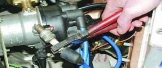
When problems have been identified in the operation of the distributor, it is necessary to begin preparing to repair the element. And the first thing that needs to be done in this case is to properly dismantle the distributor. To do this, first you need to check if there are any sparks on the running power unit. If there are sparks, then this indicates an insulation failure.
After performing this check, you need to remove the negative wire from the battery terminal. Disconnect the high-voltage wires and the vacuum hose from the distributor itself. Remove the cable from the throttle valve drive and remove the bracket. Apply marks to the distributor cover and auxiliary device drives to maintain the starting ignition timing.
Using a screwdriver, press the connector lock and pull out the wires. Then pull out the rubber plug and rotate the crankshaft so that the piston of the first cylinder is at the dead center. Make sure the flywheel marks match the middle division on the housing scale. At the last stage, the car owner must unscrew the nuts along with the element cover and remove the element itself. Installation of the device must be done in the same way. but in reverse order.
The main reason for checking the ignition distributor, the engine electrical system, is to check for damage that is not subject to normal repair. Typically, the ignition distributor is checked on a test bench. Before installing the distributor on the test bench, make sure that the condition of the breaker contacts is normal.
Contacts that are dirty, burnt or have signs of erosion will need to be treated. For processing, use a velvet file; the use of abrasive materials or sandpaper is prohibited. After cleaning, clean the contacts well.
Wipe the ignition distributor cover from dust and oil residues
When installing the ignition distributor on a control test bench to check the ignition devices, connect it to an electric motor that can adjust the rotation speed.
The control test bench must be able to connect the distributor with the ignition coil and battery, similar to the ignition system diagram.
Connect the terminals of the distributor cover to spark gaps, the interelectrode gap of which is adjustable.
Set the interelectrode gap of the spark gaps to 5 mm, turn on the electric motor, set the rotation speed to 2000 rpm. Then increase the interelectrode gap to 10mm, and check for internal discharges in the distributor. The manifestation of internal discharges can be determined by a characteristic sound, or by an interruption and weakening of sparking at the stand's spark gap.
A serviceable distributor should not make noise at any roller rotation speed
To determine the characteristics of the centrifugal ignition timing regulator, set the interelectrode gap of the bench spark gap to 7 mm. At the stand, turn on the electric motor, the speed should be 150 - 200 rpm.
Mark the value in degrees on the graduated disk of the stand, gradually increase the rotation speed by 200 - 300 revolutions, use the disk of the stand to determine the number of degrees of ignition timing, it should correspond to that shown in the image.
- A - ignition distributor P125.
- B – ignition distributor 30.3706.
- Where is the vertical line? A corresponds to the ignition timing in degrees.
- And the horizontal straight line n is the rotation frequency of the ignition distributor shaft in minutes.
If the characteristic shown in the figure differs from the test indicators, it can be corrected and brought back to normal by bending the springs of the centrifugal regulator weights.
If you need to bring the indicator up to 1100 rpm, bend the thin spring strut, and if above 1100 rpm. min. then bend the thick spring strut. To increase the angle, reduce the spring tension; to decrease it, increase it.
To obtain the performance characteristics of the vacuum ignition timing regulator, set the rotation speed for the roller to 1000 rpm. On a graduated disk, determine the value in degrees at which one of the four sparks occurs and mark it. Next, slowly, as they say smoothly, increase the vacuum and record the number of degrees every 20 mm of mercury, record the number of degrees of ignition timing. Compare the obtained indicators with the values shown in the images.
Where the vertical straight line A is the ignition timing in degrees. And the horizontal straight line P is the vacuum in millimeters of mercury.
Between the various terminals and ground, check the insulation resistance using a megger.
To measure the resistance between ground and the low-voltage terminal of the breaker, it must be done with the breaker contacts open. At 25-30 degrees Celsius, the insulation resistance should be at least 10 MΩ (megohm).
If you measure the capacitance of a capacitor in the frequency range 50 - 1000 Hz, the capacitance should correspond to 0.20 -0.25 µF (microfarads)
Repairing a distributor is a rather complicated procedure, requiring the repairman to know the structure of the unit and the electronics in general. The complexity of the distributor design, the difficult connection diagram and the lack of electrician training among motorists reduce the possibility of its own repair to almost zero. It is based on this that garage technicians often prefer to completely replace a faulty distributor.
Often this approach is completely justified, as it significantly saves motorists’ time. However, when deciding to replace the distributor, you need:
- firstly, try to diagnose the exact malfunction of the device (for example, incorrect operation of high-voltage wires does not require a complete replacement of the distributor, because it is much easier and cheaper to simply change the wiring);
- secondly, consult with a specialist in the field of repairing ignition systems and make sure that it will be cheaper to replace the distributor rather than have it repaired by an electrician.
Let's say the need to install a new distributor is confirmed. In such a situation, it is quite advisable to save some money and carry out the replacement yourself. To organize the repair you will need:
- set of wrenches;
- spark plug key;
- screwdriver;
- rags;
- new distributor.
First of all, you need to unscrew the spark plug of the first cylinder and determine where the distributor is located specifically on your model; Next, we proceed to align the motor shafts in the desired position. To do this: jack up the front wheel on the right; close the spark plug hole with your finger; turn the wheel until air begins to press on your finger; Next, we gain access to the timing belt, remove the crankshaft flywheel plug and align the marks of the shaft pulley and the engine block.
We remove the distributor
This is where it is extremely important to remember the connection diagram for high-voltage wires. It's best to take a couple of photos of the attached distributor and mark each attached spark plug wire accordingly for identification.
the distributor is installed in the vehicle structure in the same way as the old unit; the gaps of the mechanical slider located under the distributor cover are set (if required, how to adjust the distributor - we’ll talk below); spark plug wires are mounted to it; low voltage wire is connected; the ignition timing is adjusted (again, if required).
In general, there are no particular difficulties in installing a new distributor. It is much more difficult to understand how to check the distributor for a particular malfunction, because this requires much more knowledge than is required to implement the process described above.
Before checking the cover or other structural elements, you need to prepare for repair work. Repairing the cover, replacing the distributor oil seal and other tasks to restore functionality are carried out after setting the marks. How to set marks - marks are applied to the device body, its cover, as well as the drives of auxiliary elements - this will allow you to maintain the required ignition timing without adjustment.
As for the repair itself, it is performed like this:
- After dismantling the device, the cover is diagnosed. If you notice that it is broken, then it will have to be replaced with a functional one.
- Next, you need to check the distributor slider - it needs to be changed if the fuse has melted or rust and fumes have appeared on the element.
- After these steps, the dust shield is dismantled - first, the voltage terminal is removed, after which the two bolts securing the Hall sensor support plate are unscrewed, and the plate itself is also removed after these steps. Having done this, remove the retaining ring from the plate pin, unscrew the bolts securing the vacuum corrector, and remove the component itself. Then the support plastic is pulled out and its bushing is diagnosed - there should be no signs of damage on it.
- Next, remove the spring ring that secures the coupling pin. If you see that the condition of the ring is sad, it needs to be changed, because otherwise it will be of no use. Next, you need to knock out the pin from the coupling - it can only be replaced if the pins have worn out.
- Many car owners are interested in the question of how to check the capacitor. This element can also fail, so check the capacitor first. You will need to prepare a multimeter. Diagnostics is carried out by a tester.
- A centrifugal control device with a roller is removed from the structure. The distributor is replaced if there are gaps, signs of wear and other damage (the author of the video is Roman Romanov).
Capacitor
Distributor capacitor
It is customary to always talk about two methods for checking a distributor capacitor. The first method is to measure the capacitance of the capacitor, since when it drops, the ignition system begins to malfunction, up to the complete stop of the internal combustion engine. You can easily diagnose the capacitance of a capacitor using a multimeter with the appropriate capacitance testing function.
It is not necessary to remove the capacitor to check. It will be possible to unscrew only its central contact.
Check algorithm:
- The device is set to mode up to 20 microforat.
- The multimeter probes are connected to the capacitor body and its main terminal.
0.20-0.25 uF is a normal value for VAZ car models. 0.17-0.25 μF – Gas, Moskvich, Zaporozhets and other OA models. If the device readings do not match the factory data, then the capacitor is faulty.
The second way to check the capacitor is to use a homemade device with a tested and working capacitor.
Here's what's done:
- The capacitor being tested on the machine is disconnected from the main contact and taken to the side.
- One of the probes and clamps of the homemade device is connected to the released contact. Another probe goes to ground (any convenient place in the distributor body).
- The internal combustion engine starts.
- If its operation is stabilized, it functions normally at all speeds, there are no dips, etc., then doubts about the malfunction of the capacitor that was there are 100% justified.
In addition, with a working capacitor, the spark between the contacts of the distributor strikes noticeably, it is clearly visible if the distributor needs to be disassembled (remove the top). And most importantly, the discharge of the coil is felt and characteristic clicks sound. Conversely, if the capacitor is faulty, the coil will not discharge.
Possible breaker failures and their symptoms
How to check the ignition coil Repair of the distributor in the automotive industry is not carried out so often, which is due to the good reliability of this unit. Of course, there is no escape from breakdowns, but few people suffer from them. It is not so difficult to identify that it was the distributor that began to “pierce” the electric charge or grabbed another “sore”. The symptoms of malfunctions of the distributor-interrupter are specific and manifest themselves in the incorrect organization of the main functions of the device.
More precisely, possible replacement or adjustment of the distributor may be necessary if the following symptoms occur:
- the spark is gone;
- the ignition operation is upset;
- the battery stopped charging while the machine was running (not on all models);
- the car began to jerk while driving;
- Unburnt gasoline drips from the exhaust pipe.
As for specific faults, they are often represented by the following list:
- The distributor drive (rotor) has worn out or burned out. The malfunction is diagnosed through a detailed examination of the rotor and experimental verification of its correct operation. If an element breaks, it may be necessary to either install a new drive or completely replace the distributor;
- The network has broken through. This, by the way, can happen in any component of the distributor. Most often, the high-voltage wires that extend to the spark plugs from the distributor cover are affected. Other elements of the system (small wires, connectors of distributor parts, contacts, etc.) break down noticeably less often. Checking for this malfunction is carried out using a regular “ring”;
- The seals are worn out. Perhaps this is a rather rare breakdown with characteristic symptoms. To be more precise, we are talking about a general disorder of the ignition and untimely formation of a spark. For repairs, it is necessary to replace the distributor seals, and it is worth replacing not only faulty elements, but also those that work correctly, so to speak, for prevention;
- The distributor slider or the sensor responsible for distributing the charge between the spark plugs has broken. Characteristic signs of this breakdown are the inability to correctly configure the distributor or its complete failure to operate. The malfunction is eliminated by replacing the slider or sensor;
- The ignition coil has failed. This failure is characterized by either absent or incorrect sparking. Repair is carried out by replacing the burnt coil with a new one.
Other distributor malfunctions appear much less frequently. In any case, repairing this unit is not an easy task, so no motorist will be able to figure it out right away
To understand the whole essence of repairing a distributor, it is important to fully understand the principle of its operation and constantly practice. If you don’t want to learn all the basics of repair work, it’s better to entrust the repair to a professional who specializes in repairing car ignition systems
Detailed instructions, as well as practical recommendations regarding setting the ignition breaker, are given in the video below (author - Andrey Gorinov channel).
Design and characteristics of a slider with a resistor
The slider is replaced if this element can no longer perform its functions. You may need a multimeter for diagnosis.
How to check the slider at home, several options:
- The multimeter probes must be installed in the place where the slider itself is connected to the coal at the point of breakdown. To identify a breakdown, you need to carefully look at the device - the spark will go either completely to the side, or only partially. But it should be borne in mind that a breakdown cannot always be determined.
- Another diagnostic option is to test the device using a central cable type. You will only need to dismantle the cover itself, then bring the high-voltage cable from the reel to the distributor, then try to start the engine. When cranking the starter, if the distributor is broken, the spark will start to jump. If there is no slippage, then you don’t need to look for the cause of the problem here.
- If there is a crack on the runner, the spark will go to the side. In the event that the resistance of the element is completely burned out, but an attempt to restore the conductor could occur. In turn, this could lead to electrical breakdown of the element and its complete failure. In this case, it must be completely replaced.
After the repair, the distributor is adjusted. The adjusted mechanism is put in place; during installation, it is important to correctly match the marks and connect the high-voltage cables. The procedure for adjusting the ignition as a whole may differ depending on the vehicle, and there may be several adjustment options.
Loading …
The slider (rotor) with a resistor consists of several parts: a cast body, two rigidly fixed contacts (central, resting on a corner in the distributor cover, and a side one) and a cylindrical resistor located in a special recess. The housing is made of electrically insulating material; the contacts are usually fixed to it using rivets.
According to the method of installing the resistor, there are two types of sliders:
- With replaceable resistor;
- With a non-replaceable resistor - the part is filled in a recess with a special insulating compound based on epoxy resin or glassy materials.
The runners use powerful resistors of a special design with end leads, designed for installation between spring contacts. In domestic cars, resistors with a resistance of 5.6 kOhm are most often used, but in various sliders you can find resistors with a resistance of 5 to 12 kOhm.
VKZ
Vacuum or ignition regulator. It serves to select a more correct sparking moment. It has become an important link in the distribution system, because the rate of fuel combustion is not constant and can vary depending on pressure, temperature and other factors. Vacuum corrects these very shortcomings.
It is a diaphragm with a spring and a rod connected to a rotating platform with contacts. The diaphragm is driven by vacuum (air discharge).
The vacuum is secured to the distributor with just 2 bolts. A faulty regulator is a torn or clogged diaphragm. You can see it only after you manage to halve the VKZ. You just need to be sure that it is he who is faulty.
Note. Today you can find various VKZ models on sale. There are correctors for domestic models, even for classics. There is no significant difference between the models, but the clamps may not be suitable.
Of course, the membrane is also sold separately. If the membrane in a faulty VSC is faulty, then it will be enough to replace only it. Naturally, it should fit in diameter.
Article on the topic: Find out which flywheel is on the car
If everything was done correctly, the machine will immediately let you know about it. Acceleration from any gear will be much improved.
Procedure for adjusting the gap
How to test a resistor for functionality with a multimeter
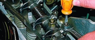
Remove the distributor cap and the slider and, slowly turning the engine crankshaft with the starting handle, set cam 4 to the position where the gap between the breaker contacts is greatest, i.e., when the breaker lever pad is installed on the top of the cam face. After this, use a flat feeler gauge to check the gap between the contacts.
If the gap does not correspond to the value indicated above, it is necessary to loosen the locking screw and, by turning the eccentric 23, set the required gap; then tighten the screw and check the gap again. Then you need to put the cover in place and secure it with latches 10. After adjusting the gap between the breaker contacts, the correct setting of the ignition timing is disrupted. Therefore, the ignition installation must be checked and, if necessary, clarified.
Electronic ignition device VAZ 2106
How to check the spark on a spark plug
In order to independently get a complete picture of the serviceability of an element of the ignition system, you need to figure out how to check the ignition coil with a multimeter. This procedure should not cause any particular difficulties.
First, the primary winding is checked, to the positive and negative contacts of which the device is connected in resistance measurement mode. Standard factory readings from different manufacturers may vary slightly, but average resistance values should be in the range of 0.4 to 2.0 ohms. If the device shows zero resistance, it means there is a short circuit in the coil, if infinity, you need to look for an open circuit.
Checking the ignition coil using a tester
To check the secondary winding, a multimeter is connected to the positive terminal of the coil and the terminal from the high voltage wire. The resistance value of this winding for coils with a plate core is 6-8 kOhm, for other types the parameter can exceed 15 kOhm.
It is possible to draw a conclusion about whether the obtained indicators are within the limits established for a particular model only by having an idea of its other technical characteristics: the duration and energy of the spark discharge, the spark discharge current and the inductance value of the primary winding.
Any malfunction of the ignition coil has a bad effect on the efficiency of the car engine, and this can lead to a decrease in its durability. That is why its timely diagnosis and repair (or replacement), if necessary, is necessary.
Checking the ignition coil using the “old-fashioned” method can damage the electrics of a modern car
To properly check this car part yourself, it is recommended to perform certain steps step by step. First of all, after removing the coil, you need to visually inspect it and make sure that there are no external signs of a short circuit: black dots indicating burnout, cracks, or other signs of breakdown.
In our country, for a long time, there were two equally popular ways to check the ignition coil for functionality: by checking the spark between the car body and the spark plug, or by measuring the resistance of the windings with a multimeter (tester). The use of the first method can be fatal not only for the coil, but also for the electronics of most modern cars, so its use is categorically not recommended by manufacturers. It is safer to check this component of the car with a measuring device.
You can adjust the ignition timing using a strobe, but the “manual” method has exactly the same effect. The only negative is that it takes longer to set up, but you can find the most effective ignition timing when the engine produces maximum power.
Installing the ignition on a VAZ engine photo
“Strobe” (as it is popularly called) is a device that pulses the crankshaft position mark at the moment of spark formation. To put it simply, while the engine is running, you can direct the beam of this device to a mark that serves to regulate the ignition timing. We see this mark as stationary, although it is located on a pulley or rotating flywheel (depending on the car model).
- We warm up the engine and remove the “choke”; the idle speed should be adjusted to normal (or slightly lower). We remove the vacuum tube that goes from the carburetor to the “vacuum manifold” of the distributor. Next, in this mode, we adjust and check the setting of the initial ignition timing. In the “classic”, this angle should be from 2 to 7 degrees, it depends on the engine displacement. For example, VAZ 2108-2110 - 1100 cm - 6 g, 1300 cm - 1 g, 1500 cm - 4 g. It is better to find out more in the car description).
- As the engine speed increases, to approximately 2000, the advance angle should increase by 5-7 degrees. If there are no changes, this means that the centrifugal regulator is not working. The main cause of failure may be jamming of the centrifugal mechanism, most often this occurs due to oxidation. For repairs, you need to disassemble, clean and lubricate. In addition, the springs of the mechanism often break.
- To check the operation of the vacuum ignition timing regulator, you need to make more effort, since its performance is related to the operation of the carburetor. The most important condition for good operation of the vacuum corrector is that while the engine is running at idle speed, there should be no vacuum in the tube that goes from the carburetor to the “vacuum manifold”. It should only appear when the engine speed increases. The moment a vacuum appears in the tube can be checked by carefully placing the tip of your tongue on it. You need to apply it to the end of the tube that we removed initially. If the carburetor does not provide timely vacuum in the tube, then the vacuum corrector will not work normally, even if the distributor mechanism is fully operational.
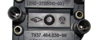
The contactless system (abbreviated as BSZ) of the Zhiguli includes six devices and parts:
- the main distributor of ignition pulses is a distributor;
- a coil that produces high voltage for a spark;
- switch;
- connecting cable with connectors;
- high voltage cables with reinforced insulation;
- spark plug.
The secondary winding of the coil acts as a source of high voltage pulses directed to the spark plugs
The coil operating as part of a contactless circuit differs in the number of turns of the primary and secondary windings. Simply put, it is more powerful than the old version, since it is designed to create pulses of 22-24 thousand volts. The predecessor supplied a maximum of 18 kV to the spark plug electrodes.
Trying to save money on installing an electronic ignition, one of my friends replaced the distributor, but connected the switch to the old “six” coil. The experiment ended in failure - the windings burned out. As a result, I still had to buy a new type of coil.
The cable with connectors is used for reliable connection of the terminals of the ignition distributor and the switch. The structure of these two elements should be considered separately.
To accurately connect the BSZ elements, a ready-made wiring harness with blocks is used
The following parts are located inside the distributor housing:
- a shaft with a platform and a runner at the end;
- support plate rotating on a bearing;
- Hall magnetic sensor;
- A metal screen with gaps is fixed on the shaft, rotating inside the sensor gap.
The contactless distributor still has a vacuum corrector connected by a vacuum tube to the carburetor
A vacuum ignition timing unit is installed externally on the side wall, connected to the support platform by means of a rod. A cover is attached to the top with latches, where the cables from the spark plugs are connected.
The main difference between this distributor is the absence of a mechanical contact group. The role of the breaker here is played by an electromagnetic Hall sensor, which reacts to the passage through the gap of the metal screen.
When the plate blocks the magnetic field between the two elements, the device is inactive, but as soon as a gap opens in the gap, the sensor generates a direct current. How the distributor works as part of an electronic ignition, read below.
The Hall sensor consists of two elements, between which an iron screen with slots rotates
The element is a control board protected by a plastic cover and attached to an aluminum cooling radiator. The latter has 2 holes for mounting the part to the car body. On a VAZ 2106, the switch is located inside the engine compartment on the right side member (in the direction of travel of the car), next to the coolant expansion tank.
The switch is placed on the left side member of the “six” not far from the expansion tank, the coil is located below
The main functional parts of the electronic circuit are a powerful transistor and a controller. The first one solves 2 problems: it amplifies the signal coming from the distributor and controls the operation of the primary winding of the coil. The microcircuit performs the following functions:
- gives commands to the transistor to break the coil circuit;
- creates a reference voltage in the electromagnetic sensor circuit;
- counts engine speed;
- protects the circuit from high-voltage pulses (over 24 V);
- adjusts the ignition timing.
The switch electronics are attached to an aluminum heatsink to cool the operating transistor
Cover and signs of its malfunction
Separately, there are symptoms that clearly indicate problems with the lid. Experienced motorists immediately distinguish them.
- “Trippling” of the power plant while the vehicle is moving, especially in damp, rainy weather.
- The speed does not increase while driving.
- An increase in the symptoms described above after driving a car through puddles.
Article on the topic: How to remove the starter lock with an alarm easily and simply
In any case, self-repair and adjustment of automotive components is much better than completely overhauling the car or replacing expensive spare parts. It is advisable to inspect the distributor cover yourself under good lighting.
Traces of punctures, plaque, mediocre condition of the coating, the presence of moisture or condensation inside the distributor - all this may indicate a malfunction of the cover.
Cover malfunctions
The microcracks themselves may not be visible at first, but their presence is already enough for the car to not function correctly.
Eliminating defects is a responsible process. In the case of the distributor cap, you can occasionally coat the surface with silicone-based sealant or remove deposits from the contacts. But if the malfunction is more complex, only a complete replacement of the cover will help.
Replacing the cover
Replacing it is not a painstaking operation, but it is worth showing careful attention. It is worth remembering that sometimes the nuances make all the difference for a beginner who decides to do auto repair on his own. For example, if the armor wires are incorrectly connected to the cylinders, the latter simply will not work.
The sequence of connecting the armored wires is, as usual, marked on the internal combustion engine itself or can be found in the car’s operating book. All the same, whatever one may say, it is easier to make marks on the elements themselves during the process of replacing them. The masters themselves recommend doing this.
As a rule, the documentation of some car models indicates the location of only one armored wire going to the 1st cylinder. The remaining wires are installed by the car owner himself against the rotation of the emergency.
The entire operation takes no more than 30 minutes. The price of a new cover ranges from 5 thousand rubles, which is quite inexpensive. After the cover is replaced, it will not be superfluous to treat all armored wires and the surface of the cover with a special composition, which significantly minimizes the likelihood of moisture getting inside.
During the process of updating the cover or slider, removal of the distributor will not be necessary. The cover is dismantled after disconnecting all armor wires.
ECU diagnostics is a job that cannot be delayed
The electronic engine control unit is rightfully considered one of the most important parts of a car. It is not for nothing that this device is called the “brains” of the car, because it is entirely responsible for the stable operation of almost all vehicle systems.
Every year more and more cars appear on the world market, the reliability and durability of which directly depends on electronic systems. Absolutely all manufacturers are trying to equip cars with the latest ECU models. At the same time, there are fewer and fewer mechanical components in cars.
Be that as it may, the use of electronics in the automotive industry is completely justified. Manufacturers of engine control units pay a lot of attention to the quality of materials and assembly of their products. That is why the “brains” of a car rarely fail. But, as they say, nothing lasts forever. And even a high-quality ECU will sooner or later fail.
We recommend that you read
- Repair of electronic engine control units
- Engine ECU programming
- Immobilizer bypass module - improving the car security system
- Auto scanner for self-diagnosis of any car
A wide circle of specialists has long compiled a list of the most common reasons why the ECU breaks down. These include:
- mechanical damage. The engine control unit is damaged by shocks and strong vibrations, which contribute to the appearance of microcracks in its circuits and housing;
- sudden temperature changes, as a result of which the engine control unit itself overheats;
- corrosion;
- depressurization and moisture ingress into the ECU housing;
- interference in the work of a block of people who do not have the necessary skills;
- the so-called “lighting up” from a car with the engine running;
- rearranging the terminals when connecting the battery;
- turning on the starter without a connected power bus.
- Do it! evokes uncontrollable desire in a woman in 15 minutes! Any one will be yours - just make her coffee! The whole truth about the stimulant reviews.
All of the above factors have different effects on the performance of the engine control unit. Some of them cause minor damage to the “brains” of the car, while others can instantly break the unit. Fortunately, there is still a way to prevent the complete breakdown of the unit - ECU diagnostics, which should be performed at least once a year. This is the only way to save on expensive repairs of a part or its complete replacement.
Many drivers believe that only professionals should check the operation of the engine control unit. In fact, almost every “brain” is equipped at the factory with a built-in self-diagnosis system. With its help, it will not be difficult even for an inexperienced driver to identify any faults with your own hands.
The engine control unit is a mini-computer that must perform specialized tasks in real time. The latter can be divided into 3 categories:
- processing of signals coming from sensors;
- calculation of impacts for controlling vehicle systems;
- adjusting the operation of actuators.
To start checking the status of the engine control unit, we will need to connect to it. This can be done using a special tester or laptop. On the latter, a program designed to read diagnostic data must be installed in advance. Modern cars are equipped with various ECU models.
We will carry out our own diagnostics using the free KWP-D program. In addition to the utility, we will need an adapter that supports the KWP2000 protocol. We begin diagnostics by connecting the adapter. We insert one end of it into the ECU port, and the other into the laptop. After this, turn on the car’s ignition and launch the program.
It is necessary to pay attention to the DTC section, which contains all errors generated by the engine. If there are any, then go to the “Codes” section, where we will see a breakdown of all existing failures. If you find no errors, then the engine is in perfect condition.
You should not ignore other sections of the table. The information they contain is no less important. Thus, the UACC parameter is responsible for the state of the battery. Normal values for this section are in the range of 14–14.5 V. If your battery voltage is less, you should carefully check the electrical circuits. Another important parameter is THR, which is responsible for the throttle position. During normal idling, the throttle position sensor will read 0%. Otherwise, you should contact a specialist.
Causes of coil failure
Partial damage to the ignition coil leads to unstable engine operation, and its complete breakdown makes it impossible to start the engine. That is why, when the engine stalls, loses power, or other signs of unclear operation, one of the first actions should be to check the ignition coil. This element fails quite rarely, and the malfunction, as a rule, is as follows:
- Insulation damage due to extreme heat, vibration or high voltage, which in turn leads to a short circuit in the coil windings;
- Overload caused by faulty high-voltage wires or spark plugs can cause the winding in the coil to break.
Distributor design
The distributor circuit assumes the presence of such elements as:
- low voltage current breaker;
- high voltage current distributor;
- centrifugal ignition timing regulator;
- vacuum ignition timing regulator.
The distributor circuit is designed so that at a certain moment the breaker opens the primary ignition circuit, as a result of which a high voltage current is created in the secondary winding of the ignition coil. Through the distributor, this current is transmitted to the spark plugs in certain cylinders. The regulators automatically adjust the ignition timing, which depends on the current operating mode of the engine.
The distributor breaker is an electromechanical part and consists of the following parts:
- shaft;
- movable contact plate;
- movable contact plate;
- capacitor;
- frame.
The breaker shaft consists of two main parts. On one of them, depending on the type of breaker, cams are installed, the number equal to the number of cylinders in the engine. This distributor device is not very reliable, since a large number of contacts, as well as the presence of moving parts, lead to regular problems with this unit.
The distributor device, as well as its use in general, are outdated from the point of view of modern electrical equipment, but in our country there are still a lot of carburetor engines, so the problem of the performance of this unit is currently relevant.
As for where the distributor is located in the car, most often it can be found under the hood next to the engine, near the cylinder head or on it. Although the exact location of the node depends solely on the model of the machine.
Malfunction of the contactless distributor.
When operating contactless distributors, the main malfunction is a malfunction of the hall sensor or inductive sensor. Minor wear and play in the bushings and bearing of the movable contact plate do not affect the operation of the distributor until the sensor rotor touches the stator.
Such malfunctions as breakdown of the slider, burning of its resistance. It can also break through the distributor cap between the cylinders. This malfunction is typical for non-contact distributors, since the secondary voltage in these systems is twice as high as in a contact one.
Signs of a Hall sensor malfunction
Hall sensor malfunctions manifest themselves in different ways. Even an experienced technician will not always immediately identify the cause of engine problems.
Here are some of the most common symptoms:
- The engine starts poorly or does not start at all.
- At idle, the engine runs rough and jerky.
- The car may jerk when driving at high speeds.
- The power unit stalls while driving.
If one of these signs appears, you must first check the serviceability of the Hall sensor.
Also, do not exclude other malfunctions of the ignition system found in cars.